
Related Manuals for Morgana Digifold Pro CB


Summary of Contents for Morgana Digifold Pro CB
- Page 1 Digifold Pro (CB/UL) DOCUMENT CREASING / FOLDING MACHINE SERVICE MANUAL Morgana Systems Limited United Kingdom Telephone: ( 01908 ) 608888 Facsimile: ( 01908 ) 692399 Website: www.morgana.co.uk APRIL 2012 ISSUE 2 174-037...
-
Page 2: Introduction
MORGANA DIGIFOLD Pro i ..Introduction The purpose of this manual is to explain the procedure for dis- mantling and re-assembly of the major assemblies on the Morgana Digifold machine. All the engineering adjustments are shown at the end of each relevant section. -
Page 3: Identification
Digifold Pro Pan head and Cross-head countersunk screws all have metric Taptite threads and Pozi-drive recesses. Use No.2 point Pozidriv or Supadriv drivers for all screws M4 & above, and No.1 point drivers for M3 & below. WARNING WORK SHOULD BE CARRIED OUT BY A TRAINED AND COMPETENT ENGINEER AND ALL SAFETY PROCEDURES SHOULD BE ADHERED SWITCH OFF MAINS POWER BEFORE COMMENCING. -
Page 4: Table Of Contents
INDEX Introduction ………………………………………………………………………..PAGE ¡ Introduction ..............2 ¡¡ Fasteners ..............2 ¡¡¡ Identification ..............3 New Machine Preparation ..........3 Section A …… Covers………….…..............Operator and Layedge Side Doors....... 9 Rear Cover..............9 Control Cover and Top Cover ........10 Delivery Conveyor Removal......... 11 Section B ……... - Page 5 Digifold Pro PAGE Section H …..Optical Sensors…….…………………………………………............Cleaning Sensors - Creaser........29 ..........Changing Sensors - Leading Edge......30 ..........Changing Sensors - Crunch........30 ..........Changing Sensors - Folder Unit Clip 1&2....31 Section J …...Removing / Replacing Fold Knife Assembly……………….…… .....
- Page 6 INDEX PAGE Section 15 ……..Sensors and Detectors ............65 Section 16 ……..Delivery Assembly ..............67 ------------------ Crease & Fold Setup Procedure ---------------------- Crease & Fold Setup Procedure Flow Chart ......... 73 Section 17 .....Primary Fold Setup ............... 74 Section 18 .....Crease Setup ................
- Page 7 Digifold Pro BLANK PAGE SYSTEM Page 7...
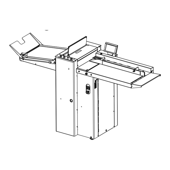
- Page 8 Digifold Pro DOCUMENT CREASING / FOLDING MACHINE Key to photograph below Delivery assembly Air separation knob Paper Gate Vacuum bleed knob Adjustable side lay Top Cover Suction slot knob Back stop Touchscreen Switch panel Fixed side lay Loading Table - Extension Air distribution knob Fuses (Optional)
-
Page 9: Section A ...... Covers
Digifold Pro SECTION A Covers: The Operator Side Door. The Operator Side Door cover which is situated adjacent to the operator, covers the Gap Set mechanism and Main Drive Pulley with its Belt. To remove this cover, first remove the two top fixing screws attaching the top plate, this must be lifted upwards to clear the gap set adjuster Knobs. -
Page 10: Control Cover And Top Cover
SECTION A The Control Cover The Control Cover fixes to the front of the machine and supports the control cover door hinge, with the door attached. To remove completely wiil give very little access to anything, however opening the door beneath the feed table gives access to the main electric controls. -
Page 11: Delivery Conveyor Removal
Digifold Pro SECTION A A.6 Delivery Conveyor To Remove the Delivery Conveyor the rear cover should be removed for access. Pivot the delivery down at 45 degrees using the handle on the end and turn the ‘delivery locking screw’ anti-clockwise to lock the delivery strut into this position. Shown in photo below. -
Page 12: Section B
SECTION B B.1 Valve Setting. Removal of Butterfly Valve Assembly. The Butterfly Valve assembly is located inside the rear cover at the back of the machine. To remove the valve Assembly first unplug the cable from its control board. Remove the two pipe mounting clip plates (ITEM 6 on next page) so that the hoses can be detached from the valve. -
Page 13: Valve Assembly Drawing
Digifold Pro SYSTEM Page 13... -
Page 14: Section C
SECTION C REMOVAL OF CREASING UNIT: The creasing mechanism Assembly is located in the middle of the machine and can Be accessed by opening the top cover. First, access should be gained by removing the ‘Rear Cover Assembly’ and ‘Top Cover Assembly’. - Page 15 Digifold Pro When re-assembling the Tilt Control Mechanism, it is important to make sure that when you re-engage the upper and lower worms (C), the pins (A) on the upper and lower worm wheel assemblies (D) are in the same relative position as shown above. This will ensure the throw of each eccentric is in the same position at the top and the bottom.
-
Page 16: Removal /Replacement Drive Belt
SECTION C REMOVAL/REPLACEMENT CREASING DRIVE BELT With the creasing mechanism out of the machine you can work on the bench to disassemble the unit. Remove the Blade/Anvil Assembly Unscrew the two countersunk head screws from the input and output guides and remove them. - Page 17 Digifold Pro BLANK PAGE SYSTEM Page 17...
-
Page 18: Section D
SECTION D LOADING TABLE Removal of the Loading Table Remove the SideLay with the two locking Knobs. Remove the Choke Bleed Valve knob and the Choke Locking Knob. Remove the Choke Bleed Valve center shaft by unscrewing the soc. set screw beneath the loading table. -
Page 19: Suction Drum Belt Removal/Replacement
Digifold Pro SECTION D SUCTION DRUM AND BELT REMOVAL \REPLACEMENT Remove feed bed and side guide. Remove choke shaft by unscrewing the soc set screw from underneath, using a 2.5mm A/F allen key. Remove the bearing center support plate by unscrewing the two cap head screws. Remove suction drum and belt. -
Page 20: Section E .......Infeed Roller Removal/Replacement
SECTION E REMOVAL/REPLACEMENT OF INPUT ROLLERS All side covers and the top cover should be removed to ease access to the infeed rollers. Remove the main creasing mechanism and tilt mechanism. TOP INPUT ROLLER Remove the lead edge sensor housing by unscrewing the two fixing screws from the rear of the machine and leave loose in situ. - Page 21 Digifold Pro Layedge Side Operator Side SYSTEM Page 21...
-
Page 22: Section F .......Replacing The Touchscreen Assembly
SECTION F Replacing the Touch Screen Assembly Ensure the mains power is turned off but with the plug in the socket, this maintains an earth to reduce static damage. 1. Open the hinged Control cover located beneath the feed bed and open the rear cover to expose the mounting. -
Page 23: Section G .......Electrics
SECTION G ELECTRICS: The PRO Control System. The Morgana PRO control system is essentially a computer system just like the PC you use at home. Unlike your Microsoft Windows PC, the PRO system uses a LINUX operating system and runs only one program, which is the machine control program for the particular machine that it is installed on. -
Page 24: Removal/Refitting Control Pcb And Prog Board
SECTION G ELECTRICS: REMOVAL/REFITTING PCB’s REPLACEMENT OF MAIN CONTROL P.C.B. This PCB controls all functions of the machine and houses the Main Program PCB. The use of an antistatic wrist band should be used during work on the main control PCB. Switch the mains power off and disconnect from the mains supply. -
Page 25: Installation Procedure
Digifold Pro Installation Procedure. 1. Note the current machine calibration settings. 2. Power down the machine and remove the power cord. 3. Change the USB Flash Drive (Red or Green depending on what is currently fitted). NOTE. It is important to choose the right colour in accordance with the machine you are upgrading. -
Page 26: Removal/Replacement Itx Boards
SECTION G ELECTRICS: REMOVAL/REFITTING PCB’s ITX BOARD REPLACEMENT. The ITX mother board supplies the graphics to the touch screen display, to remove.- 1. Switch the mains power off. 2. Cut cable ties and unplug the all plugs. 3. Unscrew the four fixing screws attaching the board to the plate and remove from the machine. -
Page 27: Removal/Replacement Stepper Drive Pcb
Digifold Pro SECTION G ELECTRICS: REMOVAL/REFITTING PCB’s REPLACEMENT OF STEPPER DRIVE BOARDS There is one Dual Stepper Driver Board, and three Single Stepper Driver Boards; which supply the drive motors with the correct power. These are located as above, and can be accessed in the same manner. Switch the mains power off and disconnect from the mains supply. -
Page 28: Entering Engineers Tools
SECTION G DIAGNOSTICS and CALIBRATION TOOLS. To enter the engineers tools menu. Turn the Machine on. Insert the Engineers Plug into the Socket located at the rear of the machine. Select Tools on the Display and continue to select required tool. SET THE TOTAL COUNT TO ZERO. - Page 29 Digifold Pro SECTION H Cleaning Sensors Lead Edge Sensor The lead edge sensor housing is located on the layedge side of the machine between the input roller shafts. With a slim brush the sensors can be cleaned when required. Pass the brush under the ball holder and push through until it passes the infeed rollers, as can be seen in the picture below.
- Page 30 SECTION H Changing Sensors Lead Edge Sensor The Lead edge sensor assembly is positioned just after the input rollers and is housed in a black delrin machined block. To check the operation of this sensor, insert a piece of paper between the rollers and feed by hand until the sensor is covered, at which point the Red LED3 will illuminate on the main control PCB.
- Page 31 Digifold Pro SECTION H Changing Sensors on the Folder unit Clip Sensors. There are two sets of Clip sensors and both are located just after a set of fold rollers. They act as machine cutouts in cases of malfunction within the folding cycle. Clip 1 &...
-
Page 32: Bottom Fold Knife
SECTION J REMOVING/ FITTING OF FOLD KNIFE ASSEMBLIES Remove the gap set assembly. Upper Fold Knife Remove the top curved guide by unscrewing the four posi pan head screws (2 each end). Loosen the sensor and allow to hang freely. Unscrew the two countersunk head screws (one each end) using a 4mm allen key and remove screws. - Page 33 Digifold Pro SECTION K Main Fold Rollers - Removal The folding unit has 3 main folding rollers that can be easily removed for replacement, the procedure for removing the rollers is as follows:- Rollers cannot be removed without removing the fold knives. Remove rear cover assembly and top guard.
- Page 34 SECTION K Main Fold Rollers - Removal Remove The 2nd Fold Roller Assembly as follows:- Remove the worm wheel from the shaft. Remove 3 off screws on access housing and 1 off on link plate. The roller assembly can now be withdrawn from the lay side of the machine. Remove The 1st Fold Roller Assembly as follows:- Remove 3 off screws on access housing.
-
Page 35: Main Fold Rollers - Replacement
Digifold Pro SECTION K Main Fold Rollers - Replacement. The main rollers should be fitted into the folding unit in the reverse order of removal. Procedure for replacing the rollers is as follows:- Replace The 1st Roller Assembly as follows:- Insert the roller assembly into the frame from the operator side of the machine. - Page 36 SECTION L Perforator Unit Replacing the Gas Strut To Replace the gas strut first assemble the bottom shoulder bolt into its location and tighten using a 3mm allen key. With the dog point located in the shaft mark the shaft and the link plate such that you are able to realign the dog of the socket set screw when required.
- Page 37 Digifold Pro BLANK PAGE SYSTEM Page 37...
- Page 38 Digifold Pro Engineering Set-Up & Calibration Techniques Generally, Pre-Power Set-Up is made much easier if the Top Cover and the Entry Guard are removed. An adequate supply of DigiFold Pro Test Sheets (Part Number 170-004-01) should be made available for many of the set-up procedures.
- Page 39 Digifold Pro SYSTEM Page 39...
-
Page 40: Section 1 .................Loading Table Alignment
Pre-Power Setup Procedure. The 'Pre-Power Procedure' does not require connection to the mains power supply so leave the machine disconnected if the covers have been removed. Loading Table Alignment:- The Loading Table Assembly effectively consists of the Loading Table itself, the Feed System & the Manifold Air Separation System which acts as the Fixed Sidelay for the initial alignment of the paper and therefore must be square to the input rollers. - Page 41 Digifold Pro It should be possible to visually check the parallel alignment of the lead edge of the 1.4. sheet with the Upper Input Roller. (See FIG.1.4). Fixed Side Lay (Manifold) Paper Upper Input Roller FIG.1.4 Lead Edge of Test Sheet If adjustment is required, loosen the two M8 Button Head Screws (see FIG.1.5 1.5.
-
Page 42: Section 2 .................Dynacrease Alignment
Dynacrease Alignment:- The DynaCrease Unit has an adjustable Tilt Mechanism to enable Crease squareness adjustments to be made by the operator allowing for variations in Print & Paper Stock. To ensure that the operator has the full range of adjustment available, this unit needs to be centralized square to the Side Lay (&... - Page 43 Digifold Pro Remove the Balls from the Sidelay 2.2. Open the Input Roller gap fully by releasing the Locking Screw and using the 4mm 2.3. hexagon key to move it down towards the Loading Table. (See FIG.2.3 below). Locking Screw FIG.2.3 Operator Side Place a Test Sheet on the Loading Table with its Lay Edge against the Fixed Side Lay &...
- Page 44 If adjustment is required, loosen the two outside M8 Cap Head Screws securing the 2.6. Upper Pivot Block to the Frame, the two inside M8 Cap Head Screws securing the Lower Pivot Block to the top of the Blade Drive Stepper Motor Mounting Plate & the two outside M8 Cap Head Screws securing the Lower Pivot Block to the Frame.
-
Page 45: Section 3 .................Belt Tension
Digifold Pro Belt Tension:- There are 5 Drive belts on the DigiFold Mechanism & 3 on the Delivery system. All Drive belts are XL Series Timing Belts of various widths and should be tensioned in accordance with the following notes. 3.1. - Page 46 Adjust the tension of the Blade Drive Belt on the DynaCrease Unit by loosening the four M5 3.5. fixings securing the Blade Drive Motor to the Stepper Mounting Plate. Access to these fixings is via the large clearance hole around the motor. Raise or lower the Motor until the correct tension is achieved &...
- Page 47 Digifold Pro 3.6. Adjust the tension of the Vacuum Drive Belt by loosening the four Cap Head fixings securing the Vacuum Drive Motor to the Vacuum Stepper Plate. Rotate the Motor about its top left hand fixing until the correct tension is achieved & tighten all fixings FIG.3.4A FIG.3.4B Vacuum...
-
Page 48: Section 4 ................Creasing Blade Installation
Creasing Blade Installation Creasing Blade & Anvil Sets are available in two sizes - Standard for sheets over 0.25mm thick & Narrow for sheets under 0.25. These figures are only a guide - good results can, in most cases, still be achieved outside a Blade Set's range - see Trouble shooting Guide for more information. - Page 49 Digifold Pro 4.5. Place a Test Sheet on the Loading Table with its Lay Edge against the Fixed Side Lay & slide it through the open Input Rollers until the lead edge has passed through the DynaCrease Unit but not into the Fold Rollers. 4.6.
- Page 50 Input Transfer Shaft Gear Mesh The Lower Input Roller is driven by a pair of gears off the Input Transfer Shaft. To ensure Creasing accuracy, these two gears must mesh perfectly with little or no backlash. (See FIG.5.0 below). Loosen the Grub Screw which secures the Layside Access Housing for the Lower Input 5.1.
- Page 51 Digifold Pro Upper Input Roller - Setting the Parallelism & Pressure The Upper Input Roller is gear driven from the Lower Input Roller & should be adjusted for parallelism & pressure to ensure sheets are correctly aligned and controlled On the Layside end of this roller, there is an eccentric housing which enables adjustment. The housing is secured to the shaft using two M5 flat tip set screws.
- Page 52 FIG.6.1.B Shaft Flats 80gsm Test Strips Adjust the Layside Housing, using the shaft flats on the operator side, until a light 6.2. pressure is felt on the operator strip & then temporarily tighten one of the housing set screws on the op side. (the top one). Now adjust the operator side housing, using the M5 cap head screw, to give a very 6.3.
- Page 53 Digifold Pro BLANK PAGE SYSTEM Page 53...
-
Page 54: Section 7 ................Fold Rollers - Setting The Parallelism & Pressure
Fold Rollers - Setting the Parallelism & Pressure There are four Fold Rollers, one of which is fixed (Ø45) and has no adjustments This roller acts as the datum for the remaining three Fold Rollers (Ø60) which all have parallelism & pressure adjustments to ensure sheets are correctly aligned and controlled On the Layside end of each roller is an eccentric housing which enables adjustment of the parallelism. - Page 55 Digifold Pro SYSTEM Page 55...
- Page 56 Perforator Assembly The Perforator Assembly also acts as an outfeed unit to ensure that sheets are successfully ejected onto the delivery. It is gear driven off the 3rd Fold Roller and held in position by a Gas Strut. (The assembly can be swung away from the paper path to make clearing paper jams easier.
- Page 57 Digifold Pro Swing the Perforator back up into its operating position, set roller gap 3 to be a loose 8.3. pull on an 80gsm strip and check the mesh between the Idler Gear on the Perforator Assembly & the Drive Gear on the 3rd (Top) Fold Roller. (remove the 4 securing screws to remove the cover for better access) The gear mesh can be adjusted by rotating the Layside eccentric Adjuster Cam after 8.4.
-
Page 58: Section 9 ................Setting The Fold Knives
Setting The Fold Knives. The Fold Knives are driven by a stepper motor and are controlled by a cam follower and cam profile. The position of the black delrin cam is critical as it controls the start & stop positions of the Fold Knives. - Page 59 Digifold Pro downwards until the jig assembly fits correctly, adjust the 9.4. Rotate the Delrin cam eccentric shaft if required, tighten the two cap head screws on the ends of the eccentric shaft. Remove the Right Hand Shoulder Bolt from the Setting Jig, rotate the Jig (and the Knife 9.5.
-
Page 60: Section 10 ..............Adjusting The Top Cover Safety Switch
10. Adjusting The Top Cover safety Switch 10.1. Open layside door. 10.2. Loosen the two fixings on the switch. 10.3 Adjust the switch position until lifting the top cover switches the machine when lifted by 6mm - 10mm. Page 60 CREASING / FOLDING... - Page 61 Digifold Pro SYSTEM Page 61...
- Page 62 Powered Setup Procedure. The "Powered Set-Up Procedure" does require connection to the Mains Power Supply so please ensure that all Covers & Guards are replaced & secure before proceeding. Adjustments to the Control System & Circuit Boards should only be carried out by fully trained & qualified personnel.
-
Page 63: Section 12 .............Fold Roller Gap Potentiometers
Digifold Pro Fold Roller Gap Potentiometers:- The Fold Roller Gaps are controlled by a mechanism which uses potentiometers to measure their positions. This information is then available to the Operator on the Gap Set Screen. These 3 Pots, which are located at the bottom of the Gap-Set Mechanism on the Operator Side of the machine, will all require calibrating:- Enter the Gap-Set Screen by operating the Touch screen. -
Page 64: Section 13 .............Dynacrease Tilt Potentiometer
DynaCrease Tilt Potentiometer:- The Dynacrease Tilt is controlled by a mechanism which uses a potentiometer to measure its position. This information is then available to the Operator on the Main Display Screen. This Pot, which is located at the bottom of the Tilt Mechanism on the Operator Side of the machine, will require calibrating:- Remove the Balls from the Sidelay. -
Page 65: Section 15 ............Sensors And Detectors
Digifold Pro Repeat this procedure from 14.3 until the desired result is achieved and then 14.5. return to the Run Screen. With the motors running, operate the Compressor Switch to start the Compressor. 14.6. From the Run Screen start the Vacuum Drum & Suction. Hold a Test Sheet over the drum (do not allow the sheet to be fed) &... - Page 66 Crunch Sensor uses a beam projected across the machine just in front of the blade and above the paper path, when the beam is broken the machine will stop. The receiver is housed in the Side Plate of the machine and is on the Operator Side, whilst the transmitter is housed in the Side Plate of the machine on the Lay Side.
-
Page 67: Section 16 ............Delivery Assembly
Digifold Pro Delivery Assembly The Delivery Assembly is there to provide a moving platform for the processed sheets to collect onto once finished. It consist of 2 main components, the delivery belt, and the delivery roller. Delivery Belt 16.1. To set the delivery Belt tension correctly it is imperative that the 2 'Roller Drive Belts' are first loosened to prevent excessive loads to the drive roller bearings. - Page 68 Ensure the eccentric idlers are rotated to give little or no tension to the delivery 16.1.4. roller drive belts. Eccentric Idler (1 Each Side) FIG.16.1.4 Raise the delivery until it is fully up (ensure the gearbox is engaged first). 16.1.5. Turn on the 'System Switch'.
- Page 69 Digifold Pro The 'Delivery Roller' drive belts need to be tensioned correctly (see previous section). NOTE - When adjusting the tension of the Lay Side 'Delivery Roller Drive Belt', notice that you are also providing the tension for the motor drive for this roller. Delivery Roller Squareness 16.2.1.
- Page 70 16.2.2. Delivery Potentiometer To position the roller correctly there is a potentiometer which provides the feedback to the processor. In order to set this correctly, you must follow this procedure; 16.2.2.1. Raise the delivery until it is fully up . 16.2.2.2.
- Page 71 Digifold Pro 6.2.2.5. Whilst holding the belt away from the pulley carefully rotate the potentiometer pulley until it reaches the end of its travel. 16.2.2.6. Continue to hold the belt away from the pulley and rotate the potentiometer pulley in the opposite direction for a full 5 turns (use a mark for reference if required).
- Page 72 NOTE - It may be necessary to re-tension the layside delivery roller drive belt. If so, do that now before proceeding to the next step. 16.2.2.10. See section 20. for calibration of the delivery roller. 16.3. Delivery Damping For the delivery to raise and lower correctly it is necessary to set the damping level of the supporting Gas strut that keeps it in position.
- Page 73 Digifold Pro SYSTEM Page 73...
-
Page 74: Section 17 .............Primary Fold Setup
Crease & Fold Setup Procedure Having completed the Pre-powered and Powered setup the digifold needs to have the crease and fold positions calibrated. This is primarily conducted using software adjustments within the 'tools' menu, however, during this process you may need to re- adjust the creasing matrix and Upper input roller in accordance with the descriptions stated below. -
Page 75: Section 18 .............Crease Setup
Digifold Pro Crease Setup Parallelism 18.1. The first part of this process confirms if the sheet steering has been corrected by checking the parallelism of the creases produced. If the creases are not parallel, then the upper input roller should be adjusted to compensate. (See FIG.18.1). Feed Direction Crease 3 Crease 1... - Page 76 NOTE - that although this procedure may have already been performed, it is critical the creases are parallel, even if this means the 'Fold in Half' test performed previously in the fold setup, is compromised slightly. To adjust the upper input roller follow this procedure. Loosen the two Operator side housing screws (M5 set screws).
-
Page 77: Section 19 .............Squareness
Digifold Pro Squareness Ensure the 'tilt' is set to zero, and the 'Dynacrease' mechanism has been set square to the input rollers (see Pre-powered Setup). Using a test sheet, and keeping the sheet edge in contact with the fixed sidelay, manually feed the sheet through the input rollers and the creasing blades until the sheet can be seen just protruding from them. - Page 78 Crease Bias Crease bias is necessary to ensure the pre-programmed fold types give the best results. NOTE - The creasing matrix must be installed with the blade at the top, and test stock MUST be used. Do not used damaged test stock. To setup the crease bias, use the following procedure;...
- Page 79 Digifold Pro SYSTEM Page 79...
-
Page 80: Section 21 .............Delivery Roller
Calibration This is the final calibration procedure and closely follows the 'Calibration' flow chart. You must have completed all previous setup procedures leading up to this final calibration. If additional information is required for setting up the various crease and fold variations, please refer to the operators manual. -
Page 81: Section 24 .............Deflect Adjustments
Digifold Pro Deflect Adjustments The deflect trims need to be calibrated to allow the sheet to pass through the machine without damaging the lead edge. 24.1 K1 Double Deflect Trim In the tools menu Conduct this test with K2 turned off using the 'Tools' menu. If marking occurs on K1 then follow these general rules. -
Page 82: Section 25 .............Follow Stretch
Follow Stretch For creases that take place and don't allow for the creasing blades to stop in between, an extra setting is required to account for roller diameter variations. Setup 'Crease Only' at 100, 170, 240, 310 and 370. Check the crease positions are pitched out correctly. - Page 83 Digifold Pro Section M Trouble Shooting Creasing Fault Reason Solution Erratic register of Too heavy crease profile. Adjust Blade depth to the creaser lower the pressure. Roller gap settings incorrect check with 80 gsm. adjust. (better to set tighter to drive) Damaged roller surface.
- Page 84 FAULT:- ‘NO SYNC’ appears on touchscreen. (Machine will not boot up). 1. CHECK THE ATX POWER SUPPLY AS FOLLOWS:- (i) Disconnect the 20/24 way ATX power supply connector from the ITX Motherboard. (ii) Using a piece of tinned copper wire, short out the GREEN and BLACK wires of the connector as shown in FIG.1 below FIG.1 TINNED COPPER WIRE LINK...
- Page 85 Digifold Pro PINS 3 & 4 FIG.2 IMPORTANT RECYCLING NOTE:- The ITX mother board has a lithium battery fitted, the board together with its battery must be in compliance with agreed national Procedures Please contact your local disposal recycled authority for information CAUTION.
- Page 86 Check 500mA fuse, below the Mains Input connector (See Page 90). IMPORTANT. If this fuse has blown replace it must be replaced with a T500mA fuse, Morgana part number 681-020. Is there a V DC output from the ATX PSU? (See page 84). Replace the ATX PSU.
- Page 87 Anti-static Transformer. FUSE YELLOW ORANGE T315mA Morgana Systems Ltd PUMP OVERLOAD BOARD WHITE WHITE If this fuse has blown it must be replaced with a T315mA fuse, Morgana part number 681-011. For Error messages see Operators Manual SYSTEM Page 87...
- Page 88 Section N Page 88 CREASING / FOLDING...
- Page 89 Digifold Pro 2 PSU ASSY. (76-272) 21 ENGINEERING LEAD (144-116) 3 DRIVE SIGNAL LEAD (173-56-01) 25 SENSOR BAR ASSY. (175-11-03) 4 BLADE SIGNAL LEAD (76-269) 26 SENSOR BAR ASSY. (175-11-01) 5 DELIVERY INPUT CONNECTOR LEAD (76-261) 27 HOME SLOT SENSOR LEAD (173-57-01) 6 SYSTEM SWITCH COIL LEAD (75-364) 28 VACUUM SLOT SENSOR LEAD (173-58-01) 7 DOUBLE SHEET DETECTION LEAD (75-354)
-
Page 90: Fuse Positions & Ratings
FUSE POSITIONS & RATINGS PSUs (24V & 48V) TRANSFORMER ASSY. T6.3AH 250V (681-019) T500mAH 250V (681-020) MAINS IN ANTI-STATIC UNIT F15AH 250V (652-047) T315mAH 250V (681-011) SPARE FUSE POSITION Page 90 CREASING / FOLDING... -
Page 91: Optional Double Sheet Detect Kit
Digifold Pro Optional Double Sheet Detect Kit (172-03-02). The optional Double Sheet Detect Kit, 172-03-02 , should be fitted in accordance with the installation instruction sheet 170-012-02 The double sheet detect feature can be turned ON or OFF as follows:- 1. - Page 92 REVISION HISTORY Rev. Mod No. Mod Description Date Mod By Page 92 CREASING / FOLDING...
Need help?
Do you have a question about the Digifold Pro CB and is the answer not in the manual?
Questions and answers