Table of Contents
Advertisement
Advertisement
Table of Contents

Related Manuals for Galaxy DX 949


Summary of Contents for Galaxy DX 949
-
Page 2: Table Of Contents
TABLE OF CONTENTS DX 949 CHAPTER 1 PAGE SPECIFICATIONS General.......... -
Page 3: Specifications
CHAPTER 1 SPECIFICATIONS DX 949 1.0 GENERAL Model DX 949 Frequency Range 26.965 - 27.405MHz. Emission Modes AM/USB/LSB Frequency Control Phase Lock Loop (PLL) synthesizer. ± 0.005 %. Frequency Tolerance ± 0.001 %. Frequency Stability Operating Temperature Range -30°C to +50°C. -
Page 4: Operation
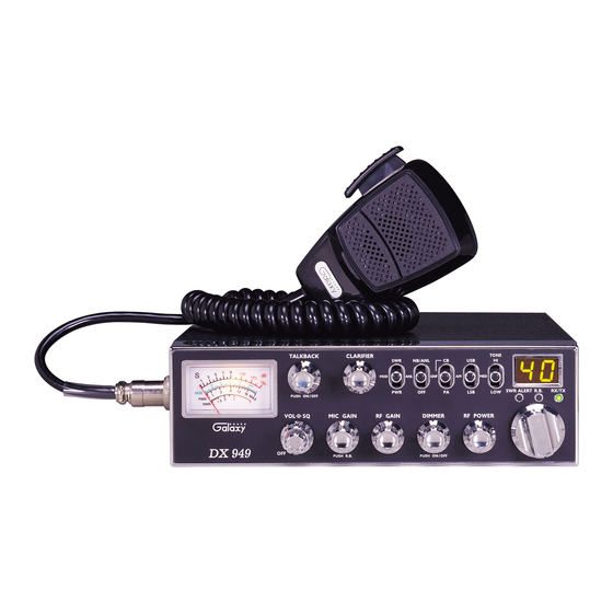
DX 949 Figure 2-1 Front Panel 2.0 INTRODUCTION This section explains the basic operating procedures for the Galaxy DX 949 mobile transceiver. 2.1 CONTROL AND CONNECTIONS 2.1.1 FRONT PANEL Refer to the above Figure 2-1 for the location of the following controls. - Page 5 Adjusts the microphone gain in the transmit and PA modes. This controls the gain to the extent that full talk power is available several inches away from the microphone. In the Public Address (PA) mode, the control functions as the volume control. Pushing this knob turns the Roger Beep on and off.
-
Page 6: Rear Panel
The radio does not operate when you are in the PA mode. The CB mode is normal operation of the radio. In the GNF mode, you are in CB operation but the Galaxy Noise Filter is engaged. This is a special noise filter that de-emphasizes audio high frequency response in order to increase the signal-to-noise ratio of weak signals. -
Page 7: Frequency Chart
The black goes to negative and the red goes to positive. 3. FREQUENCY COUNTER CONNECTOR This connector is for the optional Galaxy FC 347 six digit frequency counter. All connections are made through this connector. No soldering is required. - Page 8 CHANNEL CHANNEL FREQUENCY CHANNEL CHANNEL FREQUENCY 26.965 27.215 26.975 27.225 26.985 27.255 27.005 27.235 27.015 27.245 27.025 27.265 27.035 27.275 27.055 27.285 27.065 27.295 27.075 27.305 27.085 27.315 27.105 27.325 27.115 27.335 27.125 27.345 27.135 27.355 27.155 27.365 27.165 27.375 27.175 27.385 27.185...
-
Page 9: Microphone
The receiver and transmitter are controlled by the push-to-talk switch on the microphone. Press the switch and the transmitter is activated, release switch to receive. When transmitting, hold the microphone two inches from the mouth and speak clearly in a normal voice. The radio comes complete with low impedance (500 ohm) dynamic microphone. - Page 10 Pin Number Mic Cable Lead Audio Shield Audio Lead Transmit Control Receive Control Figure 2-3 Your Transceiver Microphone Schematic If the microphone to be used is provided with pre-cut leads, they must be revised as follows : (i) Cut leads so that they extend 7/16” beyond the plastic insulating jacket of the microphone cable. (ii) All leads should be cut to the same length.
-
Page 11: Chapter 3
To wire microphone cable to the plug provided, proceed as follows : (i) Remove the retaining screw. (ii) Unscrew the housing from the pin receptacle body. (iii) Loosen the two cable clamp retainer screws. (iv) Feed the microphone cable through the housing, knurled ring and washer as shown Figure 2-4. (v) The wires must now be soldered to the pins as indicated in the above wiring tables. -
Page 12: Introduction
DESCRIPTION DX 949 3.0 INTRODUCTION This section explains the technical theory of operation for the Galaxy DX 949 mobile transceiver. 3.1 PLL CIRCUIT The Phase Lock Loop (PLL) circuit is responsible for developing the receiver’s first local oscillator signal and the transmitter’s exciter signal. The PLL circuit consists primarily of IC2, IC3, Q25, Q27, Q28 and Q61. - Page 13 DX 949 CIRCUIT DIAGRAM - 12 -...
-
Page 14: Chapter 4
CHAPTER 4 - 13 -... -
Page 15: Alignment
DX 949 ALIGNMENT 4.0 REQUIRED TEST EQUIPMENT DC Power Supply (13.8VDC, 10A) Frequency Counter (100 MHz) RF Wattmeter (25~60 MHz, 25W) RF Signal Generator (100 MHz) Multimeter Automatic Distortion Meter Automatic Modulation Meter Oscilloscope (50 MHz) Audio Signal Generator Sinad Meter 4.1 ALIGNMENT PROCEDURES... -
Page 16: Transmitter Alignment
4.1.2 TRANSMITTER ALIGNMENT ITEM U.U.T. SETTING ADJUST MEASUREMENT POINT BIAS Current Set radio to CH 19 USB TX mode. MOD off. Connect current meter to TP7(+) and TP9(-) VR12 50 mA Connect current meter to TP7(+) and TP8(-) VR10 100 mA SSB TX Power Set radio to CH 19, USB TX mode. - Page 17 ITEM U.U.T. SETTING ADJUST MEASUREMENT POINT AM Sensitivity Set radio to CH 19 AM RX MODE. L2, L3, L5, Audio output > 2V Clarifier setting at 12 o’clock. L6, L7, L8, S/N 10 dB RF Gain fully clockwise, L9, L10 SQ fully counter clockwise.
- Page 18 Figure 4-2 Receiver test setup - 17 -...
-
Page 19: Chapter 5
Figure 4-3 Main PCB Adjustment Locations CHAPTER 5 - 18 -... -
Page 20: Maintenance
MAINTENANCE DX 949 5.0 PRECAUTIONS The inherent quality of the solid-state components used in this transceiver will provide many years of continuous use. Taking the following precautions will prevent damage to the transceiver. (i) Never key the transmitter unless an antenna or suitable dummy load is connected to the antenna receptacle. -
Page 21: Pcb Layout & Part List
DIAGRAMS & DX 949 PARTS LIST 6.0 GENERAL Information on most electrical and mechanical parts is included in the parts list. The reference designators are in alphanumeric order. PART LIST: DX 949 VR P.C.B ITEM REFERENCE RANGER PART DESCRIPTION NUMBER NUMBER EPT095950Z VR P.C.B. - Page 22 PART LIST : DX 949 ANT P.C.B ITEM REFERENCE RANGER PART DESCRIPTION NUMBER NUMBER EPT360042Z ANT P.C.B. RCY010004Z 0 ohm 0.1W RCY014714Z 470 ohm 0.1W R3,R4 RCY011014Z 100 ohm 0.1W RCY013314Z 330 ohm 0.1W R5,R11 RCY011024Z 1K ohm 0.1W RCY012224Z 2.2K ohm 0.1W...
- Page 23 - 22 -...
- Page 24 PART LIST : DX 949 ROTARY SW P.C.B ITEM REFERENCE RANGER PART DESCRIPTION NUMBER NUMBER EPT094920Z ROTARY SW P.C.B. R202,R204-R217 RCY011024Z 1K ohm 0.1W Q201 TY2SC2712G TR 2SC2712 ROTARY SW EWRT32000S ROTARY SW J7,J9,J10 EX07N48223 PCB C/S 2P EX07N48234 PCB C/S 2P...
- Page 25 PART LIST : DX 949 MIC P.C.B ITEM REFERENCE RANGER PART DESCRIPTION NUMBER NUMBER EPT690050Z MIC P.C.B. C501,C502,C503,C504 CC0501027L 0.001µF 50V C505,C506 CC0501037L 0.01µF 50V Q501 TDTA0124ES T/R DTA124ES L501 ECCHK16001 CHOKE COIL 5.6µH L502 ECBAD18526 BEAD COIL MIC PCB...
- Page 26 PART LIST : DX 949 METER P.C.B ITEM REFERENCE RANGER PART DESCRIPTION NUMBER NUMBER EPT055V51Z METER P.C.B. RCP166824Z 6.8K ohm 1/16W RCP163934Z 39K ohm 1/16W RCU143904Z 39 ohm 1/4W RCU141024Z 1K ohm 1/4W RCU144724Z 4.7K ohm 1/4W RCU141034Z 10K ohm 1/4W RCM144724B 4.7K ohm 1/4W...
- Page 27 PART LIST : DX 949 BAND P.C.B ITEM REFERENCE RANGER PART DESCRIPTION NUMBER NUMBER EPT095940Z BAND P.C.B. VOL/SQ RV50303522 VR 50KB/50KA W/SW RF GAIN RV10203528 VR 1KB DIM ON/OFF RV50203542 5KB/PUSH SW MIC/R.B ON RV10203541 1KA/PUSH SW RF POWER RV50203525 VR 5KB BAND P.C.B.
- Page 28 PART LIST : DX 949 DISPLAY P.C.B ITEM REFERENCE RANGER PART DESCRIPTION NUMBER NUMBER EPT094930Z DISPLAY P.C.B. DISPLAY P.C.B. EX03N40483 LED DISPLAY R325,R326 RCY011024Z 1K ohm 0.1W C501 CK1103AB6U 0.01µF 50V EX01Y40116 LED LAMP EX01Y40117 LED LAMP EX01Y40114 LED LAMP...
- Page 29 DX 949 MAIN PCB. REMARK: SOLDER SIDE (WHITE) - 28 -...
- Page 30 C218 CC0500301L 3PF 50WV PART LIST CC0500501L 5PF 50WV DX 949 MAIN PCB C1,49,108,147 CC0501004L 10PF 50WV CC0501804L 18PF 50WV CC0502704L 27PF 50WV REFERENCE RANGER DESCRIPTION C287 CC0503304L 33PF 50WV NUMBER PART NO. CC0508204L 82PF 50WV EPT069610Z MAIN P.C.B C4,70...
- Page 31 C13,21,22,44,82,115, CE0251067Z 10UF 25WV ECSPG18001 0.8x3.5x7t 132,158,275,276,239 ECRFZ10048 25UH C80,181 CE0252267Z 22UF 25WV L39,41,13 ECBAD18526 3.5x6x1.2 C33,37,144,175 CE0254767Z 47UF 25WV VR7,12,16,18 RE10200041 1K VM6CK PV C156,238,293,107 CE0161077Z 100UF 16WV VR13,14 RE50200042 5K VM6CK PV C152,179 CE0163377Z 330UF 16WV VR1,2,6,17 RE10300031 10K VM6CK PV CE0104777Z 470UF 10WV...
- Page 32 ENTA07222A TA7222AP T2SB00754Y 2SB754Y T2SC02166C 2SC2133C T2SC01969C 2SC1969C T2SA01869Z 2SA1869 - 31 -...
-
Page 33: Updates And Corrections
- 32 -... - Page 34 AT0949040A - 33 -...
- Page 35 - 34 -...
Need help?
Do you have a question about the DX 949 and is the answer not in the manual?
Questions and answers