Table of Contents
Advertisement
Advertisement
Table of Contents

Related Manuals for Galaxy DX 979


Summary of Contents for Galaxy DX 979
- Page 1 CB Radio Model DX Service Manual Copyright Reserved...
-
Page 2: Table Of Contents
TABLE OF DX 979 CONTENTS PAGE CHAPTER 1 SPECIFICATIONS General .............. -
Page 3: General
CHAPTER 1 DX 979 SPECIFICATIONS 1.0 GENERAL Model DX 979 Channels Frequency Range 26.965 – 27.405 MHz Emission Modes AM/USB/LSB Frequency Control Phase Lock Loop (PLL) synthesizer Frequency Tolerance 0.005 % Frequency Stability 0.001 % Operating Temperature Range -30°C to +50°C Dynamic PTT, 500 Ω... -
Page 4: Control & Connections
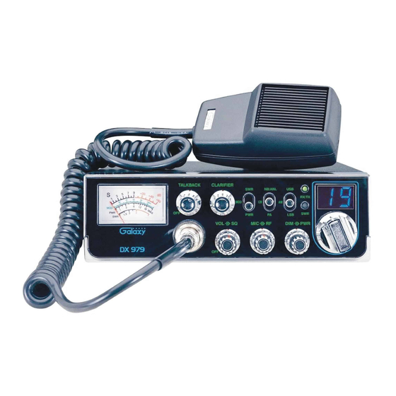
DX 979 Figure 2-1 Front Panel 2.0 INTRODUCTION This section explains the basic operating procedures for the DX 979 mobile CB radio. 2.1 CONTROLS AND CONNECTIONS 2.1.1 FRONT PANEL Refer to the above Figure 2-1 for the location of the following controls. - Page 5 5. MIC GAIN CONTROL: Adjusts the microphone gain in the transmit and PA modes. This controls the gain to the extent that full talk power is available several inches away from the microphone. In the Public Address (PA) mode, the control functions as the volume control. 6.
-
Page 6: Rear Panel
4. EXT. SP: This jack accepts a 4 to 8 ohm, 5 watt external speaker. When the external speaker is connected to this jack, the built-in speaker will be disabled. 5. F.C.: This jack is used to connect the optional Galaxy FC347 six-digit frequency counter. All connections, including DC power, are provided to the FC347 through this jack. - Page 7 2.1.3 FREQUENCY CHART CHANNEL CHANNEL FREQUENCY CHANNEL CHANNEL FREQUENCY (MHz) (MHz) 26.965 27.215 26.975 27.225 26.985 27.255 27.005 27.235 27.015 27.245 27.025 27.265 27.035 27.275 27.055 27.285 27.065 27.295 27.075 27.305 27.085 27.315 27.105 27.325 27.115 27.335 27.125 27.345 27.135 27.355 27.155 27.365...
-
Page 8: Microphone
2.2 MICROPHONE The receiver and transmitter are controlled by the push-to-talk switch on the microphone. Press the switch and the transmitter is activated, release the switch to receive. When transmitting, hold the microphone two inches from your mouth and speak clearly in a normal voice. The radio comes complete with a low impedance (500 ohm) dynamic microphone. -
Page 9: Alternate Microphones And Installation
2.4 ALTERNATE MICROPHONES AND INSTALLATION For best results, the user should select a low impedance dynamic type microphone or a transistorized microphone. Transistorized type microphones have a low output impedance characteristic. The microphones must be provided with a four-lead cable. The audio conductor and its shielded lead comprise two of the leads. -
Page 10: Pll Circuit
DX 979 DESCRIPTION 3.0 INTRODUCTION This section explains the technical theory of operation for the DX 979 mobile CB radio. 3.1 PLL CIRCUIT The Phase Lock Loop (PLL) circuit is responsible for developing the receiver’s first local oscillator signal and the transmitter’s exciter signal. The PLL circuit consists primarily of IC2, IC3, Q25, Q29 and Q28. - Page 11 - 10 -...
-
Page 12: Alignment Procedures
CHAPTER 4 DX 979 ALIGNMENT 4.0 REQUIRED TEST EQUIPMENT DC Power Supply (13.8VDC, 10A) Frequency Counter (100 MHz) RF Wattmeter (10W) RF Signal Generator (100 MHz) Multi-meter Automatic Distortion Meter Automatic Modulation Meter Oscilloscope (50 MHz) Audio Signal Generator Sinad Meter 4.1 ALIGNMENT PROCEDURES... - Page 13 4.1.2 TRANSMITTER ALIGNMENT ADJUST ITEM U.U.T. SETTING MEASUREMENT POINT BIAS Current Set radio to CH 19 USB TX mode. Modulation Off. Remove “short PCB” from TP7, TP8, TP9. Connect current meter to TP7(+) and TP9 (-) VR12 50 mA Connect current meter to TP7(+) and TP8 (-) VR10 100 mA SSB APC...
- Page 14 4.1.3 RECEIVER ALIGNMENT ADJUST ITEM U.U.T. SETTING MEASUREMENT POINT AM Sensitivity Set radio to CH 19 AM RX mode. Set RF GAIN Fully Clockwise. L2,L3,L5,L6, Audio Output > 2V Set SQ Fully Counter Clockwise. L7,L8,L9,L10 S/N > 10 dB. Set VOL Control at 2 o’clock. Set NB/ANL switch to OFF position.
- Page 15 Figure 4-1 Transmitter test setup Figure 4-2 Receiver test setup - 14 -...
- Page 16 DX 979 MAIN PCB ADJUSTMENT LOCATION DRIVER BIAS FINAL BIAS RF METER AM LOW POWER AM HI POWER AM LOW POWER AM MOD METER SSB S-METER AM S-METER 10.240 MHz ADJUST CARRIER BALANCE SSB SQUELCH AM SQUELCH TX OFFSET - 15 -...
-
Page 17: Periodic Inspection
CHAPTER 5 DX 979 MAINTENANCE 5.0 PRECAUTIONS The inherent quality of the solid-state components used in this transceiver will provide many years of continuous use. Taking the following precautions will prevent damage to the transceiver. (i) Never key the transmitter unless an antenna or suitable dummy load is connected to the antenna receptacle. - Page 18 CHAPTER 6 DIAGRAMS & DX 979 PARTS LIST 6.0 GENERAL Information on most electrical and mechanical parts is included in the parts list. The reference designators are in alphanumeric order. - 17 -...
- Page 19 DX 979 ROTARY SWITCH PCB (EPT092920Z) (SMD-COPPER SIDE) ( COMPONENT SIDE ) - 18 -...
- Page 20 PART LIST: DX 979 ROTARY SW. P.C.B REFERENCE RANGER PART ITEM DESCRIPTION NUMBER NUMBER EPT092920Z ROTARY SW PCB CHIP/F/R 0.0 Ω 0.1W R207,R210,R218 RCY010004Z CHIP/F/R 330 Ω 0.1W RCY013314Z R201 CHIP/F/R 680 Ω 0.1W R202,R203,R204,R205, RCY016814Z R206 CHIP/F/R 4.7K Ω 0.1W...
- Page 21 DX 979 DISPLAY PCB (EPT092930Z) ( COMPONENT SIDE ) ( COMPONENT SIDE ) ( COPPER SIDE ) - 20 -...
- Page 22 PART LIST: DX 979 DISPLAY P.C.B REFERENCE RANGER PART ITEM DESCRIPTION NUMBER NUMBER EPT092930Z DISPLAY PCB CHIP/F/R 680 Ω 0.1W R301,R302,R303,R304, RCY016814Z R305,R306,R307 CHIP/F/R 1K Ω 0.1W R308 RCY011024Z D301,D302 EDSS00355Y DIODE 1SS355 LED201,LED202 EX01Y40114 LED LAMPS KM-23ESGC DISPLAY EX03N40419...
- Page 23 DX 979 (DIM-PWR/MIC-RF/VOL-SQ CONTROL) VR PCB (EPT092940Z) ( COMPONENT SIDE ) ( COPPER SIDE ) - 22 -...
- Page 24 PART LIST: DX 979 DIM-PWR/MIC-RF/VOL-SQ CONTROL, VR P.C.B REFERENCE RANGER PART ITEM DESCRIPTION NUMBER NUMBER EPT092940Z VR PCB CHIP/F/R 6.8K Ω 0.1W R402 RCY016824Z CHIP/F/R 10K Ω 0.1W R401 RCY011034Z C401,C402 CK1102AB5X CHIP/C .001uF 50VW C403,C404 CK1103AB5X CHIP/C .01uF 50VW...
- Page 25 DX 979 (TALKBACK/CLARIFIER CONTROL) VR PCB (EPT092950Z) ( COMPONENT SIDE ) ( COPPER SIDE ) PART LIST: DX 979 TALKBACK/CLARIFIER CONTROL, VR P.C.B REFERENCE RANGER PART ITEM DESCRIPTION NUMBER NUMBER EPT092950Z TB PCB VR501 (CLARIFIER) RV10203528 VR 1KB VR502 (TALKBACK)
- Page 26 DX 979 METER PCB (EPT092961Z) ( COMPONENT SIDE ) ( COPPER SIDE ) ( COPPER SIDE-SMD ) - 25 -...
- Page 27 PART LIST: DX 979 METER PCB (Dimmer Circuit) REFERENCE RANGER PART ITEM DESCRIPTION NUMBER NUMBER EPT092961Z METER PCB CHIP/F/R 15 Ω 0.1W R603 RCY011504Z CHIP/F/R 47 Ω 1/4W R606,R607 RCY144704Z R610 RCY011024Z CHIP/F/R 1KΩ 0.1W R605 RCY013324Z CHIP/F/R 3.3KΩ 0.1W...
- Page 28 DX 979 ANTENNA PCB (EPT360042Z) (COPPER SIDE-SMD ) ( COPPER SIDE ) ( COMPONENT SIDE ) PART LIST: DX 979 ANT P.C.B REFERENCE RANGER PART ITEM DESCRIPTION NUMBER NUMBER EPT360042Z ANT P.C.B RCY010004Z 0 OHM 0.1W RCY014714Z 470 OHM 0.1W...
- Page 29 DX 979 MAIN PCB (EPT092913Z) ( COMPONENTS SIDE ) - 28 -...
- Page 30 DX 979 MAIN PCB (EPT092913Z) ( COPPER SIDE ) - 29 -...
- Page 31 PART LIST DX 979 MAIN PCB REFERENCE RANGER DESCRIPTION C137 CC0501515L 150PF 50WV NUMBER PART NO. C31,136 CC0502715L 270PF 50WV C11,14 CC0503315L 330PF 50WV EPT092913Z MAIN PCB CC0505615L 560PF 50WV EPT120060A DCB+ PCB C52,197 CC0500101A 1PF 50WV 0 Ω 1/16W...
- Page 32 276,132,239 ECCHK16096 470UH CV038200AZ TRIMMER/C L503 ECCHK16000 0.47UH L26,27,46 ECCHK16003 470UH (CV38D2001) ECCHK16004 1.1MH EI-19 C80,181 CE0252267Z 22UF 25WV L33,37 ECCHK16070 22UH C37,175,33,144,38 CE0254767Z 47UF 25WV ECCHK16176 4.7UH C156,238,293,107 CE0161077Z 100UF 16WV ECCHK16246 22UH C252 CE0162277Z 220UF 16WV L28,30 ECSPG18003 SPRING COIL C152,179 CE0163377Z...
- Page 33 DX 979 SCHEMATIC DIAGRAM (CONTROL PCB)
- Page 34 DX 979 SCHEMATIC DIAGRAM (MAIN PCB)
- Page 35 DX 979 EXPLODE DRAWING DX 979 MECHANICAL PART...
- Page 36 UPDATES & CORRECTIONS Any updates or corrections to this Service Manual will be included in the Tech Support section of our website at www.GalaxyRadios.com.
- Page 37 Two Year Warranty This new Galaxy radio is covered by a two year limited warranty. Here are the details. • All of our Galaxy radio model numbers begin with the letters “DX” and are covered by our Limited Two Year Parts and Labor Warranty.
- Page 38 ATS979010A July, 2003...
Need help?
Do you have a question about the DX 979 and is the answer not in the manual?
Questions and answers