Table of Contents
Advertisement
Garden Treasures® is a registered trademark
of LF, LLC. All Rights Reserved.
ATTACH YOUR RECEIPT HERE
Serial Number
Questions, problems, missing parts? Before returning to your retailer, call our customer
service department at 1-800-643-0067, 8 a.m. - 8 p.m., EST, Monday - Friday.
EB14167
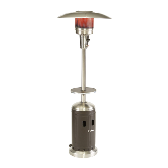
GAS PATIO HEATER
Purchase Date
1
ITEM #0574423
MODEL #PG171H-B
Français p. 19
Español p. 37
Advertisement
Table of Contents

Subscribe to Our Youtube Channel
Related Manuals for Garden Treasures Living PG171H-B


Summary of Contents for Garden Treasures Living PG171H-B
- Page 1 ITEM #0574423 GAS PATIO HEATER MODEL #PG171H-B Français p. 19 Español p. 37 Garden Treasures® is a registered trademark of LF, LLC. All Rights Reserved. ATTACH YOUR RECEIPT HERE Serial Number Purchase Date Questions, problems, missing parts? Before returning to your retailer, call our customer service department at 1-800-643-0067, 8 a.m.
-
Page 2: Table Of Contents
TABLE OF CONTENTS Product Specifications…….....................3 Package Contents……......................4 Hardware Contents……......................5 Preparation……..……….......................5 Safety Information……......................6 Assembly Instructions…….....................8 Operating Instructions……....................13 Care and Maintenance……....................15 Troubleshooting……......................17 Warranty……........................17 Replacement Parts List……....................18 WARNING DANGER Do not store or use gasoline or other FOR YOUR SAFETY flammable vapors and liquids in the If you smell gas: vicinity of this or any other appliance. -
Page 3: Product Specifications
PRODUCT SPECIFICATIONS Certification Height Overall 86.6 inches Reflector Diameter 31.5 inches Rated Heat Input 45,000 BTU/HR Fuel Propane-LP Gas Supply 20-Lb LP-Gas Cylinder Manifold Pressure 11 inches W.C. Injector Size (Diameter) 2.07 mm Safety Features Thermocouple & Tilt Switch Gas Supply Pressure Max 150 PSI, Min 5 PSI... -
Page 4: Package Contents
PACKAGE CONTENTS PART DESCRIPTION QUANTITY PART DESCRIPTION QUANTITY Top Dome Deck Ring KD Dome Cylinder Assembly Burner Assembly Base Pole Assembly Wheel Assembly Table Cover Table Support Assembly... -
Page 5: Hardware Contents
HARDWARE CONTENTS ST 4.2X8mm M5 X 10 M5 X 8 m M8X15mm M8 x 15 mm M5 x 8 mm M8 Nut M8 Nut Battery ST 4.2 x 8 mm M6 x 10 mm Battery screw Bolt Bolt Bolt Qty.2 Bolt Black Bolt Qty. -
Page 6: Safety Information
SAFETY INFORMATION Please read and understand this entire manual before attempting to assemble, operate or install the product. CALIFORNIA PROPOSITION 65 WARNING: Chemicals known to the state of California to cause cancer, birth defects or other reproductive harm are created by combustion of propane. The installation must conform with local codes or, in the absence of local codes, with the National Fuel Gas Code, ANSI Z223.1 /NFPA 54, Natural Gas and Propane Installation Code, CSA B149.1, or Propane Storage and Handling Code, B149.2. - Page 7 SAFETY INFORMATION Installation and repair should be done by qualified service person; the heater should be inspected before use and at least annually by a qualified service person. Do not obstruct the flow of combustion and ventilation air. The LP-gas supply cylinder to be used must be: (a) Constructed and marked in accordance with the Specifications for LP-gas cylinders of the U.S.
-
Page 8: Assembly Instructions
ASSEMBLY INSTRUCTIONS 1. With the base (I) upside down, attach wheel assembly (J) using M8 x 15 mm bolts (AA) and M8 nuts (CC). Hardware Used M8X15mm Bolt M8 x 15 mm Bolt M8 Nut M8 Nut 2. Turn the base (I) right-side up, then attach cylinder assembly (H) using M5 x 8 mm black bolts (BB) though preassembled L-pins. - Page 9 ASSEMBLY INSTRUCTIONS Attach table support assembly (F) to the bottom of table (E) with ST4.2 x 8 mm screws (EE). Hardware Used ST4.2X10mm screw ST4.2 x 8 mm Screw 5. Unlock the handle on the table support assembly (F), then insert the table (E) onto the pole assembly (D).
- Page 10 ASSEMBLY INSTRUCTIONS 6. Insert reflector spacers (JJ) into the top of burner assembly (C). Hardware Used Reflector Spacer Reflector Spacer 7. Thread regulator assembly preassembled to burner assembly (C) through the pole assembly (D). Once the burner assembly (C) rests on pole assembly (D), secure with M5 x 8 mm silver bolts (GG).
- Page 11 ASSEMBLY INSTRUCTIONS 8. Attach KD domes (B) using M5 nuts (HH), M5 washers (II) and M5 x 8 mm silver bolts (GG). Then, complete dome assembly by attaching top dome (A) to KD domes (B) using M5 nuts (HH), M5 washers (II) and M5 x 8 mm bolts (GG).
- Page 12 ASSEMBLY INSTRUCTIONS 10. Connect the preassembled regulator assembly from burner assembly (C) to a 20-lb. LP-gas cylinder (sold separately). Line up threads on cylinder fitting with those on regulator and rotate clockwise until tight. HAND TIGHTEN ONLY . DO NOT USE ANY HAND TOOLS TO MAKE THIS CONNECTION.
-
Page 13: Operating Instructions
ASSEMBLY INSTRUCTIONS 12. To install the battery (DD), unscrew the igniter cap preassembled to burner assembly (C). Insert battery (DD) into the igniter, ensuring the positive "+" end faces outward. Then replace the igniter cap. Igniter Igniter OPERATING INSTRUCTIONS Checking for Leaks a. - Page 14 OPERATIONG INSTRUCTIONS Lighting Instructions 1. Turn the LP gas cylinder valve OFF. Push the control knob on the pole in, turn OFF, and wait 5 minutes for any gas to clear. 2. Turn the tank valve ON. Push control knob in and rotate to PUSH.
-
Page 15: Care And Maintenance
OPERATIONG INSTRUCTIONS In any case of failure of normal ignition, please use the ignition bar with a match to reach the burner for ignition through the hole on the bottom of burner diffuser. Insert the match from the back side of the burner assembly where is opposite to the control panel. - Page 16 CARE AND MAINTENANCE Cleaning Wipe surfaces clean with mild dish detergent or baking soda. For stubborn surfaces use a citrus-based degreaser and a nylon scrubbing brush. Rinse clean with water. Note: While cleaning the unit, be sure to keep the area around the burner and pilot assembly dry at all times.
-
Page 17: Troubleshooting
TROUBLESHOOTING PROBLEM POSSIBLE CAUSE CORRECTIVE ACTION Burner doesn’t light 1. Gas pressure is low. 1. Turn the gas cylinder valve “OFF” 2. The orifice is blocked. and replace the cylinder. 3. Control knob is not in “ON” 2. Clear blockage. position. -
Page 18: Replacement Parts List
REPLACEMENT PARTS LIST For replacement parts, call our customer service department at 1-800-643-0067, 8 a.m. - 8 p.m., EST, Monday – Friday. PART DESCRIPTION PART # Top Dome 5007755 KD Dome 5007756 Burner Chamber Assembly 5203139 Burner Assembly 0574423-4 Knob 2100462 Valve Shroud Cover 5203146...
Need help?
Do you have a question about the PG171H-B and is the answer not in the manual?
Questions and answers
The heater will not stay lit when you release the ON button gas supply Garden Treasures Living PG171H-B