
Related Manuals for Toshiba IP edge EP


Summary of Contents for Toshiba IP edge EP
-
Page 1: Installation Manual
TOSHIBA Telecommunication Systems Division Installation Manual Title Page August 2011... - Page 2 To view the latest version of this or other documents please refer to the Toshiba FYI web site. Toshiba America Information Systems shall not be liable for any commercial losses, loss of revenues or...
- Page 3 In accordance with U.S. Copyright Law, a license may be required from the American Society of Composers, Authors and Publishers, or other similar organization, if radio or TV broadcasts are transmitted through the music-on-hold feature of this telecommunication system. Toshiba America Information Systems, Inc., strongly recommends not using radio or television broadcasts and hereby disclaims any liability arising out of the failure to obtain such a license.
- Page 4 IPedge system or gateway. User further acknowledges that any interruption in the supply or delivery of electricity or network availability is beyond Toshiba’s control and that Toshiba shall have no responsibility for losses arising from such interruption.
- Page 5 TOSHIBA AMERICA INFORMATION SYSTEMS, INC. (“TAIS”) Telecommunication Systems Division License Agreement IMPORTANT: THIS LICENSE AGREEMENT (“AGREEMENT”) IS A LEGAL AGREEMENT BETWEEN YOU (“YOU”) AND TAIS. CAREFULLY READ THIS LICENSE AGREEMENT. USE OF ANY SOFTWARE OR ANY RELATED INFORMATION (COLLECTIVELY, “SOFTWARE”) INSTALLED ON OR SHIPPED WITH A TAIS DIGITAL SOLUTIONS PRODUCT OR OTHERWISE MADE AVAILABLE TO YOU BY TAIS IN WHATEVER FORM OR MEDIA, WILL CONSTITUTE YOUR ACCEPTANCE OF THESE TERMS, UNLESS SEPARATE TERMS ARE PROVIDED BY THE SOFTWARE SUPPLIER.
- Page 6 The sole obligation of TAIS or Toshiba Corporation under this warranty, or under any other legal obligation with respect to the equipment, is the repair or replacement of such defective or missing parts as are causing the malfunc- tion by TAIS or its authorized dealer with new or refurbished parts (at their option).
- Page 7 United States of America IMPORTANT: THIS END USER LICENSE AGREEMENT (“EULA”) IS A LEGAL AGREEMENT BETWEEN YOU (“YOU”) AND TOSHIBA AMERICA INFORMATION SYSTEMS, INC. (“TAIS”). CAREFULLY READ THIS EULA. USE OF ANY PROPRIETARY TOSHIBA AND THIRD PARTY SOFTWARE OR ANY...
- Page 8 SOLE OBLIGATIONS WITH RESPECT TO TOSHIBA SOFTWARE IS SET FORTH IN THIS EULA. UNLESS OTHERWISE STATED IN WRITING, ALL TOSHIBA AND THIRD PARTY SOFTWARE ARE PROVIDED ON AN “AS IS” BASIS WITHOUT WARRANTY OF ANY KIND BY TOSHIBA. UNLESS THIRD PARTY SOFTWARE MANUFACTURERS, SUPPLIERS OR PUBLISHERS EXPRESSLY OFFER THEIR OWN WARRANTIES IN WRITING IN CONNECTION WITH YOUR USE OF THEIR THIRD PARTY SOFTWARE, SUCH THIRD PARTY SOFTWARE IS PROVIDED ON AN "AS IS"...
- Page 9 INFRINGEMENT THIRD PARTY RIGHTS, IMPLIED WARRANTIES MERCHANTABILITY AND FITNESS FOR A PARTICULAR PURPOSE. THE ENTIRE RISK AS TO THE QUALITY AND PERFORMANCE OF THE SOFTWARE IS WITH YOU. NEITHER TAIS NOR ITS SUPPLIERS WARRANT THAT THE FUNCTIONS CONTAINED IN THE SOFTWARE WILL MEET YOUR REQUIREMENTS OR THAT THE OPERATION OF THE SOFTWARE WILL BE UNINTERRUPTED OR ERROR-FREE.
- Page 10 AGREE THAT THIS EULA CONTAINS THE COMPLETE AND EXCLUSIVE AGREEMENT BETWEEN YOU AND TAIS AND SUPERSEDES ANY PROPOSAL OR PRIOR AGREEMENT, ORAL OR WRITTEN, OR ANY OTHER COMMUNICATION RELATING TO THE SUBJECT MATTER OF THIS EULA. Copyright© 2007-2011 Toshiba America Information Systems, Inc. All Rights Reserved. Rev: June 2011...
-
Page 11: Table Of Contents
Contents Chapter 1 – Introduction INTRODUCTION..............1-1 SYSTEM TOPOLOGY . - Page 12 Chapter 2 – IPedge Hardware POWER REQUIREMENTS............2-1 IPedge SERVERS.
- Page 13 Calculation Example ............3-5 Chapter 4 –...
- Page 14 Create a New Role ............5-2 Copy a Role .
- Page 15 Cisco..............10-3 SONICWALL SETUP .
- Page 16 Upgrade software to 5.8.xxxx ........... . 12-13 MEDIANT1000 CONFIGURATION.
- Page 17 Chapter 16 – Maintenance INTRODUCTION............. . . 16-1 IPMI.
- Page 18 This page is intentionally left blank.
-
Page 19: Chapter 1 - Introduction
Chapter 1 – Introduction INTRODUCTION The IPedge™ System is an advanced unified communications systems. It consists of an Integrated IPedge Solutions server running multiple applications. A single system could be made up of one or more IPedge Servers. Multi-node IPedge Net Systems consist of multiple IPedge Solutions servers connected via IPedge Net to appear as a single large system. -
Page 20: System Topology
SYSTEM TOPOLOGY Stand-Alone SYSTEM TOPOLOGY Understanding the IPedge system requires a discussion of IPedge network configuration, the system topology. Every IPedge server has the same capability. How each server functions is based on that server’s position on the network topology. Stand-Alone A Stand-Alone System (SAS) is a single IPedge. -
Page 21: Detached Node
ENTERPRISE SYSTEMS Detached Node Primary Node. A member node will accept a very limited subset of commands from a user terminal logged into the Enterprise Manager on that system. These commands are only for local system items that do not affect network operation. - Page 22 ENTERPRISE SYSTEMS IPedge Net All of the nodes share a numbering plan and, for the most part, appear to a user as a single system. All systems are managed using a Single Point of Management. The system administrator accesses all systems, branches, node, sites by logging into a single, web-based administration program on the Primary Node.
-
Page 23: System Administration
SYSTEM ADMINISTRATION IPedge Net SYSTEM Only one source can issue changes to database. That one source (the ADMINISTRATION Command Source) is the Primary node. Each node has the IP address of the Command Source. If an SNMP command received has a different source IP address, the command is not accepted. -
Page 24: Single Page View Management
IPedge APPLICATIONS Single Page View Management Single Page View A Single Point of Management offers the user a convenient, single Management location of entrance or a web site for all management functions of all parts of the IPedge system, including nodes, application servers, and media gateways. -
Page 25: Detached Node
IPedge APPLICATIONS Detached Node • IPedge Enterprise Manager (Ent. Mgr.) – The Ent. Mgr. system administration program is resident on all IPedge servers. Only the Ent. Mgr. on the Primary node is used to administer the nodes of the system •... -
Page 26: Database And Data Classifications
DATABASE and DATA CLASSIFICATIONS IPedge Call Processor Database (All Nodes) commands from the centralized administration based in the central administration system. When the node is detached an ‘attach/backup.dat’ is created and saved in the node. When the node is attached the processor will boot from the ‘attach/backup.dat’... -
Page 27: Call Processing Database (Primary Node Only)
Enterprise Manager Database Call Processing Database (Primary Node Only) When Bacula runs a backup job a copy of the call processing database (backup.dat) for every node is saved in the Bacula Store. All applications other than IPedge Call Processing have their own database. -
Page 28: Database Synchronization
DATABASE SYNCHRONIZATION Administration Plane Figure 1-3 Database Synchronization DATABASE When a configuration change to a Member Node is made through the SYNCHRONIZATION Primary Node Enterprise Manager, the change is first executed in the Member Node Call Processor DB then, updated in the Primary Node Enterprise Manager DB. -
Page 29: Enterprise Manager Single View, Single Page
VOICE CALLING NETWORK Enterprise Manager Single View, Single Page Enterprise Manager Single For Enterprise Systems, Enterprise Manager collects, organizes and View, Single Page presents configuration and maintenance data from multiple nodes or branches as a single data set. The Enterprise Manager user is not forced to collect data of the same type from individual nodes or branches nor must the user be asked to discard data from one node in order to collect and view data from another node. -
Page 30: Centralized Management
CENTRALIZED MANAGEMENT Single Point of Management CENTRALIZED IPedge Enterprise Manager allows access to all of nodes in a network MANAGEMENT from a single login at a central terminal. Single Point of A Single Point of Management offers the user a convenient, single Management location of entrance or a web site which makes accessible all the functions of management of all parts of the IPedge system, Enterprise or... - Page 31 CENTRALIZED MANAGEMENT Detached Node Figure 1-4 Two IPedge Nodes and One Strata CIX Node A Strata CIX system can be connected to an IPedge system via IPedge Net. When the databases, IPedge and CIX, are programmed correctly calls will be processed from one system to the next. This means that an IPedge system can be added to an existing CIX system.
- Page 32 This page is intentionally left blank.
-
Page 33: Chapter 2 - Ipedge Hardware
Chapter 2 – IPedge Hardware POWER REQUIREMENTS Toshiba recommends an uninterruptible power supply (UPS) for the IPedge server. A UPS is the preferred power source since it provides automatic switch-over to 120 VAC back-up in case of a loss of power. The specific input voltage and current requirements for each server is listed the specifications for each model. -
Page 34: Ec Server
EC SERVER Dimensions EC SERVER For IPedge systems of up to 200 users. This server has one, front access 2.5 inch hard disk drive. Refer to Figure 2-2. The IPedge EC server supports IPMI (Intelligent Platform Management Interface) 2.0. Dimensions •... -
Page 35: Ec Rear Panel Connections
EC SERVER EC Rear Panel Connections The power supply is accessed through the rear panel. All cable connections are on the rear panel. Buttons Power On/Off Button - This applies or removes system power. When the power is turned off using this button main power is shut off but standby power to the system remains on. -
Page 36: Em Server
EM SERVER Dimensions EM SERVER For IPedge systems of up to 1000 users. This server has two, front access 3 GB hard disk drives. RAID 1 configuration is available as an option. The IPedge EM server supports IPMI (Intelligent Platform Management Interface) 2.0. - Page 37 EM SERVER EM Front Panel NIC 2 - Indicates activity on the LAN 2 connection Both NIC connections support 10BASE-T, 100BASE-TX, and 1000BASE-T, RJ45 output UID - Universal Information LED - Refer to the table below for the UID indications. Table 2-1 UID LED UID LED Indication...
-
Page 38: Em Server Power Supplies
EM SERVER POWER SUPPLIES Rear Panel Connections Rear Panel Connections The rear panel connectors and indicators are described below. AC power - Each of the two power supply modules has an AC power cord connector. Refer to Figure 2-5. • Keyboard and PS/2 Mouse •... -
Page 39: Ep Server
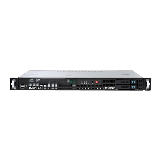
EP SERVER Dimensions EP SERVER For IPedge systems of up to 40 users. Dimensions • Height 2.362 in. (60 mm) 1.35U (Requires 2U rack space) • Width 9.25 in. (235 mm) Fits a standard 19 inch rackmount • Depth 8.12 in. 208.5 mm) •... -
Page 40: Ep Front Panel
RACKMOUNT INSTALLATION EP Front Panel EP Front Panel The IPedge EP servers has Two USB connectors, three LED indicators and the power switch. Power Button Power On/Off Button - This applies or removes system power. When the power is turned off using this button main power is shut off but standby power to the system remains on. - Page 41 EC SERVER RACKMOUNT EP Rear Panel Connections 1. Attach the inner rails to the sever. 2. Attach the outer rails to the front of the rack mount cabinet. 3. Install the server chassis by sliding the inner rails into the outer rails. Slide the chassis in until the front chassis brackets contact the outer rail bracket.
-
Page 42: Em Server Rack Mount
EM SERVER RACK MOUNT Rack Mount Kit Installation EM SERVER RACK The IPedge EM Server is 25.6 inches (650 mm) deep. The included MOUNT mounting rails are designed for installation in four-post racks and cabinets. CAUTION! The IPedge EC and EM servers must only be installed in an equipment rack using the mounting rails. -
Page 43: Installing The Outer Rails To The Rack
EM SERVER RACK MOUNT Installing the Outer Rails to the Rack 1. Place the inner rack extensions on the side of the chassis aligning the hooks of the chassis with the rail extension holes. Make sure the extension faces “outward” just like the pre-attached inner rail. Refer to Figure 2-9. -
Page 44: Installing The Chassis Into A Rack
EM SERVER RACK MOUNT Installing the Chassis into a Rack Figure 2-10 Outer Rail Assembly Installing the Chassis into 1. Confirm that chassis includes the inner rails (A) and rail extensions a Rack (B). Also, confirm that the outer rails (C) are installed on the rack. Refer to Figure 2-11 Figure 2-11 Four Post Rack Installation... -
Page 45: Bezel Installation
BEZEL INSTALLATION EC Server Bezel inserting). When the server has been pushed completely into the rack, you should hear the locking tabs “click”. Refer to Figure 2-12 4. (Optional) Insert and tighten the thumbscrews that hold the front of the server to the rack. Figure 2-12 Server Chassis Install BEZEL INSTALLATION The IPedge bezel is an option. -
Page 46: Em Server Bezel
EP SERVER CHASSIS INSTALLATION EM Server Bezel 1. After the chassis has been secured to the rack place a key into the slots on each end of the bezel. 2. Rotate the keys 90 degrees. 3. Place the bezel on the front of the chassis. 4. -
Page 47: Horizontal Mount
EP SERVER CHASSIS INSTALLATION Horizontal Mount Horizontal Mount Attach the rubber pads to the bottom of the chassis. Four pads are included with the server chassis. Vertical MOunt Attach the vertical mount base (two pieces) to the left side of the chassis, as viewed from the front. - Page 48 EP SERVER CHASSIS INSTALLATION Rack Mount Figure 2-15 Right side Rackmount Bracket 2. Attach the left side bracket with the three screws provided. 3. Place the power supply on the bracket and secure with the supplied cable tie as shown in and 2-16 Figure 2-16 Left Side Bracket with Power Supply 4.
-
Page 49: Rack Position
EP SERVER CHASSIS INSTALLATION Rack Position Rack Position The EP server requires 2U vertical space in the equipment rack. The server is 1.35 U high. The extra space must be left above the EP server chassis. Refer to Figure 2-5. 15.9 Other Equipment 15.9... -
Page 50: Power Requirements
IPedge server. The recommended UPS from ONEAC are shown in Table 2-3. The UPS shown in the table include power conditioning. If you already have a UPS in place Toshiba recommends that you install the power conditioner listed in Table 2-3. -
Page 51: Chapter 3 - Network Requirements
The following servers must be available to the IPedge server. DNS - The enterprise name assigned to the primary node must be registered with the DNS service. Toshiba recommends that the IPedge server name(s) be registered with the DNS. If equiped, the IPedge Meeting names must be registered with the DNS. -
Page 52: Voip Requirements Remote Users
LAN REQUIREMENTS VoIP Requirements Remote Users VoIP Requirements • Network Reliability – 99.99% Remote Users • Layer 3 voice prioritization recommended – Layer 3: DiffServ: Enabled / ToS Type:DSCP / DSCP for Voice: • 88kbps (G.711 audio) in each direction per simultaneous call –... -
Page 53: Voip Requirements Wifi Users
LAN REQUIREMENTS VoIP Requirements WiFi Users The IPedge communication system is an IP system. At each site all of the system components are connected via a LAN. The IPedge server, on-site IPTs, gateways, other servers communicate over the site LAN. Other devices connect over a WAN or the Internet. - Page 54 LAN REQUIREMENTS VoIP Requirements WiFi Users Figure 3-1 Enterprise Network witn Strata CIX System A Strata CIX system can be connected to an IPedge system via IPedge Net. When the databases, IPedge and CIX, are programmed correctly calls will be processed from one system to the next. This means that an IPedge system can be added to an existing CIX system.
-
Page 55: Broadcast Address
BROADCAST ADDRESS Calculation Example BROADCAST ADDRESS A broadcast address is used to indicate that the information being sent should be delivered to every client on the local area network. These addresses are always the highest number possible in a particular network address or subnet. - Page 56 BROADCAST ADDRESS Calculation Example 4. Note the value for the broadcast address calculated by the application. Installation Manual August, 2011...
-
Page 57: Chapter 4 - System Installation
Chapter 4 – System Installation PRE-INSTALLATION Refer to the IPedge Hardware chapter in this document for power, REQUIREMENTS environment, and UPS requirements. Refer to the LAN Requirements chapter for network performance specifications and measurement tools. Before starting this procedure the following information is required for each IPedge server. -
Page 58: Installation
INSTALLATION INSTALLATION This list is a summary of the installation steps for each server. The steps in detail follow. • Connect the IPedge server to a PC or network. – IPedge EC and EM servers - Connect the network cables to the eth0, eth1, and IPMI connectors before the server power is applied. -
Page 59: System Summary Information
NETWORK CONFIGURATION System Summary Information 5. Login to Enterprise Manager on the IPedge server using the default IP address, User ID and Password. System Summary 6. The System Summary information must be entered. The first screen Information shown after login is the System Summary. Click on the Edit icon. Enter the Enterprise Name and Address for this server. - Page 60 NETWORK CONFIGURATION System Summary Information 2. The Webmin information screen will appear. Advanced IPedge 3. On the Webmin page select Networking > Network Configuration then click on the Network Interfaces icon, select the Activated at Boot tab. 4. In the list of interfaces double-click bond0. 5.
-
Page 61: Set Default Gateway
NETWORK CONFIGURATION Set Default Gateway 6. Enter the IP address, Netmask, and Broadcast address. 192.168.254.250 255.255.255.0 192.168.254.xxx 7. Click to set MTU to Default. Note: The following steps must be completed as shown. Do not click on Save and Apply or Apply Configuration. If Webmin stops responding go to “If Webmin Stops Responding”... - Page 62 NETWORK CONFIGURATION If Webmin Stops Responding 18. Enter the IPedge server Hostname. The Hostname should be descriptive of the server such as the name of the city or location on a campus. Note:The Hostname should be the same as the server name. 19.
-
Page 63: Set System Time
6. In the Change timezone tab set the local time zone. 7. In the Time server sync tab enter the Timeserver hostname. Use an NTP pool. Toshiba recommends that the system sync to an NTP pool once each day. In the example below a local region NTP pool (north-... -
Page 64: Real Time Clock Hardware
NAME EACH SERVER Real Time Clock Hardware america.pool.ntp.org) has been assigned and the system is set to synchronize everyday at midnight. 8. Close the Webmin window. Real Time Clock Hardware The real time clock hardware can take up to eleven minutes to update after the System Time procedure, above, is finished. - Page 65 NAME EACH SERVER Real Time Clock Hardware 3. Click on the Edit icon. 192.168.254.250 Edit icon 4. Enter the new: Server Name - A unique descriptive name (same as the Host name for this server) and Community Name - (default is communityName) this name is use as authentication by some internal processes.
- Page 66 NAME EACH SERVER Real Time Clock Hardware 7. Select Administration > Enterprise > Servers. Click on the gray database synchronization icon to open the database sync page. 8. Check-mark the Table Name box to select all of the tables then, click on the synchronize database icon.
-
Page 67: License
Upload and Apply License LICENSE Licenses are purchased through the Toshiba FYI web site. After the licenses have been purchased download the license to the Administration PC. The file can be saved to any file storage unit on a network that the administration PC and the IPedge server can access. -
Page 68: Change Ftp Passwords
CHANGE FTP PASSWORDS Over Subscribing CHANGE FTP For added system security some of the system passwords must be PASSWORDS changed from the default settings. 1. Login to Enterprise Manager. 2. If this is a multi-node system select the server. 3. Select Application > Webmin. 4. -
Page 69: Media Server Channel Guide
2. Do not change the SysChannelBegin parameter, the default value is 3. The default value of the SysChannelTotal parameter is -1. Do not change this value unless directed by Toshiba Engineering. Media Server The Media Server channels must be allocated to: Configuration •... -
Page 70: Restart The Media Server
IPMI/BMC IP ADDRESS Restart the Media Server answers. RBT and ROT for SIP stations and SIP trunks after the destination answers. Use the following to set the initial Media Server Channel allocation. • Media Server Conferences = (the number of Media Server licenses)-(the number of stations in the largest paging group) then, divide by 2. -
Page 71: Meeting Conference
The IPMI connection must be able to route to the IPedge LAN connection. WARNING! This connection allows access to the Linux operating system of the IPedge server. Toshiba recommends that you change this user name and password. Record and safely store this information. If lost this password can not be recovered. - Page 72 MEETING INITIAL CONFIGURATION MEETING IP Address Change Procedure group Web Conference Server - The web conference server name. This is the name registered in the DNS server. 3. Ensure that the Stack IP Address and Gateway Address are set to the IPedge server IP Address.
-
Page 73: Https Certificate
HTTPS CERTIFICATE MEETING IP Address Change Procedure 6. Enter the IP Address of the IPedge server in the Circuit Group Address field. IPedge Server Addr IPedge Server Addr This is the end of the Meeting initial configuration. HTTPS CERTIFICATE If you are going to use https secure connection to the Enterprise Manager create the https certificate. -
Page 74: Assign Member Node
ASSIGN MEMBER NODE MEETING IP Address Change Procedure ASSIGN MEMBER NODE The previous procedure sets up each IPedge server as a stand alone system. The following procedure changes a server to a member server and attaches that server to the Primary Node. This procedure is performed for each member server in an enterprise. -
Page 75: Add Member Node
ADD MEMBER NODE MEETING IP Address Change Procedure 8. Repeat this process for each Member Node. ADD MEMBER NODE The following process adds then, attaches the member nodes to the primary node. IPedge EC and EM servers can be a primary node. 1. -
Page 76: System Security
SYSTEM SECURITY MEETING IP Address Change Procedure 4. The primary node will start the database synchronization process. This can take several seconds to a few minutes. The Database Status indicator will change to green when complete. Click on the Reload icon to refresh the status display. -
Page 77: Detach A Member Node
1. Toshiba recommends that you perform a full backup of the database on the server you are going to detach before starting this procedure. - Page 78 This page is intentionally left blank.
-
Page 79: Chapter 5 - Enterprise Manager
Chapter 5 – Enterprise Manager Enterprise Manager is a web browser based application that resides on every IPedge server. The Administration Terminal is a PC connected to the network, no special software is required. Enterprise Manager is a browser based interface that can be accessed from any computer with network access to the Primary node. -
Page 80: Roles
ROLES Create a New Role ROLES There are two types of Enterprise Manager user roles; • System Administrators • Telephone Users Each role is defined as a list of permission items (access rights) that determine the user’s access level in Enterprise Manager. The IPedge system has four technician roles and two telephone user roles defined when shipped. -
Page 81: Phone User
USERS Phone User Role Name - Select the name of the role that defines the permissions for this user. Email Address - This entry is required but not used at this time. 5. Click on the Save icon. Phone User To add phone user: 1. - Page 82 This page is intentionally left blank.
-
Page 83: Chapter 6 - Webmin
Chapter 6 – Webmin Webmin is a graphical user interface used to simplify Linux operating system management. Webmin lets you perform these tasks through a web interface, and automatically updates all of the required configuration files. Webmin is accessed through Enterprise Manager, select Application > Webmin. -
Page 84: Shutdown System
SHUTDOWN SYSTEM SHUTDOWN SYSTEM 1. Select Application > Webmin. 2. In the Webmin screen select System > Bootup and Shutdown. 3. Click on the Shutdown System button. Important! Do not change the start At boot flag for any service. Installation Manual August, 2011... -
Page 85: Chapter 7 - Ipedge System Backup
Chapter 7 – IPedge System Backup BACULA The IPedge system backup process is controlled by Bacula, a Client/ Server based backup program. Bacula is a set of programs that manage the backup, recovery, and verification of the IPedge configuration database for a stand alone system or every node on an enterprise network. -
Page 86: Backup Schedule
BACKUP SCHEDULE Change Backup Schedule BACKUP SCHEDULE When a system is installed the backup volume, which is the location of the backup files are defined in the default configuration. By default, the backup is run at 3:30 AM (0330 hours) local time. A full backup is performed every Tuesday. -
Page 87: Create A New Backup Schedule
BACKUP SCHEDULE Create a New Backup Schedule 6. The schedule detail window will open. The window below shows a schedule to run every month, on each Tuesday at 2:30 a.m. 7. Select the schedule you want then, click on the OK button. Create a New Backup Use the following procedure to create a new the IPedge backup schedule. -
Page 88: Verify Backup Job Status
RESTORE FROM BACKUP Verify Backup Job Status 8. Click on the ellipses button at the end of the line to set the schedule. 9. Select the schedule you want then, click on the Create button. Verify Backup Job Status 1. Navigate the Bacula main screen. 2. -
Page 89: Manual Backup
MANUAL BACKUP A backup can be run manually any time. Running a manual backup does not effect the automatic backup schedule. Toshiba recommends that you run a backup before making a critical change. The resulting manual backup file can be downloaded to the PC the system administrator is using. -
Page 90: Download Backup File
MANUAL RESTORE Download Backup File Download Backup File This process copies the backup file on the IPedge server to any location the PC the administrator is using can access. 1. Login to Enterprise Manager. Select Application > Webmin. 2. If this is a multi-node system select the Primary server. 3. -
Page 91: Restore The Server
MANUAL RESTORE Restore the Server Restore the Server This process restores the IPedge server. Note: The licenses for the server database that you are about to restore must be applied before you restore the database. 1. Login to Enterprise Manager. Select Application > Webmin. 2. - Page 92 This page is intentionally left blank.
-
Page 93: Chapter 8 - Https Configuration
Chapter 8 – HTTPS Configuration In HTTPS mode all communication between the Administrator’s browser and Enterprise Manager is carried over secure tunnel using SSL. • To setup HTTPS configuration in enterprise systems with more than one IPedge server the Primary Server must be configured first. •... -
Page 94: Root Certificate Download
TURN HTTPS OFF Root Certificate Download be terminated. Please wait several minutes for the web server to restart before logging back to the IPedge server. 6. After the restart, login to the server using the same URL. The web server will automatically redirect to the HTTPS login. For Example: http://serverName:8080/oamp will be redirected to https://serverName:8443/oamp, please observe the changes in bold... - Page 95 TURN HTTPS OFF Trust the Certificate URL when accessing Enterprise Manager. The default is: http:// serverName:8080/oamp. Installation Manual August, 2011...
- Page 96 This page is intentionally left blank.
-
Page 97: Chapter 9 - Ipt Software Update
Chapter 9 – IPT Software Update INTRODUCTION Toshiba IPT5000-series telephones can connect to IPedge servers. For the telephones to fully function with the IPedge features the telephone software must be updates to the latest version. The following procedure details the steps to update your existing IPT5000-series telephone software for connection to an IPedge server. - Page 98 IP Telephone Hardware Note: The latest software version will always be available on the Toshiba FYI web site. 6. Select the 4-line LCD and 9-line LCD software file locations. Use the Browse button to navigate to the files. Then, click on Upload.
- Page 99 INSTALLATION IP Telephone Hardware 10. The screen will show the update process status. NorthTower012 NorthTower012 NorthTower012 NorthTower012 NorthTower012 Update successful The indicators and control icons for the IP Phone software update process are shown below. Abort Updating Phones Then Stop Update Process Let Updating Phones Finish Then Stop Update Process Update Process Not Started...
- Page 100 This page is intentionally left blank.
-
Page 101: Chapter 10 - Network Address Translation
Chapter 10 – Network Address Translation Inside Outside IPedge Server Media Relay Server Public IP Address Public Network Private IP Address Router Ports Ports 21000 ~ 22999 21000 ~ 22999 MEDIA RELAY SERVER Enter the Public IP address of the IPedge server. Enter the port range to SETUP be used for calls. -
Page 102: Network Security
IPedge server are the responsibility of the installing dealer and/or customer and vary by the needs and level of protection determined by the customer’s IT department. Toshiba technical support does not assume responsibility to provide specific commands or to verify a network or specific IPedge server is secure. -
Page 103: Cisco
FIREWALL SETUP Cisco Cisco 1. Verify that the Cisco firewall software is up to date. 2. Add the TCP and UDP ports to the Manage Ports list. Add the following ports: • 1100 to 1105 TCP (Systems connecting with unifier) •... - Page 104 FIREWALL SETUP Cisco 3. In Configuration > Enable Traffic Through ... > Translation Rules. Select Use NAT the, enter the Inside (IPedge private) Address and the Outside (IPedge public) Address. IPedge Private IP Address IPedge Public IP Address 10-4 Installation Manual August, 2011...
- Page 105 FIREWALL SETUP Cisco 4. In the Edit Access Rule dialog Select permit as the action, enter the IPedge private IP address as the Destination Host/Network. Under Protocol and Service select TCP. Click on OK. IPedge Private Addr Private Addr Installation Manual August, 2011 10-5...
- Page 106 FIREWALL SETUP Cisco 5. In the Edit Access Rule dialog Select permit as the action, enter the IPedge private IP address as the Destination Host/Network. Under Protocol and Service select UDP. Click on OK. IPedge Private Addr Private Addr 10-6 Installation Manual August, 2011...
-
Page 107: Sonicwall Setup
SONICWALL SETUP SONICWALL SETUP 1. Login to the SonicWALL firewall. 2. In the menu along the left side of the screen select Network > Address Objective. Add the name of the IPedge server and the IP address of the IPedge server. 192.168.254.250 3. - Page 108 SONICWALL SETUP 4. Ports 1718 ~ 1719 UDP (Remote IP Telephones set registration) 5. MRS (Media Relay Server) RTP 21000 ~ 22999 UDP (Remote IPT or SIP phone audio) 10-8 Installation Manual August, 2011...
- Page 109 SONICWALL SETUP 6. SIP: 5060 UDP (SIP trunks or remote SIP phones) 7. When using Unifier add a service: 1100 to 1105 TCP (Only use for systems connecting with unifier. Example Network ACD/CM to a CIX or IPedge that is outside the firewall) 8.
- Page 110 SONICWALL SETUP Check-mark the Enable NAT Policy and Create a reflexive policy boxes. 10. Select Firewall > Access Rules. Click on WAN to LAN. Click on Add Service. 10-10 Installation Manual August, 2011...
-
Page 111: Nat/Firewall Settings
SONICWALL SETUP NAT/Firewall Settings: 11. Select the group you created above in the Service field. Ensure that the Allow radio button is selected. Click on OK. NAT/Firewall Settings: 1. When using a Sonicwall SIP Transformations will need to be enabled. Select VoIP->Settings. - Page 112 SONICWALL SETUP NAT/Firewall Settings: 2. Check mark Enable consistent NAT. 3. Check mark Enable SIP Transformations. 4. Check mark Premit non SIP packets on signaling port. 5. Ensure that no other check-boxes on this screen are checked. 10-12 Installation Manual August, 2011...
-
Page 113: Chapter 11 - Sip Trunk Configuration
However, unlike a traditional T1 circuit, a SIP trunk enabled circuit does not have to be physically provisioned and divided to separate the voice channels from the data channels. REQUIREMENTS • Contact the Toshiba Sales Applications Desk for the latest SIP Trunk Service provider list. • License: I-CP-TRUNK Installation Manual... -
Page 114: Capacities
CAPACITIES CAPACITIES The IPedge system can support up to 1000 URI entries. Refer to Table 11-1. Table 11-1 Trunk Capacities Trunks EC Server EM Server IPedge Net IP channels SIP Trunk channels Total Analog, T1, and ISDN trunk channels connected by gateways. -
Page 115: Sip Trunk Example
SIP TRUNK EXAMPLE SIP TRUNK EXAMPLE The example shown below is a general system plan. Refer to the specific provider sections of this document. Third Party Networks PSTN SIP Provider Media Gateway Network Softswitch Internet Access Customer Premise There are many ways to set up a public IP address for the IPedge system. -
Page 116: Sip Trunk Group Programming
The additional digits will be ignored. All of the received digits must be in the URI table. Note: Toshiba recommends that you enable Intercept and program destination in Trunk > DID Intercept. Programming the In the Outgoing tab set the parameters for outgoing calls on this trunk Outgoing Line Group group. -
Page 117: Olg Flexible Access Code Programming
OLG FLEXIBLE ACCESS CODE PROGRAMMING Creating the Channel Group 10. Leave the remaining parameters blank. 11. Click on the Save icon. Note: Notice that Incoming and Outgoing trunk group with the same Trunk Group Number have been created. OLG FLEXIBLE ACCESS An access code is required for the OLG that was setup for the SIP CODE PROGRAMMING Trunks. -
Page 118: Service Assignment
OLG FLEXIBLE ACCESS CODE PROGRAMMING Service Assignment 6. Click on the Save icon. Note: If your SIP trunk provider does not support NAT and does not perform any SIP fix up for NAT'd addresses, set Connection to Media Relay Server to Manual in the SIP Trunk service definition. Service Assignment 1. -
Page 119: Sip Trunk Configuration Patterns
SIP TRUNK CONFIGURATION PATTERNS Service URI SIP TRUNK The following tables show the typical SIP trunk configuration patterns. CONFIGURATION The tables show the data entered in to the IPedge database using PATTERNS Enterprise Manager. Pattern A Registered With or Without Authentication Parameter Entry Trunk >... - Page 120 SIP TRUNK CONFIGURATION PATTERNS Service URI Pattern B No Registration and No Authentication Parameter Entry Trunk > SIP Trunking > Service Definition Registration Mode None Domain Name SIP Provider IP address or domain name SIP Server Use an OutBound proxy if the SIP Provider requires Primary Voice Packet Configuration Primary Audio Codec...
- Page 121 SIP TRUNK CONFIGURATION PATTERNS Service URI Registration with or without Authentication and Pattern C Port may be different then 5060 or no SRV records Parameter Entry Trunk > SIP Trunking > Service Definition Registration Mode Client Domain Name IP or domain name SIP Server IP or domain name: 5060 (Your SIP provider may use a differen port)
- Page 122 SIP TRUNK CONFIGURATION PATTERNS Service URI Pattern D No Reg No Authentication and Port may be different then 5060 or no SRV records Parameter Entry Trunk > SIP Trunking > Service Definition Registration Mode None Domain Name IP or domain name SIP Server IP or domain name: 5060 (Your SIP provider may use a differen port)
- Page 123 SIP TRUNK CONFIGURATION PATTERNS Service URI Pattern E - No Registration With Authentication On Parameter Entry Trunk > SIP Trunking > Service Definition Registration Mode None Domain Name SIP Provider IP address or domain name SIP Server Use an OutBound proxy if the SIP Provider requires Primary Voice Packet Configuration Primary Audio Codec...
- Page 124 SIP TRUNK CONFIGURATION PATTERNS Service URI Other Different Than Patterns A ~ F Parameter Entry Trunk > SIP Trunking > Service Definition Registration Mode Domain Name SIP Server Primary Voice Packet Configuration Primary Audio Codec Secondary Voice Packet Configuration Secondary Audio Codec Consult with your SIP Trunk provider.
-
Page 125: Chapter 12 - Gateways
Chapter 12 – Gateways INTRODUCTION The IPedge is an all IP telephony system. To interface with analog telephones or analog CO trunks a gateway is required. The following steps apply to the Audicodes MP118 but the general process applies to other gateways. -
Page 126: Audiocodes Mp118 Fxo
AUDIOCODES MP118 FXO AUDIOCODES MP118 FXO This section is for setting up an AudioCodes MP118 as an FXO gateway. To setup FXS operation refer to “AUDIOCODES MP118 FXS” on page Chapter 12 –-10 This is for MP118 release 5.8 or later. The AudioCodes MP118 defaults: •... -
Page 127: Set Network Time
UPGRADE SOFTWARE Set Network Time 5. Click on submit. 6. Click on the Burn icon at the top of the screen to save the settings. 7. Log in using the new IP address. Set Network Time Set the Network Time Protocol server addaress. 1. -
Page 128: Download Ini File
File Download 4. In the load cmp file dialog box click on the Browse button. Navigate to the INI file loaded from the Toshiba FYI web site. Ensure that the following files are in the folder with the INI file. - Page 129 MP118 MEDIA SETTINGS Load INI file to the Gateway Coders 12. Select Protocol Configuration > Protocol Definition > Coders 13. Ensure the following: Coder Name G.711 mu-law Packetization Time = 20 Rate = 64 Silence Suppression = Disabled Coder Name G.729 Packetization Time = 20 Rate = 8 Silence Suppression = Disabled...
- Page 130 MP118 MEDIA SETTINGS Load INI file to the Gateway 21. Select Protocol Configuration > Routing Tables > Tel To IP Routing. Set the following: Src Trunk Group = * Dest Phone Prefix = * Source phone Prefix = * Dest IP Address = IP address of the IPedge system IPedge IP address 22.
-
Page 131: Endpoint Numbers
MP118 MEDIA SETTINGS Endpoint Numbers Enter the Destination Number for Port 5 FXO. Refer to the URI table in the IPedge database. A value from the URI table 4001 for example Note: Start the Destination Phone Number entries with the first FXO port. -
Page 132: Ipedge Configuration
IPedge CONFIGURATION Endpoint Numbers IPedge CONFIGURATION The next steps program the IPedge SIP trunk group to route the calls received through the gateway. Login to Enterprise Manager for the following. Set Up Trunk ILG 1. Select Trunk > Trunk Groups then, click on the New icon. 2. - Page 133 IPedge CONFIGURATION Endpoint Numbers 5. Select Trunk > SIP Trunking then, click on the Service Assignments tab. Set: SIP Channel Group = the TGN of the SIP Trunk Group (should already be set). Service Definition Index = 1 for the first SIP trunk group, each for additional SIP Trunk group increment the Index number (2, 3, etc.) 6.
-
Page 134: Audiocodes Mp118 Fxs
AUDIOCODES MP118 FXS Setup IP Address AUDIOCODES MP118 FXS This section of the document covers the AudioCodes MP118 setup as an FXS gateway. Setup IP Address Refer to “SET IP ADDRESS” page Chapter 12 –-2 to set the MP118 and to connect to the administration interface. Setup NTP Service Refer to “Set Network Time”... - Page 135 AUDIOCODES MP118 FXS FXS Setup 9. Select Protocol Configuration > Sip Advanced Parameters >advanced Parameters. Set the Disconnect on broken connection = No Set Enable current disconnect = Enabled. 10. Click on the Submit button. 11. Select Protocol Configuration > Routing Tables > Routing General Parameters.
-
Page 136: Ipedge Configuration For Fxs
IPedge CONFIGURATION for FXS Verify Station Registration Assign the next analog DN channel 2. Next to channel 3, and so on. 19. Click on the Submit button. 20. Select Protocol Configuration > Hunt Groups > Hunt Group Settings. Hunt Group ID = 2 Channel select mode = By Dest. -
Page 137: Audiocodes Mediant1000 Pri
Set IP Address in single IP settings Upgrade software to Select Management > Software Update > Software Upgrade Wizard 5.8.xxxx 1. Click on Start Software Upgrade. 2. Select 5.8 CMP file. Click on Next. 3. Select the Toshiba provided INI file. Installation Manual August, 2011 12-13... -
Page 138: Mediant1000 Configuration
6. Browse to file location, then click Send File. 7. Click on Next. 8. Browse to the TOSHIBA ini file, then click send file 9. Click on Next. 10. Browse to the T1 Winkstart CAS file ini file, then click send file 11. -
Page 139: Trunk Protocol And Configuration
MEDIANT1000 CONFIGURATION Trunk Protocol and Configuration 4. Click on the Apply Trunk Setting button. A screen alert may pop up to inform you must reboot/Reset. Ignore the the message. 5. Click on the BURN icon. A green light may appear on the screen or T1 port after reset to indicate that Layer 1 and Layer 2 are up. -
Page 140: Ipedge Configuration
IPedge CONFIGURATION Trunk Protocol and Configuration 10. Select Protocol Configuration > Routing Tables > Tel To Ip Routing Src Trunk Group = * Dest Phone Prefix = * Source phone Prefix = * Dest IP Address = 192.168.254.254 (IP address of the IPedge server) 11. - Page 141 IPedge CONFIGURATION Trunk Protocol and Configuration For more detail about IPedge data refer to “IPedge CONFIGURATION” on page Chapter 12 –-8. For detailed SIP trunk configuration information refer to Chapter –SIP Trunk Configuration. Installation Manual August, 2011 12-17...
-
Page 142: Audiocodes Mediant1000 T1
AUDIOCODES MEDIANT1000 T1 Trunk Protocol and Configuration AUDIOCODES This section is for setting up an AudioCodes Mediant 1000 as a T1 MEDIANT1000 T1 gateway. Refer to “BASIC CONFIGURATION” on page Chapter 12 –-13 for the administrative and software version setup. MEDIANT 1000 1. -
Page 143: Ipedge Configuration
MEDIANT 1000 CONFIGURATION IPedge Configuration 14. Select PROTOCOL CONFIGURATION > ROUTING TABLES > ROUTING GENERAL PARAMETERS Enable alternate routing = Disabled 15. Select PROTOCOL CONFIGURATION > ROUTING TABLES > TEL TO IP ROUTING Src Trunk Group = * Dest Phone Prefix = * Source phone Prefix = * Dest IP Address = 192.168.254.254 (IP address of the IPedge server) 16. - Page 144 This page is intentionally left blank.
-
Page 145: Chapter 13 - Meeting
Chapter 13 – Meeting IPedge MEETING INITIAL The IPedge Meeing server, installed on the IPedge EC and EM server CONFIGURATION platforms, requires a license to operate. Use this procedure to configure the Meeting server to run in your system environment. Meeting IP Address and 1. - Page 146 IPedge MEETING INITIAL CONFIGURATION Meeting IP Address and Hostname The entries will be in this format: admin.domainname.domaintype. For example: admin.yourcompanydomain.com IPedge server IP address admin.domain_name.com webconf.domain_name.com IPedge Server Host Name Note: The admin and webconf host addresses must be entered in the order shown.
- Page 147 IPedge MEETING INITIAL CONFIGURATION Meeting IP Address and Hostname Meeting Server Name admin.domain_name.com 949-583-3000 webconf.domain_name.com IPedge server IP address 6060 IPedge server IP address 7. Click on the Submit button. 8. Under System Configuration, select the Circuit Groups tab. IPedge server IP address 9.
- Page 148 IPedge MEETING INITIAL CONFIGURATION Meeting IP Address and Hostname 11. Enter the IPedge SIP station DNs to be used by the Meeting service. Assign the same number of stations as there are Meeting licenses assigned. The stations should all be in a circular hunt group. IPedge server IP address IPedge server IP address 12.
-
Page 149: Chapter 14 - Net Server
Chapter 14 – Net Server Net Server is pre-installed on the IPedge system and can be activated using IPedge Enterprise Manager. Add Net Server to Enterprise Manager and configure the IO port in the IPedge system. After applying the license, Net Server is ready to be used. -
Page 150: Setup The I/O Port
SETUP THE I/O PORT 5. Select Net Server from the Application Name list (shown below). 6. Add the IP Address: 127.0.0.1 7. Click OK. SETUP THE I/O PORT 1. Using Enterprise Manager, go to System > I/O Device. 2. Click the New icon. 3. -
Page 151: Status
NET SERVER MENU Status Status The Status sub menu provides real time information on the Net Server. Clients Tab Clients tab shows the status of all the client applications that are connected to the Net Server. It includes all the component applications that are parts of Net Server and all the client Call Manager applications that are connected to the Net Server. -
Page 152: Setup
NET SERVER MENU Setup Setup Setup sub menu allows the administrator to manage client users, service components, applications, and groups. Users tab is used to manage the login information of the client applications. Clients can be automatically added (see Net Server Property menu) or can be added/modified from this tab. - Page 153 NET SERVER MENU Setup When you Add or Edit a checked entry, data can be entered from the following screen. Name Description User Name Name of the user to use for Net Server login Password Password used for Net Server login Extension Directory Number (DN) of extension that the user controls Service Access...
- Page 154 NET SERVER MENU Setup Services Tab Use the Services tab to manage the component services running under Net Server. It defines which services are on the server and what clients can use them. Services are automatically defined when they are installed, and do not need to be modified.
- Page 155 NET SERVER MENU Setup Field Description Name Service name which must be unique in the system Password Password for the service to login to Net Server. Typically, it should not be changed. Description Description of the service Service Level Service Level determines which clients can access this service. Each client has a service level access number, and a client will have access to all services whose Service Level is less than or equal to the client’s service level access number.
- Page 156 NET SERVER MENU Setup Application Tab The Application tab defines the users for each application and allows you to assign a policy based on the user or the group. Please see Group tab section for the specific information on the group policies. See the “Server Based Call Manager Configuration”...
- Page 157 NET SERVER MENU Setup Field Description Application Name Name of the application User or Group Usually, the client name of the user is shown (see Clients). When it is set to <Default> (or leaving it blank) the settings for the Default User can be defined.
- Page 158 NET SERVER MENU Setup Field Description Group Admin Privilege#1/2 Determines if this user can perform functions for the group (unique to each application). (value: 4/8) Other App Privilege#1/2 Determines if this user can perform other functions (unique to each application). (value: 16/32) User Groups Tab User Groups tab defines the group of users to apply the common settings to multiple users.
- Page 159 NET SERVER MENU Setup Field Description Group Name Name of the group Users in Group List of users that are currently included in the group. A user can be removed from the group by selecting the user and clicking Remove. Other users List of users that are not currently in the group.
- Page 160 NET SERVER MENU Setup Properties Tab Properties tab is used to configure the Net Server. Item Description Allow Net Server to Check this to automatically add users when they connect to the Net automatically add new Server first time. It is primarily intended to allow Call Manager users to clients (Note: On local port create a user name and password in the system when they login the first only)
-
Page 161: Level 2 Menu
LEVEL 2 MENU Devices Menu LEVEL 2 MENU Level2 menu allows the administrator to configure various items managed by Level2 which processes the Computer Telephony Integration with the IPedge system. Devices Menu Device menu manages the device table which provides an Extension Directory for Call Manager. - Page 162 LEVEL 2 MENU Devices Menu Canned Presence Canned Presence (Message) menu enables the administrator to define (Message) messages used by Call manager for the additional information on the presence status. System standard default messages are defined, and the administrator can change them. Twenty different messages are possible. 14-14 Installation Manual August, 2011...
-
Page 163: Logging
Logging Logging menu can control the level of trace information for the problem investigation. All items are checked by default and do not have to be changed unless instructed to so by Toshiba Technical Support. Installation Manual August, 2011 14-15... -
Page 164: Dial Rule Menu
Dial Rule Menu Dial Plan Dial Rule Menu Dial Rule Menu allows the administrator to define the dialing rule to be applied automatically when the application such as Call Manager makes a call. Dial Plan Dial Plan sub menu defines how the system interprets the dialing string. When the Use SERVER Dial Plan is checked in the Preference in Call Manager, dialing digits from Call Manager are interpreted based on the rule defined in the Dial Plan. -
Page 165: Calling Within My Home Area Code
Dial Rule Menu Calling Within My Home Area Code Calling Within My Home • Home Area Code – Set this to the Area code where the phone is Area Code located. This will be used by Call Manager to determine which dialed calls are within your home area code and when searching a contact manager (reverse screen-pop) the dialed number will need the area code included, i.e. -
Page 166: Calling Outside The Home Area Code
Dial Rule Menu Calling Outside the Home Area Code • Add+1 – Check the box if you need to dial a leading 1 before the number for calls within your Home Area Code. • Dial Area Code Plus the Number – Check the box when the home area code is also to be dialed. -
Page 167: Server Based Call Manager Configuration
Server Based Call Manager Configuration Create User Groups • For Long Distance Calls add +1 – Check the box when you need to have a leading one (1) added when making long distance calls outside your home area code. • Click Save when done. -
Page 168: Assign Users To Call Manager Application
Server Based Call Manager Configuration Assign Users to Call Manager Application Assign Users to Call By assigning Groups to the Call manager application enables you to Manager Application assign a common “Class of Service” and “Configurations” for all users in a group. - Page 169 Server Based Call Manager Configuration Assign Users to Call Manager Application 14. Repeat the preceding steps to add any remaining Call Manager user groups. 15. Default in User or Group can be used to setup the default settings for all users that are not included in any group or individual. 16.
-
Page 170: Assign Users To User Groups
Server Based Call Manager Configuration Assign Users to User Groups Assign Users to User Use this procedure to Assign Users as Call Manager Administrators . Groups 1. Use Net Server menu > Setup, then Users tab. 2. Check the user who needs to be a Call Manager administrator and click Edit icon. - Page 171 Server Based Call Manager Configuration Assign Users to User Groups To assign Users as Call Manager Users 1. Check the user who is a Call Manager user and click Edit icon. 2. Place a checkmark in the User group only as is shown in the following screen: 3.
- Page 172 Server Based Call Manager Configuration Assign Users to User Groups Create Configuration Files 1. Restart the Administrator’s Call manager if it is running using Admin Call Manager 2. Set up the buttons, Call Handler rules, skins, etc. as you would like the users’...
- Page 173 Server Based Call Manager Configuration Assign Users to User Groups Installation Manual August, 2011 14-25...
-
Page 174: Server Based Call Manager Upgrade
Installation The Call Manager upgrade software is provided as an rpm file from Toshiba FYI, and it needs to be stored in the PC that can connect to IPedge through Webmin from Enterprise Manager. From the PC, launch Enterprise Manager and run Webmin. In the Webmin, select Software Packages menu under System menu. - Page 175 Server Based Call Manager Upgrade Installation After clicking install, the following progress bar is shown to indicate the progress of the file upload to the server. When the upload is completed, the following screen displays. Please use the default value for all the settings. Click Install to start installing the Call Manager software upgrade to the server.
-
Page 176: Net Server Configuration
Server Based Call Manager Upgrade Net Server configuration Net Server configuration After the upgrade software is installed on the server, the administrator can choose whether to enable or disable the Server Based Call Manager upgrade. In the Net Server admin screen, select Properties menu from Net Server tab. -
Page 177: Chapter 15 - Messaging
Chapter 15 – Messaging Messaging is pre installed on the IPedge system and can be activated using IPedge Enterprise Manager. Once the Messaging license is activated, add the Messaging application to Enterprise Manager and then Messaging, then configure the application using the Application menu in Enterprise Manager. -
Page 178: Setup The I/O Ports
SETUP THE I/O PORTS SETUP THE I/O PORTS 1. From the System menu, select I/O Device. 2. Click the New icon. 3. Configure the I/O SMDI#0 for the Logical Device No. 4. Set the Application Type to Client 5. The Client IP address is 127.0.0.1 6. -
Page 179: Assign The Voicemail Sip Stations
ASSIGN THE VOICEMAIL SIP STATIONS ASSIGN THE VOICEMAIL 1. From the Station menu, select Station Assignment. SIP STATIONS 2. Click the New icon. 3. Enter the Prime DN that matches the appropriate numbering plan. 4. The Type should be SIP VM 5. -
Page 180: Add Stations To A Station/Hunt Group
ADD STATIONS TO A STATION/HUNT GROUP ADD STATIONS TO A 1. Using Enterprise Manager, add the voicemail ports to the Hunt STATION/HUNT GROUP Groups by going to Station > Station Groups. 3090 Make the following selections: Hunt is Distributed Hunt Pilot Number should be the one used in the Numbering scheme Example: When the Message button is pressed, it dials 3090. -
Page 181: Program Messaging
PROGRAM MESSAGING PROGRAM MESSAGING 1. Using Enterprise Manager, click Application > Messaging. 2. Select the appropriate system where Messaging resides. 3. Click OK. 4. From the main menu, click Registry > Parameters. 5. Check Default IPedge. 6. Assign Default PBX as 127.0.0.1 7. -
Page 182: To Restart Messaging
To Restart Messaging 16. Click on System > Channel Definition. Depending on the port licenses may or may not be populated. Received calls should be set to Yes. Beyond eight ports, the received calls display as No. Change them all to Yes. 17. - Page 183 To Restart Messaging 5. Scroll down and click the Restart button. The Restart status screen displays (shown below). Installation Manual August, 2011 15-7...
-
Page 184: Disk Full Notification
DISK FULL NOTIFICATION DISK FULL NOTIFICATION Under some conditions the server disk can become full. Use the following procedure to setup an email alert to the system administrator when the disk is 80% full. 1. Using Enterprise Manager, select Applications > Messaging. In the Messaging administration screen select Registry >... - Page 185 Chapter 16 – Maintenance INTRODUCTION The Toshiba IPedge system is an all IP telephone system running on an IP network. When troubleshooting consider that problems may be with the network as well as with the server. Use the following as a check list to help identify voice quality problems.
- Page 186 This process will login in to the server remote terminal. Change the User Name and Password for better system security. Record the User Name and Password. There is no password recovery process. Use this terminal only under the direction of a Toshiba engineer. 16-2 Installation Manual August, 2011...
-
Page 187: Alarm Notification
ALARM NOTIFICATION Temperature Failure ALARM NOTIFICATION The IPedge server can generate SNMP messages in response to specified alarm conditions. • Server Component stopping automatically • Server Component stopped manually • Server Component restart • Server chassis fan failure (Low fan speed) (EC and EM servers only) •... -
Page 188: Hardware Monitoring
BMC processor on the IPMI card in the IPedge server. This should be done only on the advice of a Toshiba engineer. The BMC takes a few minutes to reset. While the reset is processed there is no monitoring by the BMC. -
Page 189: Ipedge Recovery Disk
IPedge RECOVERY DISK Remote Console Function IPedge RECOVERY DISK The following procedure details the server recovery using the IPedge EC and EM server Recovery Disk. For EP servers refer to “EP SERVER RESTORE” on page Chapter 16 –-8. Important! Before starting the recovery process ensure that the LAN cable is connected to the eth0 connector and a LAN cable is connected to the IPMI port. - Page 190 IPedge RECOVERY DISK Recovery Procedure 9. When the BIOS Setup Utility screen use the cursor control keys to select Advanced > IPMI and press the Enter key. 10. Use the cursor control keys to highlight OS Boot Watch Dog then, press the Enter key.
- Page 191 IPedge RECOVERY DISK Recovery Procedure 16. When the Enterprise Linux screen (shown below) appears press the Enter key. 17. The system will format the hard disk and install the server software. This can take approximately 25 ~ 30 minutes. 18. When the installation is finished a screen will appear telling you that the installation is complete the Reboot button on the lower right corner of the screen will be enabled.
-
Page 192: Restore Database
EP SERVER RESTORE Restore Database 26. Verify that the OS boot Watchdog Timer is Disabled. If it is disabled go to Step 28. If it is Enabled, Highlight Disabled then, press the Enter key. 27. Highlight Yes then, press the Enter 28. -
Page 193: Recovery From Usb Flash Drive
4 again. 5. Remove the USB flash drive. 6. Download IPedge EP server ISO image file and zip file from Toshiba’s FYI website to the adminisrator PC. 7. Insert the USB flash drive into the administrator PC. -
Page 194: Ec Server Fan Replacement
4. Unplug the fan cable from the server board and remove the failed fan from the chassis. 5. Replace the failed fan with an identical fan available from Toshiba. 6. Replace the top chassis cover. 7. Plug in the power cord then set the rear panel power switch to ON. -
Page 195: Em Server Fan Replacement
5. Replace the failed fan with an identical 4-cm, 12-volt fan available from Toshiba. 6. Push the new fan into the vacant space in the housing while making sure the arrows on the top of the fan (indicating air direction) point in the same direction as the arrows on the other fans. -
Page 196: Power Up Server
Replace the power supply module with the same model, which can be ordered from Toshiba. 1. The failed power supply led will change from green to amber. First unplug the power cord from the failed power supply module. -
Page 197: Em Server Disk Drive Replacement
EM SERVER DISK DRIVE REPLACEMENT Power UP Server Figure 16-2 EM Server Power Supply Module Replacement EM SERVER DISK DRIVE The IPedge EM server ships with two Hard Disk Drives (HDD) in a RAID 1 REPLACEMENT configuration. In the event of a HDD failure the failed drive can be replaced without data loss or server down-time. - Page 198 EM SERVER DISK DRIVE REPLACEMENT Power UP Server 5. Click on the Display tab. Check the Target on ID number. If the Target on ID is #5, the HDD in Slot 0 should be replaced. If the Target on ID is #8, the HDD in Slot 1 should be replaced. Important! If both Target on ID #5 and #8 were displayed, please call Tech-Support.
-
Page 199: Dvd-Rom Drive Installation
DVD-ROM DRIVE INSTALLATION Remove Server Power 6. To remove the indicated HDD press on the red latch then carefully swing the arm open, as indicated below. Push the red button then, swing the arm open. 7. Pull the HDD straight out of the carrier. 8. -
Page 200: Remove Chassis Cover
DVD-ROM DRIVE INSTALLATION Remove Chassis Cover Remove Chassis Cover 1. Grasp the two handles on either side and pull the unit straight out of the rack until it locks (you will hear a “click”). 2. Depress the two buttons on the top of the chassis to release the top cover and at the same time, push the cover to the rear of the cabinet until it stops. -
Page 201: Program Update
The update files must be loaded into an update folder on the USD drive. Update File Source The update file can be downloaded from the Toshiba FYI web site or the Toshiba TSD Technical Support web site. The update files are TGZ format. -
Page 202: Remote Update Procedure
1. In Enterprise Manager select Maintenance > System Maintenance > Program Update. 2. In the Select Target Server screen click to check-mark the server you will up date then click on the Next button. • Select the update mode. Local Update - The update file is on a USB drive connected to the IPedge server. -
Page 203: Program Rollback
PROGRAM ROLLBACK Update File Source update file can be accessed from a USB drive connected to the IPedge server. 1. In Enterprise Manager select Maintenance > System Maintenance > Program Update. 2. In the Select Target Server screen click to check-mark the server you will up date then click on the Next button. -
Page 204: System Reboot
This feature supports DESI Telephone Labels, Inc. products only and requires DESI Print Engine 2.74 software or later and Toshiba format Keystrip paper. DESI keystrip paper is available for all Toshiba IP5000-series telephones DSS consoles and Add-On-Modules. To order DESI Software and Keystrip paper for Toshiba telephone products go to www.DESI.com or call 1-800-814-3922. - Page 205 THIS IS THE END OF THE DOCUMENT.