Table of Contents
Advertisement
Advertisement
Table of Contents

Related Manuals for Commend SIP Series P


Summary of Contents for Commend SIP Series P
- Page 1 PRODUCT MANUAL ENGLISH Commend SIP Series VERSION 2.0/0612...
- Page 2 Commend SIP Series Manufacturer’s Reference: This equipment fulfils the requirements of the EU standard 89/336/EEC (EN 55022, EN 55024). Therefore this equipment is CE-labelled. Please keep this description in safe custody! Attention: Mounting and installation of the SIP devices and of the equipment may be carried out by authorised ser- vice personnel only.
-
Page 3: Table Of Contents
Display Menu WS 800V / WS 800F SIP Series V, SIP Series VE Call Initiation at SIP-WS 500F SIP Series M Technical Support Connection SIP Series P, SIP Series V, SIP Series VE, SIP Series F SIP Series M Vers. 2.0/0612... -
Page 4: Introduction
Introduction Commend SIP Series Introduction Commend Security for the World of SIP SIP Stations with Intercom Power The full duplex capable stations of the SIP Series links the world of SIP technology with the reliability and quality of solutions by Commend, The stations are connected directly to the Ethernet (LAN/WAN) and in this manner are connected to a compatible SIP Server via the IP-network. - Page 5 Commend SIP Series Introduction SIP S – ACCORDING TANDARD HOW DOES IT WORK Each VoIP subscriber is registered automatically with the respective IP address at a server of the corre- sponding SIP provider. This provider assigns a new address to the subscriber according to the rules of the SIP standards, in form of “sip:01234567@providername.com”.
-
Page 6: Technical Data
PoE (Power over Ethernet): Standard IEEE 802.3af Power consumption of the terminal device: Class 0 (0.44 W to 12.95 W) SIP Series P, SIP Series V, SIP Series VE only: Power supply: 24 VDC ± 2 V, 500 mA or PoE... - Page 7 Commend SIP Series Introduction SIP Series P, SIP Series V, SIP Series VE, SIP Series F only: Operating temperature range: –20° C to +60° C (–4° F to 140° F) Storage temperature range: –20° C to +60° C (–4° F to 140° F)
- Page 8 Introduction Commend SIP Series SIP Series V, SIP Series VE: IP rating: IP 65 Mechanical impact resistance acc. EN 62262 SIP Series V: IK 09 SIP Series VE: IK 08 SIP-WS 800V: IK 07 Front panel: Stainless steel, 3 mm (0.12 in)
-
Page 9: Extent Of Supply
Commend SIP Series Introduction Extent of Supply SIP Series ”SIP Series P” ”SIP Series V” ”SIP Series VE” ”SIP Series M” ”SIP Series F” SIP station SIP station SIP module SIP station Screws for mounting ... -
Page 10: System Requirements / Compatibility
G8-VOIPSERV (for additional features) incl. Asterisk Server Compatibility SIP PBX Basically the SIP modules can be used with any SIP server. The following server types have been tested explicitly by Commend and therefore a proper functionality can be confirmed: Manufacturer* Type... - Page 11 Commend SIP Series Introduction SIP Series P SIP-WS 20xP SIP station with up to 3 programmable direct dialling buttons (white backlight) in polycarbonate construction for interior and outdoor areas. Each button can be allocated to a call number and the relevant label area can be filled in individually.
- Page 12 Introduction Commend SIP Series SIP-WS 201V: SIP-WS 202V: SIP-WS 203V: SIP-WS 800V: (1 direct dialling button) (2 direct dialling buttons) (3 direct dialling buttons) (keypad, display) SIP Series VE Vandal resistant SIP emergency stations with up to 2 programmable direct dialling buttons, stainless steel front panels with 3 mm (0.21 in) thickness, poke protection and special screws.
- Page 13 Commend SIP Series Introduction SIP-WS 800F MD: SIP-WS 500F: SIP-WS 800F: (with LCD-Display) (without LCD-Display) (with LCD-Display) SIP Series M SIP modules for integration in existing housings and panels or building of customer specific stations. Available in 2 different versions: with RJ 45 sockets mounted horizontally or vertically.
-
Page 14: Mounting
SIP Series P, SIP Series F For installation additional mounting material is required (must be ordered separately). Following additional mounting material is available for the SIP Series P, SIP Series F: Flush mount kit WSFB 50P Surface mount kit WSSH 50P The mounting instruction is split into following sections: ... - Page 15 Commend SIP Series Mounting Measurements Flush Mount Kit WSFB 50P Measurements in mm (inch), not to scale! *Mounting distance between flush ..Mounting frame mount boxes 150 (5.91) 135.6 (5.34) 30 (1.18)* front flush with plaster (0.59) 1 (0.04) 82 (3.23) (0.02)
- Page 16 Mounting Commend SIP Series Mounting Flush Mount Kit WSFB 50P To corresponding expansion opening of flush mount box of e.g. WS expansion module gasket MOUNTING DIRECTION gasket Illustration front panel ..Connection spacer (with gaskets) for connecting two flush mount boxes and...
- Page 17 Commend SIP Series Mounting Measurements Surface Mount Kit WSSH 50P Measurements in mm (inch), not to scale! 160 (6.3) 4x Mounting openings 7 .5 (0.3) Ø (can be broken out) 2 x rear openings 2 (0.08) 82 (3.23) (0.33) 46.5 (1.83) 12x Expansion openings (can be broken out) Ø...
- Page 18 Mounting Commend SIP Series Mounting Surface Mount Kit WSSH 50P To corresponding expansion opening of surface mount box of e.g. WS expansion module Snap in gasket Insert cable Pull back tight gasket MOUNTING DIRECTION Illustration front panel ..Gasket for expansion opening at the rear of the housing The expansion openings have to be broken out with a blunt object at the outer notch! If the rear opening is used, attach the gasket at the backside of the flush mount box (see Measurements).
-
Page 19: Sip Series V, Sip Series Ve
Commend SIP Series Mounting SIP Series V, SIP Series VE For installation additional mounting material is required (must be ordered separately). Following additional mounting material is available for the SIP Series V and SIP Series VE: Flush mount kit WSFB 50V ... - Page 20 Mounting Commend SIP Series Measurements Flush Mount Kit WSFB 50V Measurements in mm (inch), not to scale! *Mounting distance ..Flush mount frame (metal) between flush with mounting frame (plastic) mount boxes 150 (5.91) 30 (1.18)* 135.6 (5.34) front flush with plaster (0.59)
- Page 21 Commend SIP Series Mounting Mounting Flush Mount Kit WSFB 50V To corresponding expansion opening of flush mount box of e.g. WS expansion module gasket MOUNTING DIRECTION gasket Illustration front panel ..Connection spacer (with gaskets) for connecting two flush mount boxes and...
- Page 22 Mounting Commend SIP Series Measurements Flush Mount Kit WSFB 50V FL Measurements in mm (inch), not to scale! front flush with plaster (8.87) 53 (2.09) 164 (6.46) 136 (5.35) 12x Expansion openings (can be broken out) Ø 2.0/0612...
- Page 23 Commend SIP Series Mounting Mounting Flush Mount Kit WSFB 50V FL ...oben, Montagerichtung beachten ...this side up, mounting direction Illustration front panel ..Flush mount box (plastic) with Flush mount frame (metal) Install the flush mount box by moulding into plaster or concrete.
- Page 24 Mounting Commend SIP Series Measurements Surface Mount Kit WSSH 50V Measurements in mm (inch), not to scale! 164 (6.46) 148 (5.83) 6 (0.24) 4x Mounting openings Ø 5 (0.2) Ø 50 (1.97) 114 (4.49) 60 (2.36) 2.0/0612...
- Page 25 Commend SIP Series Mounting Mounting Surface Mount Kit WSSH 50V Attention: The dummy plugs for the surface mount box (in extent of supply) can not be removed without opening the housing! Illustration front panel Snap in ..Surface mount box (Metal)
- Page 26 Mounting Commend SIP Series Measurements Rain Protection Roof WSRR 50V Measurements in mm (inch), not to scale! foam strip, approx. 2 mm (0.08 in) 164 (6.45) 80 (3.15) 2.0/0612...
- Page 27 Commend SIP Series Mounting Mounting Rain Protection Roof WSRR 50V Note: The rain protection roof can be used for vandal resistant SIP stations in surface mount version and in flush mount version. Following illustration shows the installation of the rain protection roof WSRR 50V to the surface mount kit WSSH 50V.
-
Page 28: Sip Series M
Mounting Commend SIP Series SIP Series M The modules of the SIP Series M are build-in kits for integration in existing housings and panels or building of customer specific stations. Measurements SIP-ET 908 / SIP-ET 908-1 Measurements in mm (inch), not to scale! -
Page 29: Connection
Commend SIP Series Connection Connection SIP Series P, SIP Series V, SIP Series VE, SIP Series F relates to: Alternative DC– - SIP-WS20xP power supply - SIP-WS20xV 24 V DC ± 2 V - SIP Series VE OUT 2 OUT 2... - Page 30 Connection Commend SIP Series Relay Outputs The terminals OUT1 / OUT1 as well as OUT2 / OUT2 are operating as relay outputs (changeover contacts, OUT as make-contact, OUT as break-contact). For the available functions of the relay see ”Relay Configuration” on page Inputs It is possible to connect floating contacts to the terminals „IN 1 , IN 2, IN 3,...
- Page 31 Commend SIP Series Connection SIP Series M Note: The illustration shows a SIP-ET908A; but the connection diagram also applies to the SIP-ET908A-1. Connection of Direct Dialling Buttons: Up to 3 buttons at the terminals Loudspeaker 8 or 4 Ohm Line In...
- Page 32 Connection Commend SIP Series Attention: For connection of the power supply, the notes and technical data on page 6 have to be observed! Note: If both power supply types (i.e. PoE and supply via “PWR1,PWR2”) are active at the same time, then the following has to be considered: ...
- Page 33 Commend SIP Series Connection Connection Loudspeaker, Microphone A loudspeaker (4 or 8 ) can be connected to the screw terminals “LS1” and “LS2” (see page 31). Attention: Please note that the power output at a loudspeaker with 4...
-
Page 34: Configuration Via Web Interface
After entering the IP address, a login dialogue appears where following data has to be entered: User name factory default: admin Password factory default: commend Note: It is recommended to change the user name and password see ”System Settings” on page... -
Page 35: Configuration Of The Sip Station
Commend SIP Series Configuration via Web Interface Note: The appearance of the login dialogue depends on the used web browser. After successful login the “home” page of the web interface appears (see page 36). Note – Factory Reset: It is possible, to reset all settings carried out via the web interface, to factory default (see page 34) –... - Page 36 Configuration via Web Interface Commend SIP Series Overview Configuration Settings The home page provides an overview of the current software and hardware versions and configuration settings of the SIP station – the data is only informative, i.e. no configuration can be carried out via this page.
-
Page 37: Network Settings
Commend SIP Series Configuration via Web Interface Network Settings Select tab Network – following dialogue is indicated: Any modifications made in the fields are taken over in the running configuration as soon as the but- (at the bottom right) is clicked and a reboot has been made. - Page 38 Configuration via Web Interface Commend SIP Series SNMP Settings In the section SNMP Settings the settings required for the use of the monitoring function via the “Simple Network Management Protocol” are entered. Note: The definition and use of the function is explained at ”SNMP”...
- Page 39 Commend SIP Series Configuration via Web Interface SIP-, Call- and LED Settings Select tab SIP – following dialogue is indicated: Any modifications made in the fields are taken over in the running configuration as soon as the button (at the bottom right) is clicked. This may take a couple of seconds.
- Page 40 Configuration via Web Interface Commend SIP Series Registration max. Expires: Here the timer is set, which is responsible for the update of the regis- tration of the station at the SIP server. I.e. the entered time in seconds is sent by the SIP station to the SIP server (Proxy below).
- Page 41 Commend SIP Series Configuration via Web Interface Menu items: Disabled: A running conversation can not be cancelled at the SIP station (i.e. only at the respec- tive remote station). Note: The feature is very useful for emergency situations, where e.g. only the emergency center shall be able to cancel the call –...
- Page 42 Configuration via Web Interface Commend SIP Series Phonebook Settings Select tab Phonebook – following dialogue is indicated: Note: The information put in parentheses (next to the appropriate fields) represent standard values or support for configuration. Configuration Call Destinations In the section Add new Contact the desired call destinations are added.
- Page 43 Commend SIP Series Configuration via Web Interface Speed Dial Number: When using a SIP station with full keypad, a direct dialling number can be entered here for dialling the respective call destination. Note: For 1-,2-,3-button versions this field has no function.
- Page 44 Configuration via Web Interface Commend SIP Series With click on the button Contact the input mask for entering single call destinations is indicated again see page Import/Export Phonebooks In the section Import/Export it is possible to save and import phonebooks.
- Page 45 Commend SIP Series Configuration via Web Interface Audio Settings Select tab Audio – following dialogue is indicated: Any modifications made in the “Audio Settings” fields are taken over in the running configuration as soon as the button (at the bottom right of the section “Audio Settings”) is clicked.
- Page 46 Configuration via Web Interface Commend SIP Series Attention: For changing the default values of the microphone sensitivity / volume level (in particular for conver- sations between 2 SIP stations), in combination with changes of the values for the noise and echo...
- Page 47 Commend SIP Series Configuration via Web Interface Pre-recorded audio can be used for the following states: Outgoing Call Destination <x> – Outgoing call from the SIP station, initiated via the respective button (e.g. 0, T or X). The audio file can be configured e.g. as calm down message at call initiation or as individual call tone for the call initiator.
- Page 48 Configuration via Web Interface Commend SIP Series Indication of the file length: If the desired audio files are loaded into the memory of the SIP station, the length of the respective audio file is displayed in the appropriate line (...
- Page 49 Commend SIP Series Configuration via Web Interface Input Configuration Select tab Input – following dialogue is indicated: Any modifications made in the fields are taken over in the running configuration as soon as the button (at the bottom right) is clicked. This may take a couple of seconds.
- Page 50 Configuration via Web Interface Commend SIP Series Relay Configuration Select tab Output – following dialogue is indicated: Any modifications made in the fields are taken over in the running configuration as soon as the button (at the bottom right) is clicked. This may take a couple of seconds.
- Page 51 Commend SIP Series Configuration via Web Interface Configuring Relays In the sections Relay 1 and Relay 2 the following settings can be configured separately for both relays of the SIP station: Status: Indication of the current relay status. Manual Actions: Clicking on the buttons in this row triggers the following relay actions directly from the web interface: ...
- Page 52 Configuration via Web Interface Commend SIP Series The following relay modes are possible for the above mentioned states: Nothing: Deactivate attendant contact (relay not used) On: Close relay output (activate) Off: Open relay output (deactivate) Flashing: Switch relay output to blinking (switch on and off in rhythm of one second) ...
-
Page 53: System Settings
Commend SIP Series Configuration via Web Interface System Settings Select tab System. A dropdown menu is opened with following options for selection: ”System Settings” – Configuration of remote control and the background light, as well as firmware updates and reboots are carried out. - Page 54 Configuration via Web Interface Commend SIP Series Attention: The dialogue for acknowledgement of the start of the download process is indicated 30 seconds after the update button has been pressed. The update button may not be pressed (again) during the active download! ...
- Page 55 Commend SIP Series Configuration via Web Interface SIP Trace If SIP Trace is selected from the drop-down menu, then a list with the current SIP messages are indica- ted. This makes it easier to reconstruct actions and enables a more effective troubleshooting.
-
Page 56: Remote Control
Configuration via Web Interface Commend SIP Series Remote Control To be able to control different operating states for automated processes (or without the authorisation of a “full access” onto the web interface), the possibility for establishing a “remote control account”... - Page 57 Commend SIP Series Configuration via Web Interface <button>: desired button to be simulated; possible actions: 1-,2,-3-button version: b1 (button 1), b2 (button 2), b3 (button 3) Stations with full keypad: 1, 2, 3, 4, 5, 6, 7, 8, 9, 0, T, X, menu, up, down, enter ...
-
Page 58: Snmp
Configuration via Web Interface Commend SIP Series SNMP General Definition The “Simple Network Management Protocol“ (SNMP) is a network protocol for controlling and moni- toring network elements (e.g. router, server, switches, SIP stations etc.) via one central management station/PC. In this process the protocol is controlling the communication between the monitored de- vice and the monitoring station. - Page 59 Note: In order that the “Name” of the respective value (2nd column see below) is indicated, the file “com- mend.txt” (Commend-MIB) has to be read out via the MIB browser (for download of the file see web link on page 69).
- Page 60 Configuration via Web Interface Commend SIP Series Audio data Name Parameter (“Value”) commendStationAudio- <Microphone type> Microphone type .1.3.6.1.4.1.37568.2.1.3.1.1 Mic1Type.0 e.g. Commend SIP Microphone commendStationAudio- .1.3.6.1.4.1.37568.2.1.3.1.2 4 – 10 sensitivity Mic1Sensitivity.0 commendStationAudio- <Loudspeaker type> Loudspeaker type .1.3.6.1.4.1.37568.2.1.3.10.1 Amp1Type.0 e.g. Commend SIP...
- Page 61 1, 6000@10.10.1.9 <module no. button no,> <user@proxy> e.g. module 2 button 7, 6000@10.10.1.9 commend- <short dial no.>, user@proxy StationOb- e.g. short dial 5, 556@sip.commend.com .1.3.6.1.4.1.37568.2.10 jectStatus <arbitrary dialing> Notification e.g. 004366480225556@sip.commend.com <http request user>, <user@proxy>...
-
Page 62: Appendix
Appendix Commend SIP Series Appendix Basic Knowledge about Audio Configuration In order to carry out a proper audio configuration with the tab Audio (see page 45), basic knowledge is recommended. In the following section the various settings and the resulting consequences are explained. - Page 63 Commend SIP Series Appendix Example 1: Echo Configuration is carried out Effects of at this station configuration audible at conversation Echo partner Reception Office Garage Example 2: Echo Configuration Echo audible has to be at this station carried out at...
-
Page 64: Serverless Operation
A detailed description of the Snom®web interface won´t be found in this document, as on the basis of the following example solely the basic know-how for the configuration of a serverless operation bet- ween two SIP devices, shall be communicated. Connection Commend SIP Station – Snom®Phone IP: 10.10.1.201 IP: 10.10.1.200... - Page 65 Activate “Support broken Registrar” to enable an operation without server. HY THIS ETTING The activation of the option field “on” enables a serverless connection of the Snom®telephone to a SIP terminal (e.g. Commend SIP station). Create Dummy-Account (e.g. “124” + Password). HY THIS ETTING As no server is in use, no SIP account for the registration on a server can be created.
-
Page 66: Display Menu Ws 800V / Ws 800F
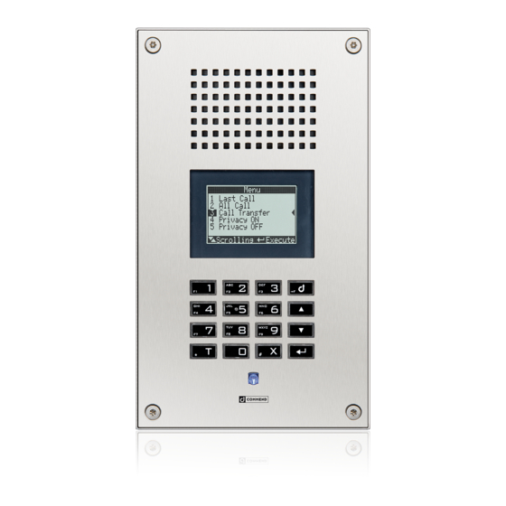
Appendix Commend SIP Series Display Menu WS 800V / WS 800F Following sections provide display menu operating instructions for the SIP stations WS 800V and WS 800F. LCD graphic display Alpha numeric full keypad Menu button Arrow buttons Up / Down... -
Page 67: Call Initiation At Sip-Ws 500F
Commend SIP Series Appendix Note: The volume can also be controlled during an active conversation. With the respective volume is saved also for the next conversation (as described above). Status Here the station data is indicated, like e.g. IP address, registration status, version. - Page 68 Appendix Commend SIP Series Allow Arbitrary Dailing activated After a the Enter button is pressed, the entered call number is dialled. If no button is pressed within a timeout of 10 seconds, then a double tone is put out and input mode is restarted, i.e. a new number can be dialled ...
-
Page 69: Technical Support
Commend SIP Series Technical Support Technical Support For more information about the Commend SIP Series visit: www.commend.com/sip 2.0/0612...
Need help?
Do you have a question about the SIP Series P and is the answer not in the manual?
Questions and answers