Kyocera FS-9530DN Service Manual
Hide thumbs
Also See for FS-9530DN:
- Advanced operation manual (172 pages) ,
- Operation manual (84 pages) ,
- Specification (2 pages)

Related Manuals for Kyocera FS-9530DN


Summary of Contents for Kyocera FS-9530DN
-
Page 1: Service Manual
FS-9130DN FS-9530DN SERVICE MANUAL Published in April 2007 842GZ113 2GZSM063 Rev. 3... - Page 2 CAUTION RISK OF EXPLOSION IF BATTERY IS REPLACED BY AN INCORRECT TYPE. DISPOSE OF USED BATTERIES ACCORDING TO THE INSTRUCTIONS. It may be illegal to dispose of this battery into the municipal waste stream. Check with your local solid waste officials for details in your area for proper disposal. ATTENTION IL Y A UN RISQUE D’EXPLOSION SI LA BATTERIE EST REMPLACEE PAR UN MODELE DE TYPE INCORRECT.
-
Page 3: Revision History
Revision history Revision Date Replaced pages Remarks June 16, 2006 Contents, 1-1-1, 1-1-2, 1-2-3, 1-3-3, 1-3-5, 1-3-10, 1-3-20, 1-3-21, 1-3-22, 1-5-21, 1-5-24, 1-5-25, 1-6-5, 2-2-1, 2-2-2, 2-3-4, 2-3-8, 2-3-12, 2-4-1, 2-4-2 February 6, 2007 Contents, 1-1-1, 1-1-2, 1-2-1, 1-2-5, 1-2-8 to 1-2-12, 1-3-1, 1-3-3, 1-3-6 to 1-3-8, 1-3-10, 1-3-13 to 1-3-16, 1-3-18, 1-3-19, 1-3-27 to 1-3-34, 1-4-2, 1-4-7, 1-4-9 to 1-4-17, 1-4-23, 1-4-24, 1-4-26,... - Page 4 This page is intentionally left blank.
-
Page 5: Safety Precautions
Safety precautions This booklet provides safety warnings and precautions for our service personnel to ensure the safety of their customers, their machines as well as themselves during maintenance activities. Service personnel are advised to read this booklet carefully to familiarize themselves with the warnings and precautions described here before engaging in maintenance activities. - Page 6 Safety warnings and precautions Various symbols are used to protect our service personnel and customers from physical danger and to prevent damage to their property. These symbols are described below: DANGER: High risk of serious bodily injury or death may result from insufficient attention to or incorrect compliance with warning messages using this symbol.
-
Page 7: Installation Precautions
1.Installation Precautions WARNING • Do not use a power supply with a voltage other than that specified. Avoid multiple connections to one outlet: they may cause fire or electric shock. When using an extension cable, always check that it is adequate for the rated current....................•... - Page 8 2.Precautions for Maintenance WARNING • Always remove the power plug from the wall outlet before starting machine disassembly....• Always follow the procedures for maintenance described in the service manual and other related brochures............................• Under no circumstances attempt to bypass or disable safety features including safety mechanisms and protective circuits.
- Page 9 • Do not remove the ozone filter, if any, from the copier except for routine replacement..... • Do not pull on the AC power cord or connector wires on high-voltage components when removing them; always hold the plug itself...................... •...
- Page 10 This page is intentionally left blank.
-
Page 11: Table Of Contents
2GZ/2G1-2 CONTENTS 1-1 Specifications 1-1-1 Specifications............................1-1-1 1-1-2 Parts names............................1-1-3 (1) Body ..............................1-1-3 (2) Operation panel..........................1-1-4 1-1-3 Machine cross section ..........................1-1-5 1-2 Installation 1-2-1 Installation environment .........................1-2-1 1-2-2 Unpacking and installation ........................1-2-2 (1) Installation procedure ........................1-2-2 1-2-3 Installing the network interface card (option) ..................1-2-9 1-2-4 Installing the hard disk unit (option) ......................1-2-10 1-2-5 Installing the CompactFlash card (option) ....................1-2-11 1-2-6 Installing the USB memory (option) ......................1-2-11... - Page 12 2GZ/2G1-2 1-5-2 Paper feed section ..........................1-5-2 (1) Detaching and refitting the forwarding, paper feed and separation pulleys ........1-5-2 (2) Detaching and refitting the MP separation, MP paper feed and MP forwarding pulleys ....1-5-4 (3) Detaching and refitting the left and right registration cleaner ............1-5-9 1-5-3 Laser scanner unit ..........................1-5-11 (1) Detaching and refitting the laser scanner unit .................1-5-11 (2) Adjusting the skew of the laser scanner unit (reference) ..............1-5-13...
- Page 13 2GZ/2G1-2 INSTALLATION GUIDE PAPER FEEDER 3000 SHEETS PAPER FEEDER DOCUMENT FINISHER 3000 SHEETS DOCUMENT FINISHER CENTER-FOLDING UNIT MAILBOX HOLE PUNCH UNIT...
- Page 14 2GZ/2G1 This page is intentionally left blank.
-
Page 15: Specifications
2GZ/2G1-2 1-1 Specifications 1-1-1 Specifications Type ..........Desktop Printing system ....... Indirect electrostatic system Printing paper ......... Weight Cassette: 60 - 105 g/m MP tray: 45 - 200 g/m Types Cassette: Plain, Preprinted, Bond, Recycled, Rough, Letterhead, Color, Prepunched, High quality, and Custom MP tray: Plain, Transparency, Preprinted, Labels, Bond, Recycled, Vellum, Rough, Letterhead, Color, Prepunched, Envelope, Cardstock, Thick, High quality, and Custom... - Page 16 2GZ/2G1-2 Controller ........PowerPC 750 FL (600MHz) Code ROM: 8 MB Font ROM: 4 MB Interface: 1 slot (100pin DDR-SDRAM DIMM) Memory: Standard 64 MB/Maximum 576 MB (40 ppm model ) Standard 128 MB/Maximum 640 MB (50 ppm model ) Memory card: 1 slot (CompactFlash card) Applicable OS .........Microsoft Windows 95/98/Me/2000/XP Microsoft Windows NT4.0...
-
Page 17: Parts Names
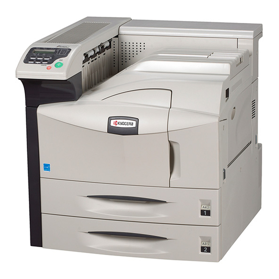
2GZ/2G1 1-1-2 Parts names (1) Body Figure 1-1-1 Operation panel 11. Toner container 21. Memory card slot Front cover 12. Toner container release lever 22. Option interface slot (OPT) Cassette 2 13. Waste toner box 23. Option memory slot cover Paper guide 14. - Page 18 2GZ/2G1 (2) Operation panel Figure 1-1-2 GO key Attention indicator CANCEL key Message display OK key 10. Interface indicator MENU key 11. Paper size indicator Cursor keys 12. Paper type indicator Ready indicator 13. Paper jam indicator Data indicator 1-1-4...
-
Page 19: Machine Cross Section
2GZ/2G1 1-1-3 Machine cross section Light path Paper path Figure 1-1-3 Machine cross section Paper feed section Main charging section Laser scanner unit Developing section Transfer and separation section Cleaning and charge erasing section Fuser section Eject and switchback section Duplex section 1-1-5... - Page 20 2GZ/2G1 This page is intentionally left blank. 1-1-6...
-
Page 21: Installation Environment
2GZ/2G1-2 1-2 Installation 1-2-1 Installation environment ° ° Temperature: 10 to 32.5 C/50 to 90.5 Humidity: 15 to 80%RH Power supply: 120 V AC, max. 11.4 A 220 to 240 V AC, max. 6.1 A ± ± Power source frequency: 50 Hz 0.3%/60 Hz 0.3% Installation location... -
Page 22: Unpacking And Installation
2GZ/2G1 1-2-2 Unpacking and installation (1) Installation procedure Start Unpacking. Remove the tapes. Install the optional paper feeder. Release of cassette lift plate. Load paper. Install the toner container. Install the waste toner box. Connecting the printer to the computer. Connect the power cord. - Page 23 2GZ/2G1-1 Unpacking. Figure 1-2-2 Unpacking Printer 11. Upper right pad Outer case 12. Spacer Inner frame 13. Toner container Skid 14. Hinge joints Bottom front left pad 15. Bar code labels Bottom front right pad 16. Plastic bag Bottom rear left pad 17.
- Page 24 2GZ/2G1 Remove the tapes. 1. Remove three tapes. Tapes Tape Figure 1-2-3 Install the optional paper feeder. 1. Install the optional paper feeder as necessary. Release of cassette lift plate. 1. Pull cassette 1 and 2 out. Lift plate stopper Remove the lift plate stopper from each cas- sette and attach it to the storage location.
- Page 25 2GZ/2G1-2 Load paper. 1. Pull the cassette out. Paper guide 2. Holding the paper size adjusting tab both ends, move the paper guide to fit the paper size. Paper size adjusting tab Figure 1-2-5 3. Adjust the paper stopper to fit the paper size.
- Page 26 2GZ/2G1 Install the toner container. 1. Open the front cover. Toner container 2. Lightly tap the top of the toner container five to six times. Figure 1-2-8 3. Thoroughly shake the toner container (in the Toner container direction of the arrows) ten times or more to loosen and mix the toner inside.
- Page 27 2GZ/2G1 Install the waste toner box. 1. Install the waste toner box in the machine. Waste toner box 2. Close the front cover. Figure 1-2-11 Connecting the printer to the computer. 1. There are various ways of connecting the printer to the computer, such as through the parallel interface connector, USB interface connector, or through the network interface connector.
- Page 28 2GZ/2G1-2 Connect the power cord. 1. Connect the power cord to the connector at the rear side of the machine. 2. Insert the power plug into the wall outlet. Printing a status page. 1. Turn the main switch on and the toner is supplied to the development unit for approx- imately 8 minutes.
-
Page 29: Installing The Network Interface Card (Option)
2GZ/2G1-2 1-2-3 Installing the network interface card (option) Procedure 1. Remove two screws and remove the inter- face slot cover (OPT). Interface slot cover Figure 1-2-13 2. Insert the network interface card and secure Network interface card it with the screws removed in step 1. Figure 1-2-14 3. -
Page 30: Installing The Hard Disk Unit (Option)
2GZ/2G1-2 1-2-4 Installing the hard disk unit (option) Procedure 1. Remove two screws and remove the slot cover (HDD). Slot cover Figure 1-2-16 2. Insert the hard disk unit into the slot. Hard disk unit Figure 1-2-17 3. Tighten two screws to secure the hard disk unit. -
Page 31: Installing The Compactflash Card (Option)
2GZ/2G1-2 1-2-5 Installing the CompactFlash card (option) Procedure 1. Turn the main switch off. CF card Note: Do not insert or remove a CF card while power in on. If the CF card is removed while the machine is on, damage could result in the machine's electronics or the CF card. -
Page 32: Installing The Expansion Memory (Option)
2GZ/2G1-2 1-2-7 Installing the expansion memory (option) Procedure Memory slot cover 1. Remove the screw at the rear side of the machine and remove the memory slot cover. Figure 1-2-21 2. Open the clips on both ends of the DIMM Socket socket. -
Page 33: Maintenance Mode
2GZ/2G1-2 1-3 Maintenance Mode 1-3-1 Maintenance mode (1) Maintenance mode The printer is equipped with a maintenance function which can be used to maintain and service the machine. To run the maintenance mode, Insert a compact flash card to which the maintenance program has been written into the printer and load the maintenance mode program to the printer using either method. - Page 34 2GZ/2G1 Continue from the previous page Setting the paper size >Set Bulk Feeder for the paper feeder [U208] Size >Set Folio Size Setting folio size See page 1-3-13. [U035] ######## See page 1-3-5. Setting punch destina- >Punch Dest. tion Checking the printer [U234] ##### >Check Cover SW>...
-
Page 35: Contents Of Maintenance Mode Items
2GZ/2G1-2 (3) Contents of maintenance mode items Maintenance Description item No. Setting the factory default data U002 Description Restore the machine conditions to the factory default settings. Purpose To return the machine settings to initial settings. Method 1. Enter the maintenance mode and press the cursor up/down keys to display [U002]. 2. - Page 36 2GZ/2G1 Maintenance Description item No. Checking motor operation U030 Description Drives each motor. Purpose To check the operation of each motor. Method 1. Enter the maintenance mode and press the cursor up/down keys to display [U030]. >Drive Motors > [U030] 2.
- Page 37 2GZ/2G1-1 Maintenance Description item No. Checking clutch operation U032 Description Turns each clutch on. Purpose To check the operation of each clutch. Method 1. Enter the maintenance mode and press the cursor up/down keys to display [U032]. >Check Clutches> [U032] 2.
- Page 38 2GZ/2G1-2 Maintenance Description item No. Checking the printer cover switch U038 Description Displays the on-off status of each cover switch. Purpose To check if the switches of covers operate correctly. Method 1. Enter the maintenance mode and press the cursor up/down keys to display [U038]. >Check Cover SW>...
- Page 39 2GZ/2G1-2 Maintenance Description item No. Setting the adjustment of the motor speed U053 Description Performs fine adjustment of the speeds of the motors. Purpose To adjust the speed of the respective motors when the magnification is not correct. Method 1. Enter the maintenance mode and press the cursor up/down keys to display [U053]. >Adjust Motor >...
- Page 40 2GZ/2G1-2 Maintenance Description item No. Setting the other high voltages U101 Description Sets the developing bias control voltage, the transfer control voltage, and the separation control voltage or checks the output of these voltages. Purpose To check the developing bias, the transfer voltage and the separation voltage or to take measures against drop of image density or background fog.
- Page 41 2GZ/2G1 Maintenance Description item No. Setting the cleaning interval for the main charger U102 Description Changes the intervals at which the main charger is cleaned. Purpose To change the setting when the background is visible. Setting 1. Enter the maintenance mode and press the cursor up/down keys to display [U102]. 2.
- Page 42 2GZ/2G1-2 Maintenance Description item No. Setting separation charger mode U114 Description Sets the separation charger mode. Purpose If the fuser offset occurs, change the setting. Method 1. Enter the maintenance mode and press the cursor up/down keys to display [U114]. >Setting AC Mode [U114] Mode 1...
- Page 43 2GZ/2G1 Maintenance Description item No. Setting toner loading operation U144 Description Sets toner loading operation after completion of printing. Purpose To set whether or not toner is loaded on the drum after low density printing. Normally no change is necessary from the initial setting.
- Page 44 2GZ/2G1 Maintenance Description item No. Turning the fuser heater on U196 Description Turns the fuser heater M or S on. Purpose To check fuser heaters turning on. Method 1. Enter the maintenance mode and press the cursor up/down keys to display [U196]. >Turn Fixing >...
- Page 45 2GZ/2G1-2 Maintenance Description item No. Setting the paper size for the paper feeder U208 Description Sets the size of paper used in optional 3000-sheet paper feeder. Purpose To change the setting when the size of paper used in the paper feeder is changed. Method 1.
- Page 46 2GZ/2G1-2 Maintenance Description item No. Setting finisher stack quantity U237 Description Sets the number of sheets of each stack on the main tray and on the internal tray in the optional finisher. Purpose To change the setting when a stack malfunction has occurred. Method 1.
- Page 47 2GZ/2G1-2 Maintenance Description item No. Setting the finisher U246 Description Provides various settings for the optional finisher, if furnished. Purpose Adjustment of registration stop timing in punch mode Adjust if skewed paper conveying occurs or if the paper is Z-folded in punch mode. Adjustment of paper stop timing in the punch mode To adjust this item when the position of a punch hole is different from the specified one.
- Page 48 2GZ/2G1-2 Maintenance Description item No. Setting: adjustment of registration stop timing U246 1. Select [>>Punch Reg]. 2. Press the OK key. [ _ ] will blink. 3. Press the cursor right/left keys to move [ _ ] to the digit position at which the value is to be changed and press the cursor up/down keys to change the preset value.
- Page 49 2GZ/2G1 Maintenance Description item No. Setting: adjustment of front/rear side registration home position U246 1. Select [>>Width F HP] or [>>Width R HP]. 2. Press the OK key. [ _ ] will blink. 3. Press the cursor right/left keys to move [ _ ] to the digit position at which the value is to be changed and press the cursor up/down keys to change the preset value.
- Page 50 2GZ/2G1-2 Maintenance Description item No. Setting: adjustment of upper/lower side registration home position U246 1. Select [>>Width U HP] or [>>Width L HP]. 2. Press the OK key. [ _ ] will blink. 3. Press the cursor right/left keys to move [ _ ] to the digit position at which the value is to be changed and press the cursor up/down keys to change the preset value.
- Page 51 2GZ/2G1-2 Maintenance Description item No. Setting: adjustment of center folding position U246 Check the booklet stapling position is correct before adjusting the center folding position. 1. Select [>>Booklet Pos 1], [>>Booklet Pos 2] or [>>Booklet Pos 3]. 2. Press the OK key. [ _ ] will blink. 3.
- Page 52 2GZ/2G1-1 Maintenance Description item No. Outputs of the history of events of the service calls and paper jam U392 Description Outputs the history of events conditions of the service calls and paper jam. Purpose To check the event conditions of the service calls and paper jam. Method 1.
- Page 53 2GZ/2G1-1 Maintenance Description item No. Adjusting the leading edge margin of image printing for each paper cassette U394 Description Adjusts the leading edge margin of image printing for each paper cassette. Purpose To adjust the leading edge margin if it is displaced depending on the paper cassette. Method 1.
- Page 54 2GZ/2G1-1 Maintenance Description item No. Displaying the amount of paper remaining in each paper cassette U396 Description Displays the amount of paper remaining in each paper cassette. Purpose To check the amount of paper remaining in each paper cassette. Method 1.
- Page 55 2GZ/2G1 Maintenance Description item No. Setting FRPO U399 Description Set the firmware again. Purpose To change the preset values of firmware. Method 1. Enter the maintenance mode and press the cursor up/down keys to display [U399]. >Set FRPO > [U399] Parameter 2.
-
Page 56: Service Mode
2GZ/2G1 1-3-2 Service mode The printer is equipped with a maintenance function which can be used to maintain and service the machine. (1) Executing a service item Message display Ready 1. Press the MENU key. Print Menu Map 2. Press the cursor up/down keys several times until [Others >] is displayed. -
Page 57: Description Of Service Mode
2GZ/2G1 (2) Description of service mode Service items Description Printing a status page for service purpose Description Prints a status page for service purpose. The status page includes various printing settings >>Print and service cumulative. Status Page Purpose To acquire the current printing environmental parameters and cumulative information. Procedure Enter the service mode [>>Print Status Page]. -
Page 58: Service Information
2GZ/2G1 Service items Description Service information Service information [XXXXXXXX/XXXXXXXX][XXXXXXX][XXXXXXXX][01/00] Printed Page(s) 9690 /t/P00/S00/U00/F00/N00/D50:DM0301.DAN:0002001001210052 /0020/0020/1061/0811/ 0/ 0/ 0/ 0/ 0/ 0/ 0/ /AAAAAAA/AAAAAAA/AAAAAAA/ /AAAAAAA/AAAAAAA/AAAAAAA/ /AAAAAAA/ /AAAAAAA/ /AAAAAAA/AAAAAAA/AAAAAAA/ /AAAAAAA/AAAAAAA/AAAAAAA/AAAAAAA/AAAAAAA/ /0000/0000/0000/0000/0000/ /0000/ /RS2/FF/[0003-0003]/81/31/50/0 00.00.00.00.00.00 A:1234567890123456 /03030303/03030303/03030303/03000000/00000000/03030303/03030303/ SPD1:0203040508090A0B0C0D0F101112131415161718191A1B1C1D1E1F202122235E /00000000/00000000/00000000000000000000000000000000/00000000000000000000000000000000/0000/00/00 /0000000000000000/0000000000000000/0000000000000000/0000000000000000/ /0000000000000000/0000000000000000/0000000000000000/0000000000000000/ /0000000000000000/0000000000000000/0000000000000000/0000000000000000/ /0000000000000000/0000000000000000/0000000000000000/0000000000000000/ DN:SPL9200007 SN:SPL9200010 Detail of service information Items Description... - Page 59 2GZ/2G1-2 Service items Description Items Description Software jumper switch [First byte/second byte] information First byte Second byte: (hexadecimal) bit 0 = 1: (Fixed) Displayed in OEM mode only. bit 1 = 0: Overseas, 1: Domestic (Japan) bit 2, 3 (Not used) bit 4 = 0: KC, 1: OEM bit 5 = 0: For Europe, 1: For US bit 6 = 0: Non MICR mode,...
- Page 60 2GZ/2G1-2 Service items Description Items Description Paper source position counter /Duplex/ Life counter of each unit /Drum unit/Developer unit/Fuser unit/ Document finisher counter /Document finisher total/Main tray total/Centerfold unit/Punch unit/Sta- pler/ Version of each unit /3000-sheet paper feeder/Document finisher (software)/Mailbox/Center- fold unit/Internal tray (3000-sheet document finisher) Drum ID Serial interface information...
- Page 61 2GZ/2G1-2 Service items Description Printing an event log (EVENT LOG) Description >>Print Prints the history of paper misfeeds and self-diagnostic errors including up to 16 items from Event Log the latest occurrence of such an error. (If the number of errors exceeds 16, errors will be deleted sequentially from the oldest one.) Purpose To allow machine malfunction analysis based on the frequency of paper misfeeds and self...
- Page 62 2GZ/2G1-2 Service items Description Detail of event log (EVENT LOG) information Items Description Engine PWB mask version [Engine mask version/Engine software version] Operation panel PWB mask ver- sion BROM version Software jumper switch informa- [First byte/Second byte] tion (hexadecimal) First byte bit 0 = 1: (Fixed) Second byte: bit 1 = 0: Overseas, 1: Domestic (Japan)
- Page 63 2GZ/2G1-2 Service items Description Items Description (10) (a) Cause of paper jam (Hexadecimal) cont. 04: Cover opened. [00] 05: Memory read ready time-out (secondary paper feed does not start). [4D] 09: Sequence error (3000-sheet paper feeder). [33] 10: No paper feed (cassette 1). [31] 11: No paper feed (cassette 2).
- Page 64 2GZ/2G1-2 Service items Description Items Description (10) (b) Detail of jam location (Hexadecimal) cont. PES1 PES1 PES1 (Trays 1 to 7) TEJS TEJS TEJS REVS REVS REVS PES2 PES2 PES2 Document finisher Mailbox (Left (Left (Left TEJS TEJS TEJS sub tray) sub tray) sub tray) MPESW...
- Page 65 2GZ/2G1-2 Service items Description Items Description (10) (d) Detail of paper size (Hexadecimal) cont. 01: Monarch 0C: Ledger 23: Special 2 02: Business 0D: A5R 24: A3 wide 03: International DL 8D: A5E 25: Ledger wide 04: International C5 0E: A6 26: Full bleed paper (12 ×...
- Page 66 2GZ/2G1-2 Service items Description Items Description (11) Service Call (Self diag- Count. Self diagnostic error nostic error) Log code Remembers 1 to 8 of The total page count at Indicates the self occurrence of self diag- the time of the self diag- diagnostic errors and nostics error.
- Page 67 2GZ/2G1 Service items Description Setting the paper feed operation (printer driver priority mode) Description >>Paper Feed With printer driver priority mode, when selecting the specific paper feed location (a cassette or MP tray) with the printer driver (it is not automatic selection), paper is fed from the selected location.
- Page 68 2GZ/2G1 Service items Description Drum surface refreshing Description Rotates the drum approximately 3 minutes with toner lightly on the overall drum using the >>Drum high-voltage output control of the engine PWB. The cleaning blade in the drum unit scrapes toner off the drum surface to clean it. Purpose To clean the drum surface when image failure occurs due to the drum.
-
Page 69: Paper Misfeed Detection
2GZ/2G1 1-4 Troubleshooting 1-4-1 Paper misfeed detection (1) Paper misfeed indication When a paper misfeed occurs, the machine immediately stops printing and displays the jam location on the operation panel. To remove paper jammed in the machine, open the front cover, left cover or pull the cassette out. To remove the jammed paper in optional document finisher, detach the finisher from the machine. - Page 70 2GZ/2G1-2 Section Description Conditions Specified time System Cover is open during printing. Cover open Secondary paper feed does not start within specified time 30 s Secondary paper feed of arrival of paper at the registration section. does not start A communication sequence error occurs between the 3000-sheet paper machine and the 3000-sheet paper feeder.
- Page 71 2GZ/2G1 Section Description Conditions Specified time Paper The registration switch (RSW) does not turn on within 1283 ms feed Misfeed in vertical specified time of feed switch 1 (FSW1) turning on. section paper conveying sec- Feed switch 1 (FSW1) does not turn on within specified 1478 ms tion time of feed switch 2 (FSW2) turning on.
- Page 72 2GZ/2G1-3 Section Description Conditions Specified time Paper The feed switch 1 (FSW1) does not turn off within speci- 1478 ms feed Multiple sheets in verti- fied time of the feed switch 2 (FSW2) turning off. section cal conveying section The feed switch 2 (FSW2) does not turn off within speci- 1539 ms fied time of the feed switch 3 (FSW3) turning off.
- Page 73 2GZ/2G1 Section Description Conditions Specified time Feedshift The feedshift switch (FSSW) does not turn on within 1196 ms section Misfeed in feedshift specified time of the start of eject motor (EM) reverse section rotation. During paper switchback operation, the feedshift switch 2313 ms (FSSW) does not turn off within specified time of the its turning on.
- Page 74 2GZ/2G1 Section Description Conditions Specified time Optional (3000-sheet document finisher) 1182 ms finisher Exit sensor stay jam Eject switch 1 (ESW1) is not turned off within specified time of its turning on. (Document finisher) 1680 ms In the straight mode, the exit sensor (EXS) is not turned off within specified time of its turning on.
- Page 75 2GZ/2G1-2 Section Description Conditions Specified time Optional The centerfold paper entry sensor (CPES) does not turn 1370 ms finisher Jam in centerfold unit off within specified time of centerfold paper detection sen- (3000-sheet document sor (CPDS) turning on. finisher only) The centerfold paper entry sensor (CPES) does not turn 1370 ms on within specified time of centerfold paper detection sen-...
- Page 76 2GZ/2G1 Section Description Conditions Specified time Optional The reverse sensor (REVS) does not turn on within spec- 1071 ms finisher Reverse sensor jam ified time of paper entry sensor (PES) turning on. (document finisher The reverse sensor (REVS) is not turned on within speci- 435 ms only) fied time.
-
Page 77: Paper Misfeeds
2GZ/2G1-2 (3) Paper misfeeds Problem Causes/check procedures Corrective measures A piece of paper torn from Check visually and remove it, if any. A paper jam in the print paper is caught around paper feed, convey- feed switch 1/2/3, registra- ing or eject section is tion switch, eject switch or indicated as soon as feedshift switch. - Page 78 2GZ/2G1-2 Problem Causes/check procedures Corrective measures Optional paper feeder A paper jam in the Paper is extremely curled. Change the paper. paper feed section is indicated during Check if the paper feed pul- Check visually and replace any deformed pulleys. printing (no paper ley, forwarding pulley and feed from optional...
- Page 79 2GZ/2G1-2 Problem Causes/check procedures Corrective measures Paper is extremely curled. Change the paper. A paper jam in the Check if the MP paper feed Check visually and replace any deformed pulleys. paper feed section is pulley, MP forwarding pulley indicated during and MP separation pulley printing (no paper are deformed.
- Page 80 2GZ/2G1-2 Problem Causes/check procedures Corrective measures (10) Broken feed switch 1/2/3 Check visually and replace switch. A paper jam in the actuator. paper feed section is Defective switch. Run maintenance item U031 and turn following switch on and off indicated during manually.
- Page 81 2GZ/2G1-2 Problem Causes/check procedures Corrective measures (14) Broken feed switch 1/2/3 Check visually and replace switch. A paper jam in the actuator. paper feed section is Defective switch. Run maintenance item U031 and turn switch on and off manually. indicated during Replace the switch if indication of the corresponding switch on the printing (multiple touch panel is not displayed in reverse.
- Page 82 2GZ/2G1-2 Problem Causes/check procedures Corrective measures (19) Electrical problem with the Check (see page 1-4-38). A paper jam in the feedshift solenoid. feedshift section is Broken feedshift switch Check visually and replace switch. indicated during actuator. printing (jam in feed- shift section).
- Page 83 2GZ/2G1-2 Problem Causes/check procedures Corrective measures (24) Defective staple home posi- With 5 V DC present at YC22-6 on the finisher main PWB, check if A paper jam in tion sensor. YC22-5 on the finisher main PWB remains low or high when the optional document staple home position sensor is turned on and off.
- Page 84 2GZ/2G1-2 Problem Causes/check procedures Corrective measures (29) Defective internal tray With 5 V DC present at YC11-4 on the internal tray PWB, check if A paper jam in paper entry sensor 2. YC11-5 on the internal tray PWB remains low or high when the optional document internal tray paper entry sensor 2 is turned on and off.
- Page 85 2GZ/2G1-2 Problem Causes/check procedures Corrective measures (33) Defective eject sensor. With 5 V DC present at CN5-4 on the finisher main PWB, check if A paper jam in CN5-6 on the finisher main PWB remains low or high when the optional document eject sensor is turned on and off.
-
Page 86: Self-Diagnosis
2GZ/2G1 1-4-2 Self-diagnosis (1) Self-diagnostic function This unit is equipped with a self-diagnostic function. When a problem is detected, printing is disabled and the problem dis- played a number, indicating the nature of the problem. A message is also displayed requesting the user to call for service. After removing the problem, the self-diagnostic function can be reset by turning safety switches off and back on. - Page 87 2GZ/2G1 Remarks Code Contents Causes Check procedures/corrective measures 1020 Lower lift motor error Poor contact in the Check the connection of connector of lower When cassette 2 is inserted, lower lift connector termi- lift motor and the connector YC13 on the limit switch does not turn on within 12 s nals.
- Page 88 2GZ/2G1 Remarks Code Contents Causes Check procedures/corrective measures 1100 Paper feeder lift motor 1 error Poor contact in the Check the connection of connector on the (optional 3000-sheet paper feeder) connector termi- engine PWB and the connector on the paper A motor over-current signal is detected nals.
- Page 89 2GZ/2G1 Remarks Code Contents Causes Check procedures/corrective measures 1800 Paper feeder unit communication Poor contact in the Check the connection of connector on the problem (optional paper feeder/3000- connector termi- engine PWB and the connector on the paper sheet paper feeder) nals.
- Page 90 2GZ/2G1 Remarks Code Contents Causes Check procedures/corrective measures 2500 Paper feed motor error Poor contact in the Check the connection of connector YC11 on Stable OFF is detected for 1 s continu- connector termi- the engine PWB and the connector on the ously after paper feed motor stability.
- Page 91 2GZ/2G1-2 Remarks Code Contents Causes Check procedures/corrective measures 4200 BD steady-state problem Poor contact in the Check the connection of connector YC8 on ASIC detects a BD error A for 2 s after connector termi- the engine PWB and laser scanner unit, and the polygon motor rotation has been sta- nals.
- Page 92 2GZ/2G1-2 Remarks Code Contents Causes Check procedures/corrective measures 6410 Fuser unit connector insertion prob- Fuser unit connec- Reinsert the fuser unit connector if neces- tor inserted incor- sary. Absence of the fuser unit is detected. rectly. Defective fuser unit Replace the fuser unit. connector.
- Page 93 2GZ/2G1 Remarks Code Contents Causes Check procedures/corrective measures 8020 Punch motor problem (optional 3000- Poor contact in the Check the connection of connector on the sheet document finisher) connector termi- punch PWB and the continuity across the The LOCK signal of the punch motor is nals.
- Page 94 2GZ/2G1-2 Remarks Code Contents Causes Check procedures/corrective measures 8070 Internal tray communication error Poor contact in the Check the connection of connector YC6 on (optional 3000-sheet document fin- connector termi- the finisher main PWB and the connector isher) nals. YC1 on the internal tray PWB, and the conti- Communication with the internal tray is nuity across the connector terminals.
- Page 95 2GZ/2G1 Remarks Code Contents Causes Check procedures/corrective measures 8170 Side registration motor 1 problem Poor contact in the Check the connection of connector YC2 on (optional 3000-sheet document fin- connector termi- the internal tray PWB and the connector on isher) nals.
- Page 96 2GZ/2G1 Remarks Code Contents Causes Check procedures/corrective measures 8210 Stapler shift motor 1 error (optional Poor contact in the Check the connection of connector YC9 on 3000-sheet document finisher) connector termi- the finisher main PWB and the connector of When operation returned to a home nals.
- Page 97 2GZ/2G1 Remarks Code Contents Causes Check procedures/corrective measures 8310 Centerfold side registration motor 1 Poor contact in the Check the connection of connector YC6 on problem (optional centerfold unit of connector termi- the centerfold main PWB and the connector 3000-sheet document finisher) nals.
- Page 98 2GZ/2G1-2 Remarks Code Contents Causes Check procedures/corrective measures 8360 Centerfold main motor problem Poor contact in the Check the connection of connector YC12 on (optional centerfold unit of 3000-sheet connector termi- the centerfold main PWB and the connector document finisher) nals.
- Page 99 2GZ/2G1-2 Remarks Code Contents Causes Check procedures/corrective measures 8900 Backup memory data problem Poor contact in the Check the connection of connector on the (optional 3000-sheet document fin- connector termi- finisher main PWB and the connector on the isher) nals. engine PWB, and the continuity across the Read and write data does not match.
-
Page 100: Image Formation Problems
2GZ/2G1-2 1-4-3 Image formation problems (1)No image appears (2)No image appears (3)Image is too light. (4)Background is (5)A white line (entirely white). (entirely black). visible. appears longitudi- nally. See page 1-4-33. See page 1-4-33. See page 1-4-34. See page 1-4-34. See page 1-4-34. - Page 101 2GZ/2G1-2 (1) No image appears (entirely white). Print example Causes Check procedures/corrective measures No trans- The connector terminals Reinsert the connector. Also check for continuity within the fer charg- of the high voltage PWB connector cable. If none, remedy or replace the cable. ing.
-
Page 102: Background Is Visible
2GZ/2G1-2 (3) Image is too light. Print example Causes Check procedures/corrective measures Insufficient toner. If the display shows the message requesting toner replenish- ment, replace the container. Deteriorated toner. Perform the drum refresh operation. Defective The connector terminals Reinsert the connector. Also check for continuity within the transfer of the high voltage PWB connector cable. -
Page 103: A Black Line Appears Laterally
2GZ/2G1-2 (7) A black line appears laterally. Print example Causes Check procedures/corrective measures Flawed drum. Replace the drum unit (see page 1-5-14). Dirty developing section. Clean any part contaminated with toner in the developing section. Leaking main charger housing. Clean the main charger wire and grid. Leaking separation electrode. -
Page 104: The Leading Edge Of The Image Is Sporadically Misaligned
2GZ/2G1-2 (11) The leading edge of the image is sporadically misaligned Print example Causes Check procedures/corrective measures Feed clutch, paper feed clutch, MP Check the installation position and operation of each clutch. paper feed clutch or registration If any of them operates incorrectly, replace it. clutch installed or operating incor- rectly. -
Page 105: Fusing Is Poor
2GZ/2G1-2 (15) Fusing is poor. Print example Causes Check procedures/corrective measures Wrong types of paper. Check if the paper meets specifications. Replace paper. Defective pressure springs. Replace the pressure springs. Flawed press roller. Replace the press roller (see page 1-5-21). Flawed fuser heater. -
Page 106: Electric Problems
2GZ/2G1 1-4-4 Electric problems Troubleshooting to each failure must be in the order of the numbered symptoms. Problem Causes Check procedures/corrective measures 1. The power cord is not Check the contact between the power plug and the outlet. The machine does plugged in properly. - Page 107 2GZ/2G1 Problem Causes Check procedures/corrective measures 1. Broken main charger (See page 1-4-33.) Main charging is not wire. performed. 2. Leaking main charger housing. 3. The connector terminals of the high voltage PWB make poor contact. 4. Defective engine PWB. 5.
- Page 108 2GZ/2G1-2 Problem Causes Check procedures/corrective measures (11) 1. A piece of paper torn Check visually and remove it, if any. A paper jam in the from print paper is caught paper feed, paper around feed switch 1/2/3, conveying, fuser, registration switch, feed- eject or duplex sec- shift switch, eject switch tion is indicated when...
-
Page 109: Mechanical Problems
2GZ/2G1 1-4-5 Mechanical problems Problem Causes/check procedures Corrective measures Check if the surfaces of the following rollers or Clean with isopropyl alcohol. No primary paper feed. pulleys are dirty with paper powder: upper/ lower forwarding pulleys, upper/lower paper feed pulleys, upper/lower separation pulleys, feed rollers, registration rollers, MP forward- ing pulley, MP paper feed pulley and MP sep- aration pulley. - Page 110 2GZ/2G1 Problem Causes/check procedures Corrective measures Check if the developing unit is extremely dirty. Clean the developing unit. Toner drops on the paper conveying path. Check if the pulleys, rollers and gears operate Grease the bearings and gears. Abnormal noise is heard. smoothly.
-
Page 111: Assembly And Disassembly
2GZ/2G1 1-5 Assembly and Disassembly 1-5-1 Precautions for assembly and disassembly (1) Precautions Be sure to turn the main switch off and disconnect the power plug before starting disassembly. When handling PWBs (printed wiring boards), do not touch parts with bare hands. The PWBs are susceptible to static charge. -
Page 112: Paper Feed Section
2GZ/2G1 1-5-2 Paper feed section (1) Detaching and refitting the forwarding, paper feed and separation pulleys Follow the procedure below to replace the forwarding, paper feed and separation pulleys. Procedure Removing the primary paper feed units 1. Open the front cover and pull out the cassettes 1 and 2. - Page 113 2GZ/2G1 Removing the paper feed pulley Stop ring 7. Remove two stop rings from the primary paper feed unit. Stop ring 8. Pull the paper feed pulley shaft in the direc- tion of the arrow and remove the paper feed pulley.
-
Page 114: Detaching And Refitting The Mp Separation, Mp Paper Feed And Mp Forwarding Pulleys
2GZ/2G1-2 (2) Detaching and refitting the MP separation, MP paper feed and MP forwarding pulleys Follow the procedure below to replace the MP separation, MP paper feed and MP forwarding pulleys. Procedure Removing the MP unit 1. Remove four screws and remove the right lower cover. - Page 115 2GZ/2G1-2 5. Raise the MP separation shaft as shown in the figure, remove the holder plate and the bushing, and then remove the MP separa- tion pulley. Holder plate Take care not to remove the spring pin of the gear at the rear of the MP separation pulley Bushing shaft.
- Page 116 2GZ/2G1-2 9. Raise the MP paper feed pulley shaft as Stop ring shown in the figure, remove the stop ring, MP paper feed and then remove the MP paper feed pulley. pulley shaft MP paper feed pulley Figure 1-5-13 Removing the MP forwarding pulley Stop ring 10.
- Page 117 2GZ/2G1-2 13. Remove the stop ring of the MP paper feed pulley shaft and slide the bushing in the Stop ring Bushing direction of the arrow. MP paper feed pulley shaft Figure 1-5-16 14. Slide the MP forwarding pulley shaft tempo- MP forwarding rarily toward the rear side and then raise it to pulley shaft...
- Page 118 2GZ/2G1-2 16. Remove the stop ring and slide the MP for- warding pulley with the forwarding pulley retainer from the shaft to remove it. 17. Replace the MP separation, MP paper feed and MP forwarding pulleys. Stop ring MP forwarding pulley Forwarding pulley retainer Figure 1-5-19...
-
Page 119: Detaching And Refitting The Left And Right Registration Cleaner
2GZ/2G1 (3) Detaching and refitting the left and right registration cleaner Take the following procedure when the left or right registration cleaner is to be replaced. Procedure Removing the left registration cleaner Registration guide 1. Open the left cover 1 and remove the trans- Left registration roller fer roller unit. - Page 120 2GZ/2G1 Removing the right registration cleaner 1. Remove the developing unit and drum unit. (see pages 1-5-17 and 14). 2. Remove the right registration cleaner. 3. Replace the right registration cleaner and Install the cleaner. 4. Refit the drum unit and developing unit. Right registration cleaner Frame Figure 1-5-23...
-
Page 121: Laser Scanner Unit
2GZ/2G1 1-5-3 Laser scanner unit (1) Detaching and refitting the laser scanner unit Take the following procedure when the laser scanner unit is to be replaced. Procedure 1. Remove the developing unit and drum unit (see pages 1-5-14 and 17). 2. - Page 122 2GZ/2G1-2 6. Remove two screws and two connectors, Connectors and then remove the fan duct. Fan duct Figure 1-5-27 7. Remove six screws and remove the toner container retainer. Toner container retainer Figure 1-5-28 8. Remove two pins and two spring. Remove the screw and the connector, and then Connector remove the laser scanner unit.
-
Page 123: Adjusting The Skew Of The Laser Scanner Unit (Reference)
2GZ/2G1 (2) Adjusting the skew of the laser scanner unit (reference) Perform the following adjustment if the leading and trailing edges of the print image are laterally skewed (lateral square- ness not obtained). Since this adjustment uses the test page that is output from the maintenance mode, prepare the compact flash card to which the maintenance mode has been written and load the maintenance mode to the printer to carry out this adjustment (See page 1-3-1). -
Page 124: Drum Section
2GZ/2G1 1-5-4 Drum section (1) Detaching and refitting the drum unit Follow the procedure below to replace the drum unit. Cautions: Avoid direct sunlight or strong light when detaching and refitting the drum unit. Never touch the drum surface when holding the drum unit. Procedure 1. -
Page 125: Detaching And Refitting The Main Charger Unit
2GZ/2G1 (2) Detaching and refitting the main charger unit Follow the procedure below to replace the main charger unit. Procedure Inserted part 1. Remove the developing unit (see page 1-5- 17). 2. Release the inserted part and remove the connector cover. 3. -
Page 126: Detaching And Refitting The Drum Separation Claws
2GZ/2G1-2 (3) Detaching and refitting the drum separation claws Follow the procedure below to replace the drum separation claws. Procedure 1. Remove the developing unit (see page 1-5- 17). Drum unit 2. Remove the drum unit (see page 1-5-14). 3. Remove two screws and remove the lower cleaning seal. -
Page 127: Developing Section
2GZ/2G1-2 1-5-5 Developing section (1) Detaching and refitting the developing unit Follow the procedure below to replace the developing unit. Procedure Developing release lever 1. Open the front cover. 2. Remove the toner container and waste toner box. 3. Remove the pin and turn the developing release lever in the direction of the arrow. -
Page 128: Transfer Section
2GZ/2G1-2 1-5-6 Transfer section (1) Detaching and refitting the transfer roller unit Follow the procedure below to replace the transfer roller unit. Procedure 1. Open the left cover 1. Transfer roller unit 2. While holding down the projection, slide the transfer roller unit toward the front to remove 3. -
Page 129: Fuser Section
2GZ/2G1-2 1-5-7 Fuser section (1) Detaching and refitting the fuser unit Follow the procedure below to check or replace the fuser unit. Procedure 1. Open the front cover and left cover 1. 2. Remove two screws and remove front left cover. -
Page 130: Detaching And Refitting The Heat Roller Separation Claws
2GZ/2G1-2 (2) Detaching and refitting the heat roller separation claws Follow the procedure below to replace the heat roller separation claws. Procedure 1. Remove the fuser unit. (see page 1-5-19) 2. Remove the two pins and remove the upper Upper fuser cover fuser cover while holding the four claws. -
Page 131: Detaching And Refitting The Press Roller
2GZ/2G1-2 (3) Detaching and refitting the press roller Follow the procedure below to replace the press roller. Procedure 1. Remove the fuser unit (see page 1-5-19). Press spring 2. Remove the upper fuser cover (see page 1- 5-20). 3. Remove the front and rear press springs. Press spring Figure 1-5-45 4. -
Page 132: Detaching And Refitting The Fuser Heater
2GZ/2G1-2 (4) Detaching and refitting the fuser heater Follow the procedure below to replace the fuser heater. Procedure 1. Remove the fuser unit (see page 1-5-19). 2. Remove the upper fuser cover (see page 1- 5-20). 3. Remove two screws and the connector. Connector Figure 1-5-47 4. -
Page 133: Detaching And Refitting The Heat Roller
2GZ/2G1-2 (5) Detaching and refitting the heat roller Follow the procedure below to replace the heat roller. Procedure 1. Remove the fuser unit (see page 1-5-19). 2. Remove the upper fuser cover (see page 1- 5-20). 3. Remove the press roller and fuser heater (see page 1-5-21 and 22). -
Page 134: Detaching And Refitting The Fuser Unit Thermistor 1 And 2
2GZ/2G1-2 (6) Detaching and refitting the fuser unit thermistor 1 and 2 Follow the procedure below to replace the fuser unit thermistor 1 and 2. Procedure 1. Remove the fuser unit (see page 1-5-19). 2. Remove the upper fuser cover (see page 1- 5-20). -
Page 135: Others
2GZ/2G1-2 1-5-8 Others (1) Detaching and refitting the ozone filter 1 and 2 Follow the procedure below to replace the ozone filter 1 and 2. Procedure 1. Remove the ozone filter 1 from the machine left side. Ozone filter 1 Figure 1-5-53 2. -
Page 136: Detaching And Refitting The Dust Filter 1 And 2
2GZ/2G1-2 (2) Detaching and refitting the dust filter 1 and 2 Follow the procedure below to replace the dust filter 1 and 2. Procedure 1. Open the MP tray. 2. Remove the dust filter 1 and 2 from the machine. 3. -
Page 137: Downloading Firmware
2GZ/2G1 1-6 Firmware 1-6-1 Downloading firmware The system firmware can be update by downloading new firmware. Downloading can be made either by directly sending the new firmware from PC via the parallel interface or using a memory card that contains the new firmware. Firmware file name example Software ID Compression... -
Page 138: Downloading The Firmware From The Parallel Interface
2GZ/2G1-2 (1) Downloading the firmware from the parallel interface To download the system firmware using the parallel interface, use the procedure below. Procedure 1. Turn printer and PC power off. 2. Connect the parallel printer cable between the PC and the printer. Parallel printer cable Parallel... -
Page 139: Downloading The Firmware From The Memory Card
2GZ/2G1 (2) Downloading the firmware from the memory card The procedure below provides how to download firmware from a memory card. Procedure 1. Turn the main switch off. 2. Insert the memory card into the printer's memory card slot. Memory card slot Memory card Figure 1-6-4... - Page 140 2GZ/2G1 10. Confirm that the main switch is set to off. 11. Insert the memory card into the printer's memory card slot. Memory card slot Memory card Figure 1-6-7 12. Turn the main switch on. 13. When message display (1) is displayed to Main switch: On detect firmware in the memory card.
-
Page 141: Downloading The Firmware From The Usb Memory
2GZ/2G1-1 (3) Downloading the firmware from the USB memory The procedure below provides how to download firmware from a USB memory. Procedure 1. Turn the main switch off. 2. Connect the USB memory to the PC. Copy the firmware file to the root directory of the USB memory. - Page 142 2GZ/2G1 This page is intentionally left blank. 1-6-6...
-
Page 143: Paper Feed Section
2GZ/2G1-2 2-1 Mechanical construction 2-1-1 Paper feed section The paper feed section consists of the primary feed and secondary feed subsections. Primary feed conveys paper from the cassettes 1, 2 or MP tray to the left and right registration rollers, at which point secondary feed takes place and the paper travels to the transfer section in sync with the printing timing. - Page 144 2GZ/2G1 The MP tray can be hold up to 200 sheets of paper at one time. Paper is fed from the MP tray by the rotation of the MP for- warding pulley and MP paper feed pulley. Also during paper feed, the MP separation pulley prevents multiple sheets from being fed at one time by the torque limiter.
- Page 145 2GZ/2G1 EPWB YC14-B6 YC10-A2 FCL1 YC11-14 YC11-17 FSW1 PSW-U LICSW-U YC13-B9 PFCL-U YC13-B12 YC14-B1 FCL2 YC13-A12 PSW-L LICSW-L YC13-B15 FSW2 PFCL-L YC13-B18 YC14-B4 FCL3 YC13-A5 FSW3 YC13-A2 YC13-A7 Figure 2-1-3 Paper feed section block diagram (cassettes 1 and 2) MPPFCL MPFCL MPPSW MPFSW...
-
Page 146: Main Charging Section
2GZ/2G1-2 2-1-2 Main charging section The main charging section consists of the main charger assembly, drum and so on. The drum is electrically charged uni- formly by means of a grid to form a latent image on the surface. The main charger unit charges the drum so that a latent image is formed on the surface, the shield grid ensuring the charge is applied uniformly. -
Page 147: Optical Section
2GZ/2G1 2-1-3 Optical section (1) Laser scanner unit The image data is processed on the main PWB (MPWB) and transmitted as image printing data to the laser scanner unit (LSU). By repeatedly turning the laser on and off, the laser scanner unit forms a latent image on the drum surface. Figure 2-1-7 Laser scanner unit (1) Laser diode PWB (LDPWB) Collimator lens... - Page 148 2GZ/2G1 Drum Figure 2-1-8 Laser scanner unit (2) Laser diode: Generates the laser beam which forms a latent image on the drum. Collimator lens: Collimates the diffused laser beam emitted from the laser diode to convert it into a cylindrical beam.
- Page 149 2GZ/2G1 The dimensions of the laser beam are as shown in Figure 2-1-9. Less than 100 µm Less than 85 µm Figure 2-1-9 Scanning in the main direction is provided by the rotating polygon mirror, while scanning in the auxiliary direction is pro- vided by the rotating drum, forming a static latent image on the drum.
-
Page 150: Developing Section
2GZ/2G1-2 2-1-4 Developing section The developing section consists of the developing unit and the toner container. The developing unit consists of the developing roller where a magnetic brush is formed, the magnetic toner blade and the developing spirals that agitate the toner. When the toner sensor (TNS) detects a low toner level in the developing unit, the toner replenishment signal is output to the engine PWB (EPWB). - Page 151 2GZ/2G1 YC9-A5 TNFSOL YC9-B2 TNFSOL EPWB TNS SIG YC9-A9 BVSEL1 YC7-1 YC1-14 BVSEL2 YC7-9 YC1-6 HVTPWB Figure 2-1-13 Developing section block diagram 2-1-9...
-
Page 152: Single Component Developing System
2GZ/2G1 (1) Single component developing system This machine uses the single component developing system, and reversal processing is performed with a + charged drum (a-Si) and a + charged magnetic toner. With the single component developing system, toner is electrically charged by friction with the developing sleeve and + charged when it passes through the magnetic toner blade. -
Page 153: Transfer And Separation Sections
2GZ/2G1-2 2-1-5 Transfer and separation sections The transfer and separation section consists mainly of the transfer roller, separation electrode and drum separation claws. A high voltage generated by the high-voltage transformer PWB (HVTPWB) is applied to the transfer roller for transfer charging. -
Page 154: Cleaning And Charge Erasing Sections
2GZ/2G1 2-1-6 Cleaning and charge erasing sections The cleaning section consists of the cleaning blade that removes residual toner from the drum surface after the transfer process, and the cleaning spiral that carries the residual toner back to the waste toner box. The cleaning lamp (CL) consists of LEDs and removes residual charge on the drum before main charging. -
Page 155: Fuser Section
2GZ/2G1-2 2-1-7 Fuser section The fuser section consists of the parts shown in figure. When paper reaches the fuser section after the transfer process, it passes between the press roller and heat roller, which is heated by fuser heaters M or S (FH-M or FH-S). Pressure is applied by the fuser unit pressure springs so that the toner on the paper is melted, fused and fixed onto the paper. -
Page 156: Eject And Switchback Sections
2GZ/2G1 2-1-8 Eject and switchback sections The eject and switchback sections eject paper on which fixing has ended with the eject roller that is rotated by forward rotation of the eject motor. In duplex printing, paper is turned over by reverse rotation of the eject motor. Feedshift guide Eject roller Eject pulley... -
Page 157: Duplex Section
2GZ/2G1 2-1-9 Duplex section The duplex section consists of the components shown in figure. In duplex mode, after printing on to the reverse face of the paper, the paper is reversed in the switchback section and conveyed to the duplex section. The paper is then conveyed to the paper feed section by the upper and lower duplex feed rollers. -
Page 158: Paper Conveying Operation In Duplex Copying
2GZ/2G1 (1) Paper conveying operation in duplex copying Paper of which printing onto the reverse side is complete is conveyed to the switchback section, the eject motor switches from normal rotation to reverse rotation to switch the eject roller to reverse rotation, and the paper conveying direction is reversed. -
Page 159: Electrical Parts Layout
2GZ/2G1-2 2-2 Electrical Parts Layout 2-2-1 Electrical parts layout (1) PWBs Machine front Machine inside Machine rear Figure 2-2-1 PWBs Main PWB (MPWB) ........Implements firmware for managing data processing for printing, interface with PC and the network, etc. Engine PWB (EPWB)........Controls printer hardware including electrical components. Power source PWB (PSPWB) ..... -
Page 160: Switches And Sensors
2GZ/2G1-2 (2) Switches and sensors Machine front Machine inside Machine rear Figure 2-2-2 Switches and sensors Main switch (MSW) ........Turns the AC power on and off. Interlock switch (ILSW) ........ Turns the AC power for the fuser heaters on and off. Safety switch 1 (SSW1) ....... - Page 161 2GZ/2G1 23. Toner sensor (TNS)........Detects the toner density in the developing unit. 24. Toner container detection switch (TCDSW) ............. Detects the presence of the toner container. 25. Toner container sensor (TCS) ...... Detects the quantity of toner in a toner container. 26.
-
Page 162: Motors
2GZ/2G1-2 (3) Motors 10,11,12 13,14,15 Machine front Machine inside Machine rear Figure 2-2-3 Motors Drive motor (DM) ......... Drives the machine. Paper feed motor (PFM) ......Drives paper feed section. Upper lift motor (LM-U) ........ Drives cassette 1 lift. Lower lift motor (LM-L) ......... Drives cassette 2 lift. Eject motor (EM) .......... -
Page 163: Other Electrical Components
2GZ/2G1-2 (4) Other electrical components 14,15 12,13 Machine front Machine inside Machine rear Figure 2-2-4 Other electrical components Upper paper feed clutch 1 (PFCL-U) ... Primary paper feed from the cassette 1. Lower paper feed clutch 2 (PFCL-L) .... Primary paper feed from the cassette 2. Feed clutch 1 (FCL1) ........ - Page 164 2GZ/2G1 This page is intentionally left blank. 2-2-6...
-
Page 165: Power Source Pwb
2GZ/2G1-2 2-3 Operation of the PWBs 2-3-1 Power source PWB Power +24VD source PWB +24VDF F201 F101 L101 LIVE Switching F202 input regulator NEUTRAL circuit +5VD +5VDF F203 +3R3VD SLEEP Zero-cross ZCROSS signal output circuit Fuser CFM4 heaters control FH-M circuit FH-S L102... - Page 166 2GZ/2G1-2 Connector Pin No. Signal Voltage Description LIVE 120 V AC AC power input 220-240 V AC Connected 120 V AC AC power input to the AC 220-240 V AC inlet and LIVE 120 V AC AC power output main switch 220-240 V AC LIVE 120 V AC...
- Page 167 2GZ/2G1 Connector Pin No. Signal Voltage Description LIVE 120 V AC AC power output 220-240 V AC Connected NEUTRAL 120 V AC AC power output to the 220-240 V AC optional cassette heater V24V 24 V DC 24 V DC power output Connected V24V 24 V DC...
-
Page 168: Engine Pwb
2GZ/2G1-1 2-3-2 Engine PWB Engine PWB Buffer Optional (U12) finisher MPWB (U2) Buffer Optional (U13) paper feeder 3.3 V EEPROM (U3) Switches (U11) Sensors Clutches Motors Engine G/A HVTPWB (U8) Reset IC (U9) Figure 2-3-3 Engine PWB diagram 2-3-4... - Page 169 2GZ/2G1 YC15 YC21 YC23 YC20 Figure 2-3-4 Engine PWB silk-screen diagram 2-3-5...
- Page 170 2GZ/2G1 Connector Pin No. Signal Voltage Description CFM4 0/5 V DC CFM4: On/Off Connected ZCROSS 0/5 V DC (pulse) Zero-cross signal to the power +5VD 5 V DC 5 V DC power input source PWB FH-M ON 0/5 V DC FH-M: On/Off FH-S ON 0/5 V DC...
- Page 171 2GZ/2G1 Connector Pin No. Signal Voltage Description WTDSW 0/5 V DC WTDSW: On/Off Connected Ground to the MP 0/5 V DC OFS: On/Off unit, waste Ground toner box detection FRCSW 0/5 V DC FRCSW: On/Off switch, over- Ground flow sensor, CFM1 0/24 V DC CFM1: On/Off...
- Page 172 2GZ/2G1-2 Connector Pin No. Signal Voltage Description Ground Connected MPFSW 0/5 V DC MPFSW: On/Off to the MP +5VD 5 V DC 5 V DC power output feed switch, +5VD 5 V DC 5 V DC power output toner con- tainer sen- 0/5 V DC TCS: On/Off...
- Page 173 2GZ/2G1 Connector Pin No. Signal Voltage Description YC10 CFM8,9,10 0/24 V DC CFM8,9,10: On/Off Connected DUP P0 0/5 V DC Duplex unit distinction signal to the regis- +24VDR 24 V DC 24 V DC power output tration CFM5,6,7 0/24 V DC CFM5,6,7: On/Off switch, fuser unit, duplex...
- Page 174 2GZ/2G1 Connector Pin No. Signal Voltage Description YC13 Ground Connected FSW3 0/5 V DC FSW3: On/Off to the feed +5VD 5 V DC 5 V DC power output switch 2/3, R24VDR 24 V DC 24 V DC power output feed clutch 2/3, left FCL3 0/24 V DC...
- Page 175 2GZ/2G1-2 Connector Pin No. Signal Voltage Description YC14 FSSOL2 0/24 V DC FSSOL: On/Off (return) Connected FSSOL1 0/24 V DC FSSOL: On/Off (activate) to the feed- +24VDR 24 V DC 24 V DC power output shift sole- Ground noid, feedshift FSSW 0/5 V DC FSSW: On/Off...
- Page 176 2GZ/2G1-1 Connector Pin No. Signal Voltage Description YC23 SIOUT 0/5 V DC SIOUT signal Connected SCLKIN 0/5 V DC (pulse) CLOCK signal to the main SDIR 0/5 V DC SDIR signal SBSY 0/5 V DC SBSY signal EGIR 0/5 V DC EGIR signal SOIN 0/5 V DC...
-
Page 177: Maintenance Parts List
2GZ/2G1-2 2-4 Appendixes Maintenance parts list Maintenance part name Alternative Fig. Ref. Part No. part No. Name used in service manual Name used in parts list Upper/lower paper feed pulley PULLEY,PAPER FEED 2AR07220 Upper/lower separation pulley PULLEY,SEPARATION 2AR07230 Upper/lower forwarding pulley PULLEY FEED A 2BJ06010 MP paper feed pulley... -
Page 178: General Wiring Diagram
2GZ/2G1-2 General wiring diagram YC15 CFM4 FPDATA OPPWB FPDIR YC11 FPCLK SGND FPRST Code DIMM DIMM 1 DIMM 2 MPWB YC10 (OPTION) SLEEPN SLEEP PSPWB NETWORK INTERFACE (OPTION) MP TRAY UNIT FH-M ON HEATER FH-S ON CONTROLLER INLET MPPWSW FH LIVE LIVE CFM8 CFM9... - Page 179 INSTALLATION GUIDE INSTALLATION GUIDE FOR PAPER FEEDER...
- Page 180 F Stay ..............2 Procedure English G TP screw, M4 × 10 .........2 Be sure to turn the MFP main switch off and disconnect the MFP power plug from the wall Supplied parts outlet before starting to install the paper feeder. A Paper feeder..........
- Page 181 Note 1. Remove the lower paper cassette (3) from 2. Place the MFP (6) on top of the paper feeder Remove the lift plate stopper (1) from each the MFP. (A) with the positioning pins (4) at the front paper cassette and attach it to the storage left and right of the paper feeder (A) aligned location (2).
- Page 182 3. Secure the MFP to the paper feeder (A) 4. Refit the lower paper cassette (3) removed in 5. Remove the screw (7) and then the cover (8) using the two pins (B). step 1 to the MFP. from the rear of the paper feeder. 6.
- Page 183 7. Insert the 12-P connector (10) of the paper 8. Route the harness (11) through the clamp (12) 10. Refit the cover (8) using the screw (7) on the retainer (C). feeder into the connector on the MFP. removed in step 5. Note Since the harness (11) may touch the motor, be sure to pass the harness (11) through the clamp...
- Page 184 11. Turn the four adjusters (13) until they reach For 120 and 220 – 240 V specifications only Note: Do not fit the stays (F) if the document 12. Fit the two stays (F) to the left of the paper the floor and adjust them to level the finisher is to be installed.
- Page 185 Checking the center line 3. Run maintenance item 993. Select “VTC 4. If the center of the paper (14) and that of the 1. Connect the MFP power plug to the wall PG1” and output a test pattern. test pattern output (15) do not meet the outlet and turn the MFP main switch on.
- Page 186 Adjusting the center line 4. Output the test pattern again. 1. Open the drawer (16) of the paper feeder and loosen the three screws (18) securing the adjuster 5. Repeat steps 1 to 4 until the centers of the (17). paper and the test pattern meet the reference value.
- Page 187 Changing installation procedure of the paper feeder English Step 6 of page 3 is changed as below: 6. Remove the screw (9) from the MFP to detach the connector cover (32). (Move to step 7.) Changement apporté à la procédure d’installation de l’alimenteur Français de papier L’étape 6 de la page 3 est changée de la façon décrite ci-dessous:...
- Page 188 INSTALLATION GUIDE FOR 3000 SHEETS PAPER FEEDER...
- Page 189 F Binding screw, M4 × 16.........2 English G Paper size plate ..........2 H Longitudinal size adjuster (inch specifications only) ......2 Supplied parts I Round cross-head tapping screw, M3 × 8 A Paper feeder..........1 (inch specifications only) ......2 B Pin ..............2 C Retainer ............
- Page 190 Procedure 2. Place the MFP (4) on top of the paper feeder 3. Secure the MFP to the paper feeder (A) Be sure to turn the MFP main switch off and (A) with the positioning pins (2) at the front using the two pins (B).
- Page 191 4. Refit the lower paper cassette (1) removed in 7. Pull out the wire (8) covered with the black tube in front of the frame. step 1 to the MFP. Connect the 12-P connector (9) to the connector on the MFP. 5.
- Page 192 8. Separate the wire (8) covered with the black tube and the signal wires as shown on the above 10. Turn the four adjusters (10) until they reach drawing, and install the retainer (C) using the screw (7) removed in step 6 and the two M4 06 TP the floor and adjust them to level the ×...
- Page 193 For 120 V and 220 – 240 V specifications only Setting the paper size 2. Move the sliders (11) at the machine front 11. Fit the stay (E) to the lower left of the large At the time of shipping, the paper size is set to and rear inward (two at each point).
- Page 194 15 15 Letter Letter Letter 4. Insert the upper tabs (15) and lower tabs (16) of the front and rear lateral size adjusters (12) into the upper slots (17) and lower slots (18) respectively such that the size indicators (14) point to the size of paper to be used. Secure the lateral size adjusters using the screw (13) for each. For the front side, check the paper size referring to the positions where the upper tabs (15) are inserted into the upper slots (17).
- Page 195 20 (I) 19 (H) 20 (I) 20 (I) 19 (H) 6. Remove the screw (20) from each of the left and right longitudinal size adjusters (19). (metric 8. Connect the MFP power plug to the wall specifications only) outlet and turn the MFP main switch on. 9.
- Page 196 Checking the center line 2. Run maintenance item 993. Select “VTC 3. If the center of the paper (24) and that of the 1. Connect the MFP power plug to the wall PG1” and output a test pattern. test pattern output (25) do not meet the outlet and turn the MFP main switch on.
- Page 197 Adjusting the center line 6. Output a test pattern again. 4. Pull out the cassette of the paper feeder and loosen the three screws (27) securing the adjuster 7. Repeat steps 4 to 6 until the centers of the (26). paper and the test pattern meet the reference value.
- Page 198 Adjusting the front cover position Note: If the position of the adjuster is changed, adjust the front cover position. If the front cover position is not proper, the cassette may not be fixed with the magnet or the gap between the front cover and the paper feeder body may be opened.
-
Page 199: Document Finisher
INSTALLATION GUIDE FOR DOCUMENT FINISHER Output Connector for Interconnecting Cable is non-LPS. Output: 24 V dc (426 VA max.) Please use the item below Interconnecting Cables. P/N: 305H180180... - Page 200 AK-71C E Binding screw M4 × 6 ........4 For installing the document finisher to a full- English F Binding screw M4 × 10........4 color machine, parts (H), (I), and (J) above G Clamp supplied with the job separator are needed. (Not used for full-color machines)....1 Supplied parts For full-color machines, two pieces of (F) are not...
- Page 201 When installing the document finisher to a full- [Steps 1 to 4 below are only for full- 2. To align the document finisher with the paper color machines.] color machine, install the job separator in outlet of the MFP, slide the legs of the advance.
- Page 202 3. Fit the fixing plate F (H) and the fixing plate 4. Fit the latch catch that has been assembled [Steps 1 to 6 below are only for monochrome machines.] R (I) to the latch catch (B) using an S Tite in step 3 to the left cover (3) using the two S screw M4 ×...
- Page 203 3. Fit the curl eliminator (K) to the eject cover 5. Close the eject cover (1). 7. Align the rail retainer (C) with the groove of (1) such that the projections (4) on the cover 6. Fit the latch catch (B) to the eject cover (1) the guide rail (D) and attach the rail retainer fit into the two ends of the curl eliminator (K).
- Page 204 8.0 mm 8.0 mm 8. Orient the guide rail (D) such that its pulley 9. Secure the rail retainer (C) to the MFP using 10. Insert the guide rail (D) into the bottom of the (5) is positioned toward the MFP. two M4 ×...
- Page 205 10mm 10mm Fitting and adjusting the guide rail 12. Separate the document finisher (A) from the 13. Loosen temporarily the two screws (7) that secure the sheet metal (6) of the rail mounting plate (C) on 11. While pressing the guide rail (D) to the MFP and secure it using two M4 ×...
- Page 206 Slide the document finisher to engage it with the Adjusting the height of the document finisher latch catch of the MFP. If the document finisher and the MFP do not engage securely, perform 1. Remove the front and rear covers (9) from the following document finisher height the document finisher (A) by removing two adjustment.
- Page 207 2. Loosen the two screws (10) on the rear right caster of the document finisher (A). Adjust the height of the rear right caster by turning its adjustment bolt (13) using a cross-headed screwdriver so that the axis of the pin (11) of the latch catch is aligned with the marking of the slot (12) of the document finisher (A) when the document finisher (A) is joined to the MFP (viewed from the machine front).
- Page 208 3. Adjust the height of the front right caster in the same manner as in step 2 so that each center of 4. Adjust the height of the left two casters in the the hooking portions (15) of the latch catch is aligned with the center of the two hooks (14) on the same manner as in step 2 so that the right document finisher (A) when the document finisher (A) is joined to the MFP (viewed from above).
- Page 209 5. Reattach the removed parts to their original Connecting the signal cable Connecting the signal cable (monochrome machines only) (full-color machines only) positions. 1. Connect the signal cable (17) of the 1. Connect the signal cable (17) of the document finisher (A) to the MFP, pass the document finisher (A) to the MFP.
- Page 210 Operation check 1. Insert the MFP power plug to the wall outlet and turn the main switch on. 2. Make test copies and check that the document finisher (A) operates correctly. Vérification du fonctionnement 1. Insérer la fiche d’alimentation du MFP dans la prise murale et mettre l’interrupteur principal sous tension.
- Page 211 Addition and change of supplied parts Addition and change of procedure for installing finisher (full-color machines only) English The parts supplied with the job separator described on [Addition] [Change] page 1 are changed as below. In accordance with this Perform the following operation after step 2 on page 2. The screws (J) used in steps 3 and 4 on page 3 are change, the procedure is added and changed as follows.
- Page 212 Modification of Installation Guide for DF-730 English The supplied parts with the job separator described on Steps 3 and 4 on page 3 are modified as described below: page 1 are modified as shown below: 3. Fit the fixing plate F (H) and the fixing plate R (I) to 4.
-
Page 213: Sheets Document Finisher
INSTALLATION GUIDE FOR 3000 SHEETS DOCUMENT FINISHER Output Connector for Interconnecting Cable is non-LPS. Output: 24 V dc (426 VA max.) Please use the item below Interconnecting Cables. P/N: 3H327220... - Page 214 AK-700 F Base slider A ........... 1 M Internal tray cover ........1 English G Base slider B ........... 1 N Sponge ............ 1 Supplied parts H Plate foot R ..........1 A Document finisher........1 I M4 × 10 tap Tight S screw ...... 9 For installing the document finisher to a mono- B Tray A ............
- Page 215 AK-710 When installing the document finisher to a full- T Shoulder screw ........1 Y M4 × 10 tap Tight S screw ...... 9 color machine, parts (P), (Q), (R) and eight out U Guide plate ..........1 Z M4 × 10 hexagon head screw ....1 of nine (S) supplied with the job separator are When installing the document finisher to a full- needed.
- Page 216 Installation Procedure Before installing the document finisher, make Removing the fittings sure that the MFP’s main power switch is Install the job separator and then install the 1. Open the front cover of the document fin- turned off and that its power cord is unplugged document finisher to the full-color machine.
- Page 217 Removing the slider fixing pin 4. Open the right cover of the document fin- 5. Remove the screw (4) to remove the slider isher (A). fixing pin B (5). 3. Remove the fixing tape from the slider of the inner tray and remove the slider fixing pin A (3).
- Page 218 Installing the internal tray cover Removing the fixing pin Installing the staple cartridge 6. Pull the internal tray out. 8. Turn the fixing pin (6) counterclockwise to 10. Remove the fixing tape from the staple car- 7. Install the internal tray cover (M) using the remove it.
- Page 219 Installing the trays 14. Fit the right and left projections (5) of the tray 15. Follow each procedure below depending on B (C) onto the document finisher (A) from its monochrome or full-color machine. For full color machine only. Follow step 27 top.
- Page 220 [When installing the document fin- 3. Fit the curl eliminator (O) to the eject cover Installing the connecting plate (1) such that the projections (4) on the cover isher to the monochrome machine] 5. Install the connecting plate (D) to the left side fit into the two ends of the curl eliminator (O).
- Page 221 Assembling the base slider 7. Place base slider B (G) onto base slider A (F). 8. Follow each procedure below suitable for the paper feeder type 6. Install plate foot R (H) to base slider A (F) using M4 × 10 tap Tight S attached to your MFP.
- Page 222 When using two paper feeders of 500 sheets 12.Insert the base slider A (F), and then the base slider B (G) into the lower left of the MFP. Installing the base slider 13.Fix base slider B (G) with M4 × 10 tap Tight S screw (I). 9.
- Page 223 When using paper feeder of 3000 sheets 18.Open the right cover of the document finisher (A). 19.Insert base slider A (F) under the document finisher (A) and hook the Installing the base slider tabs (5). 16. Insert the base slider A (F), and then the base slider B (G) into the 20.Fix base slider A (F) with four M4 ×...
- Page 224 [When installing the document finisher to the full-color machine] Before adjusting the document finisher height Installing the fixing and connecting plates 4. Remove the screw (1) from the left side of the assembly base (X), insert M4 × 10 hexagon head screw (Z) into the right side hole to 1.
- Page 225 Disassembling the base slider Reassembling the base slider 7. Follow each procedure below suitable for the paper feeder type attached to your MFP. 5. Remove the two screws (2) from the base 6. Put base slider B (G) onto base slider A (F). When using two paper feeders of 500 slider A (F) to remove the stay foot (3).
- Page 226 Installing the base slider 9. Fix base slider A (F) with four M4 × 10 tap Tight S screws (I) and fix base slider V (W) with four M4 × 10 tap Tight S screws (Y) respectively. When using two paper feeders of 500 sheets 8.
- Page 227 10. Insert base slider A (F) and base slider B (G) into the lower left of the 12.Fix base slider B (G) with M4 × 10 tap Tight S screw (I) and fix base MFP. slider B (V) with M4 × 10 tap Tight S screw (Y) respectively. 11.
- Page 228 When the paper feeder of 3000 sheets is used 16.Fix base slider B (G) with M4 × 10 tap Tight S screw (I) and fix base slider B (V) with M4 × 10 tap Tight S screw (Y) respectively. 14. Insert base slider A (F) and base slider B (G) into the lower left of the Put M4 ×...
- Page 229 17. Insert base slider A (F) that was disassem- Removing the cover 22. Remove four screws (7) to remove the back bled in step 5 and base slider V (W) under cover (8) from the document finisher (A). 19. Open the front cover of the document fin- the assembly base (X) and hook the tabs (4).
- Page 230 Installing the assembly base (Be sure to perform step 23 by two service personnel) 23. Align the projection (9) on the assembly base (X) with the hole of the document finisher (A) and place the document finisher (A) on the assembly base (X).
- Page 231 Installing the cover Installing the tray 25. Use four screws (7) removed from the docu- 27. Install tray A (B) and tray B (C) to the docu- ment finisher in step 22 to reinstall the back ment finisher (A). Refer to steps 13 and 14 cover (8).
- Page 232 Installing the sponge [Installing the document finisher and Connecting the signal line 1. Clean the sheet metal section under the the MFP] 4. Connect the signal line (1) of the document upper cover (13) of the document finisher (A) finisher (A) to the connector (2) at the back 3.
- Page 233 [Adjusting the document finisher height] When using a monochrome machine 1. Open the right cover of the document finisher (A). 2. Remove the screw (1) from the left bottom of the document finisher (A) and install the document finisher to the right hole using M4 × 10 tap Tight S Screw (I). The more tightening M4 ×...
- Page 234 [When using the full-color machine] [Checking the curl] 1. Tighten M4 × 10 hexagon head screw (Z), which was temporarily tight- 1. Plug the MFP into a power outlet, and turn on its main power switch. ened in step 4 on page 11, using a spanner. 2.
- Page 235 Checking the curl 3. Close the front cover of the document finisher (A). 4. Perform a test copy. If the copy sample curl is tightly turning down: 5. Repeat steps 2 to 4 until the paper becomes straight. 1. Open the front cover of the document finisher (A). 2.
- Page 236 If the copy sample curl is tightly turning up: 4. Perform a test copy. 5. Repeat steps 2 to 4 until the paper becomes straight. 1. Open the front cover of the document finisher (A). 2. Pull the pressure roller top adjusting knob E2 to your side and turn the knob by 1 scale in increasing order.
- Page 237 English Step 2 on page 3 is changed to the The following step is added after step 6 Addition of procedure in installing following procedure. Carry out this on page 5. step after step 5 on page 4. 7. Remove the fixing tape from the handle of the the finisher internal tray and attach the spring hook (a).
- Page 238 NOTICE OF REVISION AVIS DE REVISION AVISO DE REVISION REVISIONSHINWEIS AVVISO DI REVISIONE 更正信息 訂正情報 The illustration on “procedure 12” is revised as follows. L'illustration de la “procédure 12” a été révisée comme suit. La figura en el “procedimiento 12” se revisa tal como se indica. Die Abbildung zu “Vorgang 12”...
- Page 239 Addition of supplied parts When the paper feeder of 3000 sheets is used English The following part is added to the supplied parts for AK-710 on [Change] page 2 of Installation Guide for DF-710/AK-710. In accordance Step 16 on page 15 is changed as follows. with this addition, the procedure is changed as shown right.
- Page 240 INSTALLATION GUIDE FOR CENTER-FOLDING UNIT...
- Page 241 F Douser ............. 1 (K) will be used when the center-folding unit is English G M3 × 8 tap-tight P screw ......2 installed on the full-color machine. Supplied parts H M4 × 8 tap-tight S screw ......11 (K) will not be used in monochrome machine. A Center-Folding unit ........
- Page 242 Procedure Removing the cover. 3. Remove two screws (3) and remove lower left cover (4). Before installing the center-folding unit, turn 1. Open the front cover of the document fin- the MFP’s main power switch off and unplug isher. the power cable from the power supply. 2.
- Page 243 Removing the back cover. Removing the reinforcing plate. Installing the back cover. 4. Remove the four screws (5) to remove the 5. Remove six screws (7) to remove the left 6. Use the four screws (5) which was removed back cover (6) from the document finisher. reinforcing plate (8).
- Page 244 [To install the center-folding unit on Removing the divided part. Reassembling the covers. the full-color machine] 8. Remove divided part (9) from the base 9. Install cover V (K) onto each of rear cover where the document finisher is located. (C) and front cover (D) respectively with a 7.
- Page 245 Installing the slider. 12.Align slider (E) with projection (12) on the back-side plate of the docu- ment finisher and install the slider. 10. Align slider (E) with projection (10) on the front-side plate of the docu- 13.Pull out slider (E) and secure it with two M4 × 8 tap-tight S screws (H). ment finisher and install the slider.
- Page 246 Installing the cover handle saddle. Installing the center-folding unit. 14. Install cover handle saddle (J) on the front 15. Pull out sliders (E) till they stop. side of center-folding unit (A) with two M4 × 16. Align pawl (13) of center-folding unit (A) with projection (14) of slider (E) and place the center- 8 tap-tight S screws (H).
- Page 247 Installing covers. 20. Store center-folding unit (A) into the docu- ment finisher. 18. Fit the projections at the rear side of rear cover (C) and front cover (D) into the center-folding If center-folding unit (A) is not stored com- unit’s holes and install the covers. pletely inside the document finisher, the unit It is easy to install front cover (D) by lifting center-folding unit releasing lever (16).
- Page 248 Installing the folding tray. Installing the douser. Reinstalling the cover. 21. Fit the projection of folding tray (B) into the Before installing the douser (F), make sure 23. Reinstall the lower front cover that was inside hole of center-folding unit (A). that center-folding unit (A) is securely stored.
- Page 249 Adhering the label. [Checking staple position] 25. Clean the area where the label is adhered on 1. In the center-stapling mode, perform a test copy with the paper fed from the main tray. A test copy the right cover of the document finisher with must be made for each of the following paper sizes: alcohol and adhere label (I) aligning with A4R, LTR (8.5"...
- Page 250 Adjusting staple position 2. Adjust setting value. When staples are placed too far right copy example (a): Decrease the setting value. 1. Enter the maintenance mode U246, select BOOKLET FOLDER and When staples are placed too far left copy example (b): Increase the setting value. perform adjustment for each copy sample size.
- Page 251 [Checking centerfold position] 3. If the distance from center line (1) on paper (c) to centerfold position (2) on the copy sample is out of the reference range, follow the steps 1. Plug the MFP into a power outlet, and turn on its main power switch. below to adjust the distance.
- Page 252 Adjusting centerfold position When the centerfold position too far left copy example (e): Decrease the setting value. 1. Enter the maintenance mode U246, select BOOKLET FOLDER and Changing the value by 1 moves the centerfold position by approxi- perform adjustment for each copy sample size. mately 0.55 mm.
- Page 253 INSTALLATION GUIDE FOR MAILBOX Output Connector for Interconnecting Cable is non-LPS. Output: 24 V dc (426 VA max.) Please use the item below Interconnecting Cables. P/N: 303J246010...
- Page 254 F Taptite S binding screw M4 × 25 ....1 When installing the mailbox to a monochrome English G TP screw M3 × 10 .........6 machine, four pieces of (G) are not used. H Tray name label ..........1 I Plate foot F (for monochrome machines)..1 Supplied parts J Taptite S binding screw M4 ×...
- Page 255 [Installation procedure] [Carry out steps 1 to 3 when installing 2. Fit the two plate feet V (K) and secure them the mailbox to a full-color machine.] Be sure to turn the MFP main switch off and using two TP screws M3 × 10 (G) for each. disconnect the MFP power plug from the wall Before installing the finisher, carry out the 3.
- Page 256 [Carry out steps 1 to 3 when installing 2. Engage the hook portion (5) of the plate foot 3. Refit the lower front cover (4) to its original the mailbox to a monochrome F (I) in the notch (6) in the finisher frame and position, secure it using the screw (3), and machine.] secure the plate foot using the Taptite S...
- Page 257 4. Remove the front top cover (8) and rear top 5. Fit the pins (10) located at the front and rear of the bottom of the mailbox (A) into the notches (11) cover (9) at the top of the finisher (7) using a located at the front and rear of the top of the finisher (7) as shown in the illustration and attach the flat-blade screwdriver or the like.
- Page 258 6. Secure the front connection portion of the 7. Fit the seven copy eject bins (C) to the ejection section of the mailbox (A) from the lowest bin to mailbox (A) and the finisher (7) with the the highest. mounting plate cover (B) using a TP Taptite While pressing both ends of each copy eject bin (C) to bend it a little, fit the bin at a nearly upright S screw M4 ×...
- Page 259 8. Remove the two screws (15) located as 9. Attach the reinforcing plate (D) to the 10. Connect the signal lines (17) of the mailbox shown in the illustration that secure the side mailbox (A) and the finisher (7) using the two (A) to the connector (18) at the rear part of cover (14) of the mailbox (A), and remove TP screws M3 ×...
- Page 260 11. Insert the MFP power plug to the outlet and turn the MFP main switch on to check the operation. 11. Insérer la fiche d’alimentation du MFP dans la prise et mettre l’interrupteur principal du MFP sur la position de marche pour vérifier le fonctionnement.
- Page 261 INSTALLATION GUIDE FOR HOLE PUNCH UNIT...
- Page 262 F M4 × 8 tap Tight S screw ......1 English G M4 × 10 tap Tight S screw ....... 2 Supplied parts H Label ............1 A Hole punch unit........1 B Punch PCB ..........1 Be sure to remove any fixing tapes or cushion- C Power cord ..........
- Page 263 Installation Procedure Removing the cover 2. Open the upper cover (3) and tray C (4) on the document finisher. Before installing the hole punch unit, make 1. Remove the four screws (1) to remove the 3. Remove four screws (5) and hold pressing sure the MFP’s main power switch is turned off back cover (2) from the document finisher.
- Page 264 3 3 8 Removing the guide plate Installing the guide Installing the hole punch unit 4. Remove two screws (8) to remove the guide 5. Engage the projection and the pawl of the 6. Tilt the hole punch unit (A) to place it through the hole in the upper side of the document plate (9).
- Page 265 Connecting the connector Installing the waste hole punch box Installing the punch PCB (120V/220V/230V/240V models only. 9. Open the front cover of the document finisher 12. Engage the pawl on the upper side of the and insert the waste hole punch box (D) along punch PCB (B) with the groove at the back of Except for Swedish specification) the guide (E) which was installed in step 5.
- Page 266 14/15 19/20 21/22 23/24 13/16 17/18 25/26 14. Open the wire saddle (12) and put the 2P-connector (13) on the motor Figure (d): 6P-connector (19) of power cord (C) and YC3 connector through the wire saddle to fix the punch PCB (B). (20) of punch PCB (B) 15.
- Page 267 Installing the cover 16. Engage the pawl (27) of the document finisher with the concave section (28) at the back of the top cover (7) which was removed in step 3. After that, reinstall the top cover (7) by pressing the finisher releasing lever (6) with four screws (5). If the pawl (27) is not securely engaged with the concave section, the top cover (7) is loose, which may cause incorrect operation of the document fin- isher.
- Page 268 X’ -2mm X’ +2mm 18. Use four screws (1) to reinstall the back [Checking the center of the punch hole] cover (2) which was removed from the docu- 1. Plug the MFP into a power outlet, and turn on its main power switch. ment finisher in step 1.
- Page 269 G G G G G G Centering punch-holes 3. Loosen two M4 × 10 tap Tight S screws (G) of the hole punch unit (A). 4. Adjust the position of the hole punch unit (A). 1. Open the upper cover (1) and the tray C (2) When holes are punched too far lower copy example (a): Slide the hole punch unit (A) to the of the document finisher.
- Page 270 X’ -2mm X’ +2mm 7. Repeat steps 1 to 6 until the vertical gap of the punch holes on the copy sample are within the reference value. 8. After adjustment, tighten two M4 × 10 tap Tight S screws (G) loosened in step 3. 9.
- Page 271 a: 9.5 2 mm a: 5.5 2 mm [Checking distance from leading edge to the punch holes] Adjusting distance from leading edge to the punch holes 1. In the punch mode, perform a test copy with paper fed from the MP 1.
- Page 272 a: 9.5 2 mm a: 5.5 2 mm 3. Perform a test copy. 4. Repeat steps 1 to 3 until the distance from the leading edge to the punch hole indicates the value within the reference range. <Reference value> Distance (a) in metric specification: 9.5 ±2 mm Distance (a) in inch specification: 5.5 ±2 mm 3.
Need help?
Do you have a question about the FS-9530DN and is the answer not in the manual?
Questions and answers