Table of Contents
Advertisement
Available languages
Available languages
Quick Links
Advertisement
Table of Contents

Related Manuals for M-tech Legend II


Summary of Contents for M-tech Legend II
- Page 1 Instruction Manual...
-
Page 2: Table Of Contents
CONTENTS CONTENTS…………………………………………………………..P.2 INCLUDED IN YOUR PACKAGE………………………………….P.3 PARTS OF THE RADIO…………………………………………….P.4 Front………………………………………………………………...P.4 Back…………………………………………………………………P.5 Microphone………………………………………………………...P.5 INSTALLATION………………………………………………………P.5 Connect the microphone………………………………………..P.5 Connect the power……………………………………………….P.6 Installing the mounting bracket…………..…………………….P.6 Connecting an external antenna………………………………P.6 Connecting external speakers………………………………….P.7 External monitor………………………………………..…………….P.7 OPERATION AND MAINTENANCE……………...………………P.7 Maintenance……………………………………..……………….P.8 TROUBLESHOOTING………………………..…………………….P.8 Service and repair information……………………………….P.8 DECLARATION OF CONFORMITY……………………………….P.9 SPECIFICATIONS………………………………………………..P.10 CHANNELS AND FREQUENCIES……………………………..P.11... -
Page 3: Included In Your Package
Welcome to the world of Citizens Band radio communications. Your radio is an advanced mobile radio designed for use in the Citizens Band (CB) Radio Service. It will operate on any of the 40 AM/FM frequencies. Your Radio features a super heterodyne circuit with PHASE LOCKED LOOP techniques to assure precise frequency control. -
Page 4: Parts Of The Radio
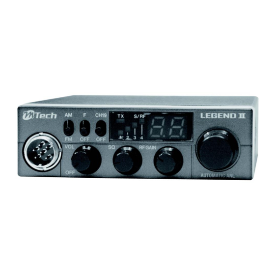
PARTS OF THE RADIO Front 1. AM/FM Select Switch Switches modulation mode AM or FM. 2. Config. Select Switch Switches config. select mode on or off. 3. CH19 Switch Switches the radio over to channel 19. 4. TX LED Indicates when the radio is transmitting. 5. -
Page 5: Back
Back 12. Antenna connector Connects to a male PL-259 external antenna cable (antenna sold separately). 13. External Speaker Jack See Connecting external speakers, below. 14. 12 Volt DC Power Cord 15. Fuse Holder Microphone 16. Push-to-talk (PTT) button INSTALLATION Connect the microphone Align the microphone connector with the jack on the front of the radio. -
Page 6: Connect The Power
Connect the power You can connect the radio to any standard 12 volt DC power source, with a negative ground. If you don’t know whether your power supply uses a positive or negative ground, consult the manual for your power supply or contact the manufacturer. -
Page 7: Connecting External Speakers
Your dealer can help you select the antenna that is best for your needs. Consult the specifications in the back of this manual for detailed transmitter and antenna information. Connecting external speakers Your radio supports a external speaker for remote monitoring features. External speakers are sold separately. -
Page 8: Maintenance
Adjusting the RF gain -Turn the knob clockwise to boost the reception of weak signals, or counter-clockwise to reduce the reception of strong signals. -In areas where strong signals cause noise and distortion, reduce the RF gain (turn the knob counter-clockwise). -In areas where weaker signals are difficult to hear, increase the RF gain (turn the knob clockwise). -
Page 10: Specifications
SPECIFICATIONS General Channels 40 AM/FM (Config. E) Frequency Range 26.965 to 27.405 MHz (Config. E) Frequency Control Phase Locked Loop (PLL) synthesizer Frequency Tolerance ±600Hz Operating Temperature -10ºC to +55ºC Microphone Electret condenser Type Microphone Input Voltage 13.2 V DC Current Drain TX full mod., 2.0A Max RX with max. -
Page 11: Channels And Frequencies
CHANNELS AND FREQUENCIES Freq. Freq. 26.965 MHz 27.215 MHz 26.975 MHz 27.225 MHz 26.985 MHz 27.255 MHz 27.005 MHz 27.235 MHz 27.015 MHz 27.245 MHz 27.025 MHz 27.265 MHz 27.035 MHz 27.275 MHz 27.055 MHz 27.285 MHz 27.065 MHz 27.295 MHz 27.075 MHz 27.305 MHz 27.085 MHz... -
Page 12: Norms
NORMS Config. code FM channel AM channel 40CH FM (4W) 40CH AM (4W) 26.965 to 27.405MHz 26.965 to 27.405MHz 80CH FM (4W) 80CH AM (1W) 26.565 to 27.405MHz 26.565 to 27.405MHz 40CH FM (4W) 40CH AM (1W) 26.965 to 27.405MHz 26.965 to 27.405MHz 40CH FM (4W) 40CH AM (1W) - Page 13 INSTRUCTIUNI DE UTILIZARE STATIE RADIO CB LEGEND II Bine ati venit in comunitatea utilizatorilor de statii radio in banda libera CB. Statia dvs este o unitate radio avansata destinata utilizarii in banda libera. Statia va opera pe oricare dintre cele 40 frecvente radio AM/FM.
- Page 14 Nota: Va trebui sa folositi o antena exterioara CB vanduta separat. DESCRIEREA PRODUSULUI Mufa pentru antena – se conecteaza antena printr-un conector tata PL-259 (antena se vinde separat). Jack pentru difuzor exterior Cablu de alimentare pentru 12V Suport pentru siguranta Microfon PTT –...
- Page 15 FATA STATIEI Switch selectie AM/FM – schimba modul de modulatie de la AM la FM. Switch pentru selectarea configuratiei – activeaza sau dezactiveaza meniul setarilor pe tari. Switch pentru canalul 19 – trece statia pe canalul 19. Led TX – este activ cand statia emite. Indicator S/RF (Semnal/RF) –...
- Page 16 pozitiva sau negativa adresati-va producatorului sau consultati manualul autovehiculului. ATENTIE! Nu alimentati statia la o sursa de energie daca nu sunteti sigur de tipul de impamantare al acesteia. 1. Asigurati-va ca sursa de alimentare este oprita. 2. Legati firul rosu de alimentare al statiei la polul pozitiv (+) al sursei de alimentare si conectati firul negru al statiei la polul negativ (-) al sursei de alimentare sau la o masa negativa (de exemplu caroseria masinii).
- Page 17 Urmati instructiunile de instalare furnizate de producator. Calibrati antena pe masina folosind un SWR metru: setati statia pe canaluil 20 si ridicati sau coborati spicul antenei in suport pana SWR-ul indicat este cat mai aproape de 1:1. ATENTIE! Asigurati-va ca SWR-ul este sub 2:1 inainte de a folosi statia.
- Page 18 Pentru a confirma setarea opriti si porniti alimentarea cu energie in mod repetat. Rotiti potentiometrul pentru selectarea canalelor in sensul acelor de ceasornic pentru a va deplasa in sus in cadrul listei de canale, rotiti-l in sensul invers acelor de ceasornic pentru a va deplasa in jos in lista de canale.
- Page 19 Instructiuni de intretinere La fiecare 6-12 luni va rugam sa verificati: SWR-ul sa fie sub 2:1 Toate conexiunile electrice sunt sigure si fara coroziuni ale cablurilor Cablul antenei nu are semne de imbatranire si nu este avariat. ...
- Page 20 Microfon Microfon cu condensator izolat Puterea de intrare 12 V Maxim 2 Amp in modul de transmisie Intensitatea curentului maxim 1.5A in modul de receptie consumat Putere consumata Maxim 24W Dimensiuni 115 x 180 x 35 mm Greutate 0.8 kg Tip conector pentru UHF, SO-239...
- Page 21 Distorsiuni Mai putin de 10%, 0.5W 1KHz Specificatiile si carecteristicile tehnice pot fi schimbate fara previz. LISTA CANALE SI FRECVENTE Canal Frecventa Canal Frecventa 26.965 MHz 27.215 MHz 26.975 MHz 27.225 MHz 26.985 MHz 27.255 MHz 27.005 MHz 27.235 MHz 27.015 MHz 27.245 MHz 27.025 MHz...
- Page 22 40 canale FM (4W) 40 canale FM (4W) de la 26.965 la 27.405 MHz de la 26.965 la 27.405 MHz 40 canale FM (4W) 80 canale FM (4W) de la 26.965 la 27.405 MHz de la 26.965 la 27.405 MHz 40 canale FM (4W) de la 26.965 la 27.405 MHz Pozitia AM(CEPT)
- Page 23 Disclaimer: In case of discrepancy in translation or interpretation of the manual contents, the English version shall prevail.
Need help?
Do you have a question about the Legend II and is the answer not in the manual?
Questions and answers