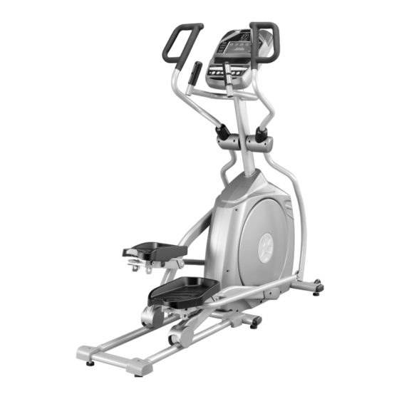
Spirit XE295 Owner's Manual
Spirit xe295 elliptical trainer
Hide thumbs
Also See for XE295:
- User manual (68 pages) ,
- Owner's manual (41 pages) ,
- Owner's manual (26 pages)

Related Manuals for Spirit XE295


Summary of Contents for Spirit XE295
-
Page 1: Elliptical Trainer
ELLIPTICAL TRAINER OWNER’S MANUAL PLEASE CAREFULLY READ THIS ENTIRE MANUAL BEFORE OPERATING YOUR ELLIPTICAL! -
Page 2: Table Of Contents
Table Of Contents Important Safety Instructions……………………………………………...3 Important Electrical Instructions…………………………………………..4 Important Operation Instructions………………………………………….4 Assembly Instructions…………………………………………....5 Product Features……………………………………………………….….11 Operation of Your Console……………..…………………………………13 Programmable Features…………………………………………………..16 Using A Heart Rate Transmitter…………………………………………..22 General Maintenance……………………………………………………... Exploded View Diagram…………………………………………….……..25 Parts List…………………………………………………………………….26 ATTENTION This elliptical is intended for residential use only and is warranted for this application. Any other application voids this warranty in its entirety. -
Page 3: Important Safety Instructions
Important Safety Instructions WARNING - Read all instructions before using this appliance. DANGER - To reduce the risk of electric shock disconnect your elliptical from the electrical outlet prior to cleaning and/or service work. WARNING - To reduce the risk of burns, fire, electric shock, or injury to persons, install the elliptical on a flat level surface with access to a 230-volt, 10-amp grounded outlet with only... -
Page 4: Important Electrical Instructions
Important Electrical Instructions WARNING! NEVER remove any cover without first disconnecting AC power. lf voltage varies by ten percent (10%) or more, the performance of your elliptical may be affected. Such conditions are not covered under your warranty. If you suspect the voltage is low, contact your local power company or a licensed electrician for proper testing. -
Page 5: Assembly Instructions
Assembly Instructions PRE-ASSEMBLY Using a razor knife (Box Cutter), cut the banding straps that wrap around the carton. Reach under the bottom edge of the carton and pull it away from the cardboard underneath, separating the staples that join the two together. Lift the box over the unit and unpack. - Page 6 STEP 1: Rail Assembly & Console Mast 1. Locate the Console Mast (12) and Console Mast Cover (72); slide the Cover onto the Mast as far as it will go. Make sure the Console Mast Cover (72) is facing the correct way. 2.
- Page 8 STEP 2: Connecting & Lower Swing Arms 1. Slide two Wave Washers (150) onto each side of the Swing Arm Axle. Slide the Lower Swing Arms (10 Left, 11 Right) onto the axles and secure with the two Hex Head Bolts (99) and Flat Washers (141).
- Page 9 STEP 3: Connecting Arm Slide the Rubber Sleeve (162) onto the left (16) and right (17) Upper Swing Arms. Make sure the wide part is at the bottom. Attach the wire (50) from the Right Upper Swing Arm (17) to the wire (49) that exits the Console Mast tube (12).
- Page 10 STEP 4: Plastic Parts 1. Fasten the two Wheel Covers (79) to the rollers with four Phillips Head Screws (115).Tighten with the Phillips Head Screw Driver (157). 2. Attach the left and right side cover (80) to the mid-stabilizer tube with two Phillips Head Screws (115).
-
Page 11: Product Features
Product Features Footpads The Foot pedals are adjustable to meet the user’s style of pedaling the elliptical. There are three positions available with a simple pull-pin adjustment located under the footpads (see illustration below).The lowest position will set the footpads at zero (0) degrees, or flat at the bottom of the elliptical stroke. - Page 12 Console MUSCLE ACTIVATION FIGURE There is an anatomical figure located at the top of the console. This figure will light all areas that are activated when using the elliptical trainer. These will light up during any of the programs. You can control which muscles are activated by changing up the pedal pattern or switching your hand position.
-
Page 13: Operation Of Your Console
Operation Of Your Console GETTING FAMILIAR WITH THE CONTROL PANEL Integrated Speakers for MP3 Player Muscle Activation Profile Large LCD with scrolling feedback and scrolling message center Heart Rate % Profile Swivel Fan to keep you cool Ten innovative programs offer a variety of work-outs Easy-Touch Convenient cargo... -
Page 14: Quick Start
Quick Start This is the quickest way to start a workout. After the console powers up you just press the Start key to begin, this will initiate the Quick Start mode. In Quick Start the Time will count up from zero and the workload may be adjusted manually by pressing the Level Up/Down buttons. - Page 15 Program Keys The Program Keys are used to preview each program. When you first turn the console on you may press each program key to preview what the program profile looks like. If you decide that you want to try a program, press the corresponding program key and then press the Enter key to select the program and enter into the data-setting mode.
-
Page 16: Programmable Features
Programmable Features MANUAL The Manual program works as the name implies, manually. This means that you control the workload and not the computer. To start the Manual program, follow the instructions below or just press the Manual button, then the Enter button and follow the directions in the Message Center. -
Page 17: Preset Programs
Preset Programs The elliptical has five different programs that have been designed for a variety of workouts. These five programs have factory preset work level profiles for achieving different goals. Hill RESISTANCE Resistance: This program follows a triangle or pyramid type of gradual progression from approximately 10% of maximum effort (the level that you chose before starting this program) up to a maximum effort which lasts for 10% of the total workout time,... - Page 18 Programming Preset Programs Select the desired program button then press the Enter key. The Message Center will ask you to enter your Age. You may adjust the age setting, using the Level Up/Down keys, then press the Enter key to accept the new number and proceed on to the next screen.
- Page 19 Custom User Defined Programs There are two customizable User programs that allow you to build and save your own workout. The two programs, User 1 and User 2, operate exactly the same way so there is no reason to describe them separately. You can build your own custom program by following the instructions below or you can save any other preset program you complete as a custom program.
- Page 20 Heart Rate Programs Before we get started, a word about Heart Rate: The old motto, “no pain, no gain”, is a myth that has been overpowered by the benefits of exercising comfortably. A great deal of this success has been promoted by the use of heart rate monitors.
-
Page 21: Rate Of Perceived Exertion
Rate Of Perceived Exertion Heart rate is important but listening to your body also has a lot of advantages. There are more variables involved in how hard you should workout than just heart rate. Your stress level, physical health, emotional health, temperature, humidity, the time of day, the last time you ate and what you ate, all contribute to the intensity at which you should workout. -
Page 22: Using A Heart Rate Transmitter
Using A Heart Rate Transmitter (OPTIONAL) How to wear your wireless chest strap transmitter: Attach the transmitter to the elastic strap using the locking parts. Adjust the strap as tightly as possible as long as the strap is not too tight to remain comfortable. - Page 23 Heart Rate Program Operation Note: You must wear the heart rate transmitter strap for these programs. Both programs operate the same, the only difference is that HR1 is set to 60% and HR2 is set to 80% of the maximum heart rate. They both are programmed the same way. To start an HRC program follow the instructions below or just select the HR1 or HR2 program, then the Enter button and follow the directions in the Message Center.
-
Page 24: General Maintenance
General Maintenance Wipe down all areas in the sweat path with a damp cloth after each workout. If a squeak, thump, clicking or rough feeling develops the main cause is most likely one of two reasons: The hardware was not sufficiently tightened during assembly. All bolts that were installed during assembly need to be tightened as much as possible. -
Page 25: Exploded View Diagram
Exploded View Diagram... -
Page 26: Parts List
Parts List DESCRIPTION O'TY Main Frame Rear Rail Assembly Console Holder Assembly Cross Bar Bushing Housing, Pedal Arm Pedal Arm (L) Pedal Arm (R) Connecting Arm (L) Connecting Arm (R) Lower Handle Bar (L) Lower Handle Bar (R) Console Mast Idler Wheel Assembly Crank Arbor Rail Assembly... - Page 27 DESCRIPTION O'TY 43~9 Fan Fixing Plate 43~10 LCD Transparent Piece 43~11 Console Speaker Cover (L) 43~12 Console Speaker Cover (R) 43~13 Fan Assembly 43~14 270m/m_W/Receiver, HR 43~15 Console Display Board 43~16 Key Board 43~17 Interface Board 43~18 Earphone socket with cable and securing metal 43~19 Amplifier Controller 43~20 250m/m_Speaker W/Cable 43~21 Speaker Grill Anchor...
- Page 28 DESCRIPTION O'TY Spacer Bushing Drive Pulley Oval End Cap Sensor Rack Handle Switch Bracket Woodruff Key 1/4" × 3/4"_Hex Head Bolt 5/16" × 15m/m_Hex Head Bolt 5/16" × 1-1/4"_Hex Head Bolt 3/8" × 3/4"_Hex Head Bolt 3/8" × 2-1/4"_Hex Head Bolt 3/8"...
- Page 29 DESCRIPTION O'TY 12/14m/m_Wrench (160m/m) 5/16" × 1-3/4"_Hex Head Bolt 5/16" × 23 × 1.5T_Curved Washer Switch Wire Cap Swing Arm Bushing Pedal Foam (L) Pedal Foam (R) Side Case Plate(L) Side Case Plate(R) Pedal Bushing 5/16" × 25 × 3T_Nylon Washer 5/16"...
Need help?
Do you have a question about the XE295 and is the answer not in the manual?
Questions and answers