Therma-Stor HI-E DRY 195 Installation, Operation And Maintenance Instructions
Hide thumbs
Also See for HI-E DRY 195:
Table of Contents
Advertisement
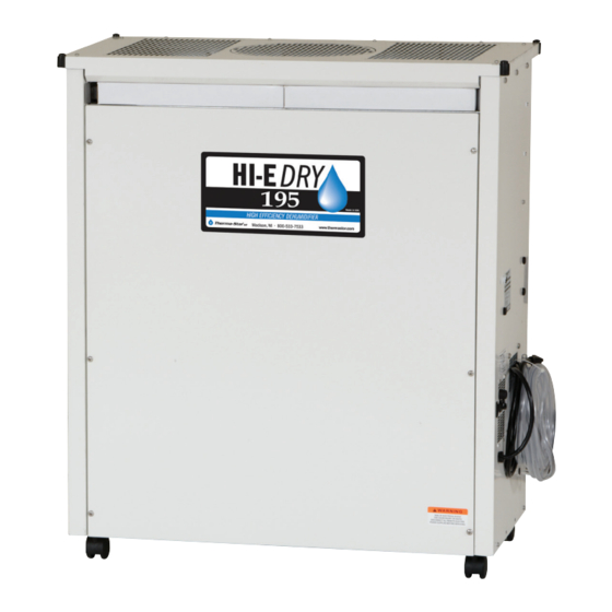
HI-E Dry 195
HI-E DRY 195
Installation, Operation and Maintenance Instructions
Installation, Operation and Maintenance Instructions
– Read and Save These Instructions –
– Read and Save These Instructions –
This manual is provided to acquaint you with
the dehumidifier so that installation, operation
and maintenance can proceed successfully.
Ultimate satisfaction depends on the quality
of installation and a thorough understanding
of this equipment. The dehumidifier is built
around tested engineering principles and has
passed a thorough inspection for quality of
workmanship and function.
HI-E Dry 195:
• Controlled by a dehumidistat with settings
from 20 to 80 percent relative humidity
and a positive "on" and "off" setting.
• Contains a blower switch that permits
continuous blower operation independent
of dehumidification.
• Portable and provided with four casters.
• Contains an internal condensate pump
capable of lifting condensate 17 feet and
20 feet of condensate hose.
• Wiring is through a factory installed six
foot power cord; 115 volt with ground.
• Environmentally friendly R410A refrigerant.
quest
quest
Specifications subject to change without notice.
Water Removal Rates (Pints/Day)
320 pints
245 pints
192 pints
205 pints
150 pints
162 pints
91 pints
81 pints
40 pints
4201 Lien Rd
Madison, WI 53704
www.QuestProtect.com
1
90˚F, 90%
80˚F, 80%
80˚F, 60% (AHAM)
70˚F, 80%
70˚F, 60%
60˚F, 80%
60˚F, 60%
50˚F, 80%
50˚F, 60%
Phone 608-237-8400
Toll-Free 1-800-533-7533
sales@QuestProtect.com
TS- 622
04/14
Advertisement
Table of Contents

Related Manuals for Therma-Stor HI-E DRY 195


Summary of Contents for Therma-Stor HI-E DRY 195
- Page 1 HI-E Dry 195 HI-E DRY 195 Installation, Operation and Maintenance Instructions Installation, Operation and Maintenance Instructions – Read and Save These Instructions – – Read and Save These Instructions – This manual is provided to acquaint you with the dehumidifier so that installation, operation and maintenance can proceed successfully.
-
Page 2: Table Of Contents
HI-E DRY 195 Installation, Operation and Maintenance Instructions Table of Contents Safety Precautions ............. 3 1. Specifications ..............4 2. Installation ................ 4 2.1 Location ..............4 2.1A In humid area, no ducting ......... 5 2.1B In humid area, duct inlet and/or outlet ....5 2.1C In remote area, duct inlet & outlet ..... 5 2.1D In remote area, duct outlet only ......5 2.1E In remote area, duct inlet only ......5 2.2 Electrical Requirements ..........5 2.3 Condensate Removal . -
Page 3: Safety Precautions
HI-E DRY 195 Installation, Operation and Maintenance Instructions Safety Precautions Read the installation, operation and maintenance instructions carefully before installing and using this unit. Proper adherence to these instructions is essential to obtain maximum benefit from your HI-E Dry 195 dehumidifier. READ AND SAVE THESE INSTRUCTIONS • It is designed to be installed INDOORS ONLY. • If used near a pool or spa, be certain there is NO chance the unit could roll into the water or be splashed and that it is plugged into a GROUND FAULT INTERRUPTER. • DO NOT use the HI-E Dry 195 as a bench or table. • Avoid discharging the air directly at people, especially in pool areas. quest quest quest quest 1-800-533-7533 www.QuestProtect.com Asset Protection and IAQ Solutions... -
Page 4: Specifications
HI-E DRY 195 Installation, Operation and Maintenance Instructions 1. Specifications Part Number 4030060 Power 115 VAC 12 amps Kilowatts 1.25 (80° 60%) Blower 540 CFM Capacity (24 hrs.) 192 pints (80°, 60%) Temp. Range 33°F–110°F Warranty 5 Year Limited Dimensions Unit Shipping Width 36.6” 39.25” Height 40” 48.75” Depth 19” 30” Weight 180 Lb 214 Lb Minimum Performance at Set Conditions Intake Air 70° 60%... -
Page 5: A In Humid Area, No Ducting
HI-E DRY 195 Installation, Operation and Maintenance Instructions 2.1A In Humid Area, No Ducting The simplest installation is to place the HI-E Dry 195 in the humid area with no ducting. The air inlet on top & outlet on the side must be at least 1’ from walls and other obstructions to air flow. 2.1B In Humid Area, Duct inlet and/or Outlet If the humid area is very large or has high ceilings, dehumidification can be improved by adding an inlet and/or outlet duct to circulate and destratify stagnant areas. For a large area, add inlet or outlet ducting to create flow across the area’s greatest length. For areas with ceilings higher than 12’, use an inlet duct to draw warm, moist air from near the ceiling. See section 2.4 for attaching duct collars & ducting. 2.1C In Remote Area, Duct Inlet & Outlet It is often desirable, especially in pool rooms and finished areas, to install the HI-E Dry 195 in an adjacent equipment room or unfinished area. Air is transferred between the humid room and the unit via ducting. The factory mounted humidity control on the HI-E Dry 195 cabinet may not sense the humidity in the humid room accurately enough with this installation method. If so, an additional humidity control can be mounted... -
Page 6: Condensate Removal
HI-E DRY 195 Installation, Operation and Maintenance Instructions 2.3 Condensate Removal The HI-E Dry 195 is equipped with an internal condensate pump to remove the water that is condensed during dehumidification. This allows the condensate to be pumped 20’ with the attached hose. If the condensate must be pumped more than 20 feet above the unit, a second pump must be added to relay the condensate. The condensate pump is mounted inside the HI-E Dry 195 as a permanent, integral part of the unit. It includes a safety switch feature that prevents flooding by turning off the HI-E Dry 195 if the pump fails. 2.4 Ducting 2.4A Optional Ducting Two twelve-inch collars are available as a kit from the factory that will allow ducting to be attached to the inlet and outlet of the HI-E Dry 195. Attach the inlet collar to the top of the unit by cutting the eight tabs that support the 12” round opening in the top. The 12” collar with three tabs can be attached via the holes provided in the front of the unit, and the other 12” collar can be affixed to the top opening. 2.4B Ducting for Dehumidification Ducting the HI-E Dry 195 as mentioned in sections 2.1B-2.1E requires consideration of the following points: Duct Sizing: For total duct lengths up to 25’, use a minimum 10” diameter round or equivalent rectangular. For longer lengths, use a minimum 12” diameter or equivalent. Grills or diffusers on the duct ends must not excessively restrict airflow. Isolated Areas: Effective dehumidification may require that ducting be branched to isolated, stagnant areas. Use 8” diameter branch ducting to each of two or three areas; use 6” to each of four or five areas; use 4” to each of six or more areas. 2.4C Ducting for Fresh Air Fresh air can be brought into the structure continuously by connecting a duct from outside to the HI-E Dry 195 inlet and by turning on the fan switch. Advantages of this form of ventilation include:... -
Page 7: Optional Remote Humidity Control
2.6 Hard Wiring the HI-E Dry 195 1. Remove the cabinet front to the left of the cord mount. 2. Cut the cord near the strain relief bushing and remove the cord and the strain relief bushing. 3. Trim and strip the wire ends for wire nuts. 4. Use a 1/2” connector to attach the hard wiring to the HI-E Dry 195. Use a minimum of #3-14 wire. Comply with all state and local code requirements. 5. Use wire nuts to attach the appropriate wire leads. Figure 1: Hard Wiring the HI-E Dry 195 3. Operation 3.1 Humidity Control Adjustment The dehumidifier will run continuously until the relative humidity (RH) is reduced to the humidity control dial setting. Setting the humidity control to lower RH levels will NOT increase the unit’s dehumidification rate, it will simply run longer to reduce the area’s RH to the setting. The HI-E Dry 195 100 unit (and refrigerant based dehumidifiers in general) will reduce a warm space’s RH to a lower level than that of a cool space. It is therefore pointless to set the humidity control to excessively low levels in cool rooms. Doing so will result in long periods of ineffective dehumidifier run time. -
Page 8: Defrost Control Adjustment
5. Service CAUTION: Servicing the HI-E Dry 195 with its high-pressure refrigerant system and high voltage circuitry presents a health hazard which could result in death, serious bodily injury, and/or property damage. Only qualified service people should service this unit. -
Page 9: Troubleshooting
The evaporator operates in a flooded condition, which means that it should always be full of liquid refrigerant during normal operation. A flooded evaporator should maintain constant pressure and temperature across the entire coil, from inlet to outlet. The mixture of gas and liquid refrigerant enter the accumulator after leaving the evaporator coil. The accumulator prevents any liquid refrigerant from reaching Figure 3: Refrigeration system of HI-E Dry 195 the compressor. The compressor evacuates the cool refrigerant gas from the accumulator and compresses it to a high pressure and temperature to repeat the process. 5.3 Troubleshooting No dehumidification, neither blower nor compressor run with fan switch OFF. 1. Unit unplugged or no power to outlet. 2. Humidity control set too high or defective (Sec. 3.1 & 5.9) 3. Loose connection in internal wiring. 4. Open low pressure control (Sec. 3.4 & 5.7) Some dehumidification, blower runs continuously but compressor only runs sporadically with fan switch OFF. -
Page 10: Refrigerant Charging
HI-E DRY 195 Installation, Operation and Maintenance Instructions 7. Bad connection in pump circuit (Fig. 4). 8. Pump float switch or safety switch open (Sec. 5.11). 9. Pump motor defective (Sec. 5.11). Blower does not run. Compressor runs briefly but cycles on & off. 1. Loose connection in blower circuit (Fig. 4). 2. Obstruction prevents impeller rotation. 3. Defective blower (Sec. 5.5). Unit removes some water but not as much as expected. -
Page 11: Blower Replacement
HI-E DRY 195 Installation, Operation and Maintenance Instructions 5.5 Blower Replacement The centrifugal blower has a PSC motor and internal thermal overload protection. If defective, the complete assembly must be replaced. 1. Unplug the power cord. 2. Remove the cabinet front (6 screws). 3. If an outlet duct is connected to the unit, remove it. 4. Disconnect the blower leads: white from the compressor run capacitor, and black connected to the fan switch. 5. Remove the nuts & bolts holding the blower outlet flange to the cabinet end and remove the blower. 6. Reassembling with the new blower is the above procedure reversed. 5.6 Compressor/Capacitor Replacement This compressor is equipped with a two terminal external overload, run capacitor, but no start capacitor or relay (see Fig. 4). CAUTION-ELECTRICAL SHOCK HAZARD: Electrical power must be present to perform some tests; these tests should be performed by a qualified service person. -
Page 12: B Replacing A Burned Out Compressor
HI-E DRY 195 Installation, Operation and Maintenance Instructions 10. Reconnect the wires to the compressor and capacitor; plug in and turn on the unit. If the compressor fails to start, replace the run capacitor. 11. If the unit still does not start, adding a hard-start kit will provide greater starting torque. If this does not work, the compressor has an internal mechanical defect and must be replaced. 5.6B Replacing a Burned Out Compressor The refrigerant and oil mixture in a compressor is chemically very stable under normal operating conditions. However, when an electrical short occurs in the compressor motor, the resulting high temperature arc causes a portion of the refrigerant oil mixture to break down into carbonaceous sludge, a very corrosive acid, and water. These contaminants must be carefully removed otherwise even small residues will attack replacement compressor motors and cause failures. The following procedure is effective only if the system is monitored after replacing the compressor to insure that the clean up was complete. 1. This procedure assumes that the previously listed compressor motor circuit tests revealed a shorted or open winding. If so, cautiously smell the refrigerant from the compressor service port for the acid odor of a burn out. WARNING: The gas could be toxic and highly acidic. If no acid odor is present, skip down to the section on changing a non-burn out compressor. -
Page 13: C Replacing A Compressor
HI-E DRY 195 Installation, Operation and Maintenance Instructions NOTE: NEVER use the compressor to evacuate the system or any part of it. 5.6C Replacing a Compressor- Non-Burn Out Remove the refrigerant from the system. Replace the compressor and liquid line filter/drier. Charge the system to 50 PSIG and check for leaks. Remove the charge and weigh in the refrigerant quantity listed on the nameplate. Operate the system to verify performance. 5.7 Relay The contacts of the single pole, single throw relay complete the power circuit to the compressor. The contacts are closed when power is provided to the relay coil via the control circuit. The control circuit includes the humidity control, low pressure control, defrost thermostat and timer. 5.8 Humidity Control The humidity control is an adjustable switch that closes when the relative humidity of the air in which it is located rises to the dial set point. It opens when the RH drops 4 to 6% below the set point. -
Page 14: Wiring Schematic
MOTOR RELAY CAPACITOR COMPRESSOR PART NO. REV. Made in U.S.A. 4023609 Therma-Stor LLC, Madison, WI 800-533-7533 or Local 608-222-5301 www.thermastor.com Figure 4: Electrical Schematic of HI-E Dry 195 quest quest quest quest 1-800-533-7533 www.QuestProtect.com Asset Protection and IAQ Solutions sales@QuestProtect.com... -
Page 15: Service Parts List
HI-E DRY 195 Installation, Operation and Maintenance Instructions 7. Service Parts: HI-E Dry 195 Dehumidifier ITEM PART NO. QTY. DESCRIPTION 4021083 Blower with Capacitor 4033032-06 1 Capacitor, Run, 50MFD, 370v 4021589 Capillary Tubes 4023604 Caster, 2”, Plastic, Swivel 4028246 Coil, Condenser 4028245-02 1 Coil, Evaporator E-Coat 4030131 Compressor 4030121 Compressor Overload 4023649 Condensate Pump... -
Page 16: Accessories
HI-E DRY 195 Installation, Operation and Maintenance Instructions ACCESSORIES: HI-E Dry 195 Dehumidifier PART NO. DESCRIPTION 4023684 Duct Collar Kit 4020175 Humidity Controller 4021799 Filter (2 Required) 4024750 12” x 25’ Flex Duct quest quest quest quest 1-800-533-7533 www.QuestProtect.com Asset Protection and IAQ Solutions sales@QuestProtect.com... -
Page 17: Warranty
HI-E Dry 195 Installation, Operation and Maintenance Instructions HI-E DRY 195 Installation, Operation and Maintenance Instructions HI-E Dry 195 Dehumidifier Limited Warranty Warrantor: Therma-Stor LLC 4201 Lien Rd Madison, WI 53704 Telephone: 1-800-533-7533 Who Is Covered: This warranty extends only to the original end-user of the HI-E Dry 195 dehumidifier, and may not be assigned or transferred. Year One: Therma-Stor warrants that, for one (1) year the HI-E Dry 195 dehumidifier will operate free from any defects in materials and workmanship, or Therma-Stor will, at its option, repair or replace the defective part(s), free of any charge. Year(s) Two Through Five: Therma-Stor further warrants that for a period of five (5) years, the condenser, evaporator, and compressor of the HI-E Dry 195 dehumidifier will operate free of any defects in material or workmanship, or Therma-Stor, at its option, will repair or replace the defective part(s), provided that all labor and transportation charges for the part(s) shall be borne by the end-user.
Need help?
Do you have a question about the HI-E DRY 195 and is the answer not in the manual?
Questions and answers