Table of Contents
Advertisement
Quick Links
Advertisement
Table of Contents

Related Manuals for Benassi BL 6000


Summary of Contents for Benassi BL 6000
- Page 1 SpA INSTRUCTION MANUAL TILLER BL 6000 19/04/2011 ...
-
Page 2: Table Of Contents
CE MARK ................. 3 SERVICING................. 7 TILLING UNITS ................ 3 CLUTCH BELT ................. 7 DIMENSIONS ................ 4 WARRANTY................ 8 PACKING AND TRANSPORT…………………………………………………... 4 STICKERS FOR INSTRUCTION AND SAFETY ....... 4 INTRODUCTION • Dear user, we thank you for preferring a BENASSI product. • We are confident that the top performance and the easy use of our machine will satisfy you. • This machine is the result of a long experience working at the top quality standard and using first quality material. • Carefully using and servicing this machine, you will certainly get satisfactory performances for a long time. • Please read very carefully this booklet before using your tiller. • Pay special attention to the instructions marked out by the following sign: ATTENTION ... -
Page 3: Key To Machine Parts
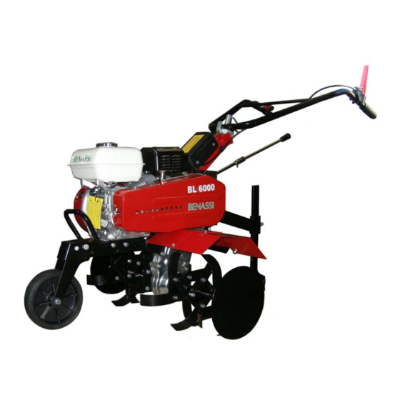
BL 6000 KEY TO MACHINE PARTS HONDA KIPOR 1‐ Transport wheel 2‐ Engine oil cap 3‐ Tillers 4‐ Tiller protection 5‐ Braking spur 6‐ Belt cover 7‐ Gear lever 6 8‐ Clutch lever 13 15 9‐ Throttle lever 10‐ Handlebar adjustment 11‐ Fuel tank cap 12‐ Handle 13‐ Recoil starter 14‐ Choke lever 15‐ Air cleaner ... -
Page 4: Dimensions
The small wheel holder is fitted to the frame by means of a screw nut and a splint pin. • Fit the two guard‐extensions to the main tiller protections fitted on the body of the machine using the proper screws and nuts. The protection guards should reach a width of 60 cm according to the CE requirements. • During the transport the handle can be left unassembled by means of the threaded bush that fix it to the handlebar support. The tiller is equipped with a front handle (see Pict.4 Ref. ”A”) in order to be able to lift and to transport the machine easily. STICKERS FOR INSTRUCTION AND SAFETY Please find here below the stickers put on the machine. It is very important that they are always clearly legible to prevent any accident. 2) 1) BL 6000 4) 5) R· 2· 0· 1 7) In case the stickers are damaged it is absolutely necessary to replace them by ordering the original spare parts. ... -
Page 5: Starting And Stopping
BL 6000 STARTING AND STOPPING Whenever you are starting the engine of the machine, follow these instructions very carefully: • Check the engine oil level: A BRAND NEW MACHINE IS DELIVERED WITHOUT OIL IN THE ENGINE, THEREFORE YOU SHOULD FILL IT UP TO THE LEVEL ON THE DIP STICK OF THE OIL CUP. • Please read carefully on the booklet the ENGINE USE AND MAINTENANCE concerning the “operations before starting”. • Start the engine only in open spaces. CLUTCH LEVER PROVIDED WITH SAFETY DEVICE (see picture 6b) • Lever (“A”) pulled: to get the lever working release the safety device (“B”), now the clutch is engaged (the tiller moves forward or backwards depending on the engaged gear) • Lever (“B”) released: clutch lever disengaged (the tiller stops). Pull the choke lever (Pict.5 Ref. “A”). Turn the throttle lever to the “MAX” position (Pict. 6a Ref. “A”). The switch (Ref. “A” Pict.6a) must be “ON”. The clutch lever (Pict. 6b Position “A”) must be disengaged. Pull the starting rope by the handle (Pict. 5 Ref. “B”), firstly smoothly and then strongly: when you feel some resistance don’t lea‐ ve the handle but help the recoiling of the rope with your hand. When the engine runs move the choke lever to the initial position and the throttle lever in the mid‐position (Pict. 6a Ref. “B”). To stop the engine move the switch to the “OFF” position (Fig.6a Ref.”A”). HONDA KIPOR Pict. 5 A B B Pict. 6 ... -
Page 6: Use And Adjustment
BL 6000 USE AND ADJUSTMENT • The tiller is equipped with a mechanical transmission that allows two forward speeds and one reverse. • When the machine is standstill to move forward simply engage the gear lever (Pict.7 Ref. “A”) in the first or in the second speed (Pict.7 Ref. “B”) and then press down completely the lever (Pict.6b Ref. “A”) to start the movement. • When the machine is standstill to move backwards engage the gear lever (Pict.7 Ref. “A”) in the position “R” (Pict.7 Ref. “B”) and then press down completely the lever (Pict.6b Ref. “A”) to start the movement. • The clutch cable must be adjusted in a way that allows the belt to be put under tension when the lever is situated at about 1 cm from the knob. To this purpose you have to regulate the register of the cable next to the lever (Ref. “B” Pict.6). • When the lever (Pict.6b Ref. “A”) is released the machine stops immediately while the engine is running. • The handlebar can be adjusted by unscrewing the blocking lever (Pict.6 Ref. “C”). Adjust the handlebar in the desired position and then lock it again. • The tiller is 80 cm wide, it is composed by 3 knives + protection plate on both sides. It can be reduced to 60 cm by removing one blade from each sides (see picture 2). • The sharp side of the blades must be turned towards the front side of the machine. • We recommend to use the tiller with the side plates because they improve the stability of the machine while working. • The machine can fit an adjustable ridger which is an optional accessory delivered complete with its own support which should be fitted on the handlebar holder replacing the standard spur and using the same bolt. CAUTION: IT IS ADVICED NOT TO KEEP THE MOTOR RUNNING WHEN THE MACHINE IS NOT BEING USED FOR ITS SPECIFICAL PURPOSE. B Pict. 7 SPUR ADJUSTMENT To get an optimal tilling work and a right advancement of the tiller adjust the spur as shown in picture 8, this adjustment has to be done on both sides of the machine: − Adjustment for hard soils: loosen nut and screw (A) and lift the spur as to shift back the weight of the machine. ... -
Page 7: Servicing
BL 6000 SERVICING For the usual engine servicing (oil, filter, spark plug and adjustments) read the engine manual delivered with the machine. • It is necessary to check periodically the oil level in the gearbox by at least every 50 working hours. If necessary add MPS SAE 80/90 oil. • The oil has to be changed every 200 working hours. Unscrew the cap (Ref. “B” Pict.10), drain out all the oil letting the cap (Ref. “A” Pict.10) open. Then put back the cap (Ref. “B” Pict.19) and top up with oil (about 1,3 litres). • The frame has waterproof ball bearings. The transmission in the frame is engaged by two normal grease‐lubricated chains. • All the joints, the cables and the tightener support bolt should be oiled from time to time. • Keep the machine and the blades clean. Check periodically, at least once a year, that all the screws and nuts are well tied, especially the screws of the tiller (always wear protection gloves while working on the tiller). ... -
Page 8: Warranty
S.p.A. VIA LAMPEDUSA 1 40017 S. MATTEO DELLA DECIMA (BO) ‐ ITALY TEL. +39/051/820511 TELEFAX +39/051/6826164 e‐mail: export@benassispa.it web: www.benassi.eu ...
Need help?
Do you have a question about the BL 6000 and is the answer not in the manual?
Questions and answers