Table of Contents
Advertisement
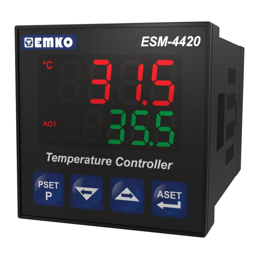
ESM-4420 48 x 48 DIN 1/16
Temperature Controller with Universal Input
- 4 digits process(PV) and 4 digits process set value
(SV) display
- Universal process input (TC, RTD )
- Configurable ON/OFF, P, PI, PD and PID control forms
- Adaptation of PID Coefficients to the system with Self-Tune
operation (Step Response Tuning)
- Programmable Heating or Cooling Functions for Control Output
- Alarm Functions for Alarm Output
Instruction Manual. ENG ESM-4420 02 V03 04/08
Advertisement
Table of Contents

Related Manuals for EMKO ESM-4420


Summary of Contents for EMKO ESM-4420
- Page 1 - Configurable ON/OFF, P, PI, PD and PID control forms - Adaptation of PID Coefficients to the system with Self-Tune operation (Step Response Tuning) - Programmable Heating or Cooling Functions for Control Output - Alarm Functions for Alarm Output Instruction Manual. ENG ESM-4420 02 V03 04/08...
- Page 2 ABOUT INSTRUCTION MANUAL Instruction manual of ESM-4420 Temperature Controller consists of two main sections. Explanation of these sections are below. Also, there are other sections which include order information and technical specifications of the device. All titles and page numbers in instruction manual are in “...
-
Page 3: Table Of Contents
3.4 SUPPLY VOLTAGE INPUT CONNECTION OF THE DEVICE 3.5 PROCESS INPUT CONNECTION 3.5.1 TC (THERMOCOUPLE) CONNECTION 3.5.2 RTD CONNECTION 3.6 GALVANIC ISOLATION TEST VALUES OF ESM-4420 TEMPERATURE CONTROLLER 4.OUTPUT CONNECTION FORMS IN ESM-4420 TEMPERATURE CONTROLLER......Page 4.1 PROCESS OUTPUT ( RELAY ) CONNECTION 4.2 PROCESS OUTPUT ( SSR DRIVER ) CONNECTION... - Page 4 EU DECLARATION OF CONFORMITY Manufacturer Company Name : Emko Elektronik A.S. Manufacturer Company Address: DOSAB, Karanfil Sokak, No:6, 16369 Bursa, Turkiye The manufacturer hereby declares that the product conforms to the following standards and conditions. Product Name : Temperature Controller...
-
Page 5: General Specifications
1.Preface ESM-4420 series temperature controllers are designed for measuring and controlling a process value. They can be used in many applications with their universal process input, control outputs and selectable alarm functions. Some application fields which they are used are below:... -
Page 6: Ordering Information
1.2 Ordering Information All order information of FG HI ESM-4420 E S M - 4 4 2 0 Te m p e r a t u r e (48x48 DIN 1/16) Controller are given on the table at left. User may form appropriate... -
Page 7: Warranty
1.3 Warranty EMKO Elektronik warrants that the equipment delivered is free from defects in material and workmanship. This warranty is provided for a period of two years. The warranty period starts from the delivery date. This warranty is in force if duty and responsibilities which are determined in warranty document and instruction manual performs by the customer completely. -
Page 8: Installation
2.Installation Before beginning installation of this product, please read the instruction manual and warnings below carefully. In package , - One piece unit - Two pieces mounting clamp - One piece instruction manual A visual inspection of this product for possible damage occured during shipment is recommended before installation. -
Page 9: General Description
Ip65 protection Panel surface NEMA 4X (maximum thickness 5mm / 0.2 inch) 2.2 Dimensions Maximum 5 mm / 0.2 inch ESM-4420 °C °F Temperature Controller PSET ASET 48 mm/ 1.89 inch 11 ± 1 mm /0.43 inch 84 mm / 3.31 inch... -
Page 10: Panel Cut-Out
2.3 Panel Cut-Out 65 mm / 2.56 inch (min) 46 mm / 1.81 inch (min) -
Page 11: Environmental Ratings
2.4 Environmental Ratings Operating Conditions Operating Temperature 0 to 50 °C Max. Operating Humidity : Rh (non-condensing) Altitude Up to 2000m. Forbidden Conditions: Corrosive atmosphere Explosive atmosphere Home applications (The unit is only for industrial applications) 2.5 Panel Mounting 1-Before mounting the device in your panel, make sure that the cut-out is of the right size. -
Page 12: Installation Fixing Clamp
2.6 Installation Fixing Clamp The unit is designed for panel mounting. 1-Insert the unit in the panel cut-out from the front side. 2- Insert the mounting clamps to the holes that located top and bottom sides of device and screw up the fixing screws until the unit completely immobile within the panel Montage of the unit to a system must be done with it’s own fixing clamps. -
Page 13: Electrial Wirings
3.Electrical Wirings You must ensure that the device is correctly configured for your application. Incorrect configuration could result in damage to the process being controlled, and/or personal injury. It is your responsibility, as the installer, to ensure that the configuration is correct. Parameters of the device has factory default values. -
Page 14: Electrical Wiring Diagram
3.2 Electrical Wiring Diagram Electrical wiring of the device must be the same as ‘Electrical Wiring Diagram’ below to prevent damage to the process being controlled and personnel injury. Universal Temperature Measurement Input (TC, RTD) Pt-100 P/N : ESM- CAT II PROCESS OUT ALARM OUT 5A@250V V... -
Page 15: View Of The Device Label
3.3 View of the Device Label 5A@250VV 230V ±15% 5A@250VV 50/60Hz 3VA PROCESS OUT ALARM OUT P/N : ESM-4420 Pt-100 CAT II... -
Page 16: Supply Voltage Input Connection Of The Device
3.4 Supply Voltage Input Connection of the Device Connection of Supply Voltage Input External Fuse (1 A Power Supply Switch Supply Voltage 230 V (± 15%) 50/60 Hz or 115 V (± 15%) 50/60 Hz or 24 V (± 15%) 50/60 Hz ( - 15%;+10% ) 50/60Hz Note-1: External fuse is recommended. -
Page 17: Process Input Connection
3.5 Process Input Connection 3.5.1 TC (Thermocouple) Connection Connect the wires with the polarity as shown in the figure left. Always use compensation wire corresponding to the thermocouple used. If present, the shield must be connected to a proper ground. Input resistance is greater than 10M W. -
Page 18: Galvanic Isolation Test Values Of Esm-4420 Temperature Controller
3.6 Galvanic Isolation Test Values of ESM-4420 Temperature Controller 2000 ESM-4420 .5..( For ESM-4420.3..) Ground Supply Voltage 2000V V 2000V V Process Output (Relay) 2000V V Process Output (SSR Driver) 2000V V 2000V V Alarm Output (Relay) 2000V V... -
Page 19: Output Connection Forms In Esm-4420 Temperature Controller
4. Output Connection Forms in ESM- 4420 Temperature Controller 4.1 Process Output ( Relay ) Connection Device T Fuse Last Control Element (Contactor) Fuse Load Fuses must be selected according to the application. 4.2 Process Output ( SSR Driver ) Connection Device Last Control Element... -
Page 20: Alarm Output ( Relay ) Connection
4.3 Alarm Output ( Relay ) Connection Device T Fuse Last Control Element (Contactor) Fuse Load Fuses must be selected according to the application. -
Page 21: Front Panel Definition And Accessing To The Menus
5. Front Panel Definition and Accessing to the Menus 5.1 Front Panel Definition LED indication of °C:Centigrade Unit LED indication of °F Fahrenheit Unit ESM-4420 Displays Process Output Status Led °C Process Value (PV) °F and Parameter Displays Set Value... -
Page 22: Run The Device And Observation Of Software Revision On The Displays
5.2 Run the Device and Observation of Software Version on the Displays When the power is applied to the device all led indicators and display segments are momentarily illuminated for testing. Software revision number of the controller on the bottom display is momentarily illuminated. ESM-4420 °C °F Temperature Controller Þ... -
Page 23: Adjustment Of Process Set Value
5.3 Adjustment of Process SET Value Operation Process °C °C °C °F °F °F Screen Set Screen PSET ASET PSET ASET PSET ASET When PSET button is pressed, PS Change the process set led starts to blink, the information to value with increment and indicate which set is shown is on top decrement buttons. -
Page 24: Parameters
6. Parameters 6.1 Parameter List Process menu title Process input type selection ( Default Value = J Type (FE.C.n) ) J type (Fe,Cu,Ni) Thermocouple, -200°C,900°C -328°F,1652°F K type (Ni,Cr,Ni) Thermocouple , -200°C,1300°C or -328°F,2372°F R type (Pt13%RhPt) Thermocouple , 0°C,1700°C or 32°F,3092°F S type (Pt10%RhPt) Thermocouple, 0°C,1700°C or 32°F,3092°F T type (Cu,Cu,Ni) Thermocouple , -200°C,400°C or -328°F,752°F Pt - 100 , -200°C,650°C or -328°F,1202°F... - Page 25 Proportional Band . It can be adjusted from 1.0% to 100.0%. ( Default Value = 10.0 ) If process control type selection CntS = Pýd , then this parameter can be observed Integral Time. It can be adjusted from 0 to 3600 secs. If process control type selection CntS = Pýd , then this parameter can be observed...
-
Page 26: Easy Access Diagram Of Parameters
Easy Access Diagram of Parameters Main Operation Password Entering Screen Screen After 5secs °C °C °C °C °C °F °F °F °F °F ASET PSET PSET ASET Press ASET/OK For entering to the Password entering Enter the password with button for entering programming section, press screen is shown when increment or decrement... -
Page 27: Entering To The Programming Section And Process Menu
6.3 Entering to the Programming Section and Process Menu Operation °C °C °C °F °F °F Screen PSET ASET PSET ASET PSET ASET Programming When 5secs is expired, Press PSET/P button for 5 Section Entering programming section seconds for entering Screen entering screen is shown. - Page 28 Process Input Type Selection °C °F Process Input Type can be changed into any of the type which are listed below with increment and decrement buttons. : J type (Fe,Cu,Ni) Thermocouple, -200°C,900°C -328°F,1652°F : K type (Ni,Cr,Ni)Thermocouple , -200°C,1300°C or -328°F,2372°F : R type (Pt13%RhPt) Thermocouple, 0°C,1700°C or 32°F,3092°F PSET...
- Page 29 Process Value Display Offset °C °F It can be adjusted -10% of scale ( PuPL- PLoL ) to 10% of scale ( PuPL- PLoL ) Defined value is added to the process display value. Press ASET/OK button for saving the changes and accessing to the PSET ASET following parameter.
- Page 30 6.4 Control Menu Operation °C °C °C °F °F °F Screen PSET ASET PSET ASET PSET ASET Programming When 5secs is expired, Press PSET/P button for 5 Section programming section seconds for entering Entering entering screen is shown. programming section Screen Press ASET/OK button for accessing to the password entering screen.
- Page 31 Process Type Selection °C °F Process Type Selection can be selected with increment and decrement buttons. Press ASET/OK button for saving the parameter and accessing to the next PSET ASET parameter. Process Control Type Selection °C °C Process Control Type can be °F °F selected...
-
Page 32: Alarm Menu
Integral Time °C °F It can be adjusted from 0 to 3600 seconds with increment and decrement buttons.If Process Control Type selection , then this parameter can be observed. Press ASET/OK button to save the value and access to the next PSET ASET parameter. -
Page 33: Protection Menu
6.5 Alarm Menu Operation °C °C °C °F °F °F Screen PSET ASET PSET ASET PSET ASET Programming When 5secs is expired, Press PSET/P button for 5 Section programming section seconds for entering Entering entering screen is shown. programming section Screen Press ASET/OK button for accessing to the password entering screen. - Page 34 Alarm Menu °C °F Press ASET/OK button for accessing to the alarm menu. PSET ASET Alarm Hysteresis value °C °F It can be adjusted from 0% of ( AuPL- ALoL ) to 50% of ( AuPL- ALoL ). Press ASET/OK button for saving the changes and accessing to the PSET ASET following parameter.
- Page 35 Alarm Set High Limit Value °C °F Maximum value of alarm set is defined with this parameter. It can be adjusted from alarm set low limit parameter to process set high limit parameter . It changes according to process input type and scale.
- Page 36 6.6 Protection Menu Operation °C °C °C °F °F °F Screen PSET ASET PSET ASET PSET ASET Programming When 5secs is expired, Press PSET/P button for 5 Section programming section seconds for entering Entering entering screen is shown. programming section Screen Press ASET/OK button for accessing to the password entering screen.
-
Page 37: Programming Section Entering Password
All menus and parameters except protection menu ( ) can be observed the parameter but they can not be changed. and exiting from (Please refer to Section 8. Failure Messages in ESM-4420 Temperature protection menu Controller(4)) parameters. Alarm Menu Protection Menu Process Menu °C... -
Page 38: General Information
7. General Information 7.1 Tune Operation Esm-XX20 devices use Self Tune (Step Response Tuning) method to automatically determine PID parameters. Starting the Tune operation by the user Enter to the programming section Select the parameter in menu, and turn to main operation screen. Observe that is blinking in set display Operation... - Page 39 Process Control Type Selection Process °C °C °C °F °F °F Type Selection PSET ASET PSET ASET PSET ASET P r e s s A S E T / O K Press ASET/OK button for button for saving the Change Process Control saving the parameter and p a r a m e t e r a n d...
-
Page 40: Process Output
If power is off while Self Tune operation continues, PID parameters and parameter are not changed. When power is off and then on, device starts to complete the Self Tune operation. If heating function and PID control form is selected for the system; If set value is greater than process value, process output becomes active till to the Temperature+[(Set - Temperature) / 2] value. -
Page 41: Alarm Types
7.2 Alarm Types Alarm types which are explained in Section 6.5 Alarm Types Selection parameter explained below: Process High Alarm °C °F Alarm Output PSET ASET Process Value Process Low Alarm °C °F Alarm Output PSET ASET Process Value Deviation High Alarm °C °F Alarm... - Page 42 Deviation Band Alarm °C °F Alarm Output PSET ASET Process Value Deviation Range Alarm °C °F Alarm Output PSET ASET Process Value...
-
Page 43: Failure Messages In Esm-4420 Temperature Controller
8. Failure Messages in ESM- 4420 Temperature Controller 1- Sensor failure in analog inputs. Sensor connection is wrong or there is no °C °F sensor connection. PSET ASET 2- If value that is read from the analog input is lower °C °C °F... -
Page 44: Specifications
9. Specifications Device Type : Temperature Controller Housing&Mounting : 48mm x 48mm x 95mm 1/16 DIN 43700 plastic housing for panel mounting. Panel cut-out is 46x46mm. Protection Class : NEMA 4X (IP65 at front, IP20 at rear). Weight : Approximately 0.22 Kg. Environmental Ratings : Standard, indoor at an altitude of less than 2000 meters with none condensing humidity.
Need help?
Do you have a question about the ESM-4420 and is the answer not in the manual?
Questions and answers