Table of Contents
Advertisement
Quick Links
Installation and Servicing
Hideaway 120
G.C. No. 41 313 29
Open Flue Boiler
This is a Cat I
Reference in these instructions to British Standards and Statutory
Regulations/Requirements apply only to the United Kingdom.
For Ireland the rules in force must be used.
The instructions consist of three parts, User, Installation and Servicing Instructions, which includes the Guarantee Registration
Card. The instructions are an integral part of the appliance and must, to comply with the current issue of the Gas Safety
(Installation and Use) Regulations, be handed to the user on completion of the installation.
Glow-worm appliances' are manufactured to the very highest standard so we are pleased
In the center pages are to be found your Guarantee Registration Card, which we recommend you complete and
If this card is missing you can obtain a copy or record your registration by telephoning the Heatcall Customer
Our Guarantee gives you peace of mind plus valuable protection against breakdown by covering the cost of:
All replacement parts
All labour charges
All call-out charges
One Contact Local Service
Instructions for Use
T o b e l e f t w i t h t h e u s e r
BS 6332
BS 5258
Appliance
2H
Guarantee Registration
Thank you for installing a new Glow-worm appliance in your home.
to offer our customers' a Comprehensive First Year Guarantee.
return as soon as possible.
Service number 01773 828100.
REGISTER YOUR GLOW-WORM APPLIANCE
FOR 1ST YEAR GUARANTEE PROTECTION
CALL 0208 247 9857
Customer Services:
Tel: (01773) 828100
Fax: (01773) 828070
Hepworth Heating Ltd.,
Nottingham Road, Belper, Derbyshire. DE56 1JT
General/Sales enquiries:
Tel: (01773) 824141 Fax: (01773) 820569
221758A.10.00
Advertisement
Table of Contents

Related Manuals for Glow-worm Hideaway 120


Summary of Contents for Glow-worm Hideaway 120
-
Page 1: Instructions For Use
Guarantee Registration Thank you for installing a new Glow-worm appliance in your home. Glow-worm appliances' are manufactured to the very highest standard so we are pleased to offer our customers' a Comprehensive First Year Guarantee. In the center pages are to be found your Guarantee Registration Card, which we recommend you complete and return as soon as possible. -
Page 2: Important Information
Under Section 6 of The Health and Safety at Work Act 1974, we Glow-worm Hideaways’ are central heating boilers, to provide are required to provide information on substances hazardous to heating and if required an indirect domestic hot water supply. - Page 3 Instructions for Use Warning Make sure that nothing obstructs the rear side grilles or FLUE BLOCKAGE clearances. See diagram 1.2 and 1.3 for minimum clearances. SAFETY DEVICE THERMOSTAT RESET BUTTON Boilers Installed in a Compartment CONTROL If the boiler is fitted in a compartment, cupboard etc., do not KNOB 'B' obstruct the purpose built compartment vents or grille on the PIEZO...
- Page 4 Instructions for Use Safety Device To Turn the Boiler Off This appliance is fitted with a flue blockage safety device which For short periods. Turn the boiler thermostat control knob “B” will shut down the appliance in the event of abnormal flue anticlockwise to “O”.
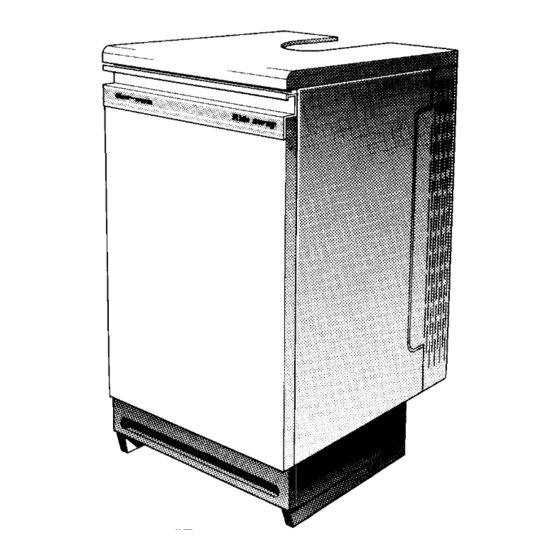
- Page 5 GENERAL DIMENSIONS - given in millimetres (Approx. inches) Diagram 1.1 445 121 Sheet Metal Parts HIDEAWAY 120 Warning. When installing or servicing this boiler care should be taken when handling sheet metal parts, to avoid the possibility medium RANGE RATING of personal injury.
- Page 6 1 General 1.4 B.S.I. Certification A compartment used to enclose the boiler must be designed and constructed specifically for this purpose. An existing This boiler is certificated by B.S.I. for safety and performance. cupboard or compartment modified for the purpose may be It is, therefore, important that no alteration is made to the boiler used.
-
Page 7: Water Systems
2 Water Systems 2.1 Water Pressure Head REFER TO BS 5546 This boiler must not be connected to a sealed water system. 22mm VENT 15mm COLD FEED This boiler shall only be connected to an open vented cistern water supply, with a minimum head of 1metre (39in) and a maximum of 27metre (90ft). -
Page 8: Flue And Ventilation 3
This safety device MUST NOT under any circumstances be ventilation. interferred with or put out of action. The safety device must only be replaced with the Glow-worm parts. The air vents must have minimum areas in accordance with “Compartment Air Vent B”. The figures quoted refer to the 3.1 Flue... -
Page 9: Installation 4
4 Installation Before fitting the boiler make sure the location selected is in CAPTIVE CASING accordance with the requirements of Section 1.7. BRACKET 4.1 Unpacking The boiler casing panels are packed separately within the main case. They are designed to enable the gas and water connections to be made before fitting the casing panels. - Page 10 4 Installation Fit the distributor tube, see diagram 4.2 or 4.4 for location, see diagram 4.3 for alignment. Fit appropriate fittings and plugs into THERMOSTAT the boiler connections. CAPILLARY IMPORTANT. Do not route any pipe across the front of the LOCATION boiler thermostat pocket, the controls, burner supply pipe, WASHER...
-
Page 11: Casing Location 5
5 Casing Location / Fitting 5.1 Side Vent Grille No. 8 One vent grille is supplied with the boiler which can be fitted at the rear of the left or right hand side casing. The grille is fitted SCREW (2) on the opposite side to any pipework connections. -
Page 12: Electrical Wiring
6 Electrical Wiring 6.1 Control Box Cable Connection COVER Remove the screw and cover from the mains inlet connector, see diagram 6.1. Using heat resistant flexible cable of suitable length and rating, as Section 1.6, connect the cable to the terminals in the connector. -
Page 13: Commissioning 7
7 Commissioning = OFF = PILOT/IGNITION = MAIN BURNER SETTING SETTING POINT POINT (Shown (Shown open) closed) A. GAS CONTROL KNOB J. PHIAL POCKET B. THERMOSTAT CONTROL K. GAS SERVICE COCK C. PIEZO IGNITION BUTTON L. DATA BADGE E. VIEWING WINDOW M. - Page 14 7 Commissioning Hideaway 120 - 4.4 to 5.2m /h 125 to 148ft FLAME 13 ( in.) These figures are for guidance only. DIMENSION APPROX. Stick the self adhesive arrow indicator, from the loose items pack, to the data label against the rating the boiler is set to.
-
Page 15: Servicing 8
8 Servicing Servicing must be carried out by a competent person. MAINS INLET Before starting any servicing, turn off the gas and electrical SERVICE CONNECTOR supply to the boiler. COCK (pull downwards) Always test for gas soundness after completing any servicing (turn off) or replacement of gas carrying components. - Page 16 8 Servicing 8.3 Burners and Injectors COMBUSTION MAIN Follow instructions to remove the cover, burner and controls CHAMBER BURNER (2) assembly as described in Section 8.2. COVER Remove the screw securing the lint arrester gauze to combustion BURNER chamber cover. Remove arrester by lifting slightly and SUPPLY withdrawing forwards to clear burner supply pipe and...
-
Page 17: Replacement Of Parts
9 Replacement of Parts Before removing or replacing any parts turn off the gas and electrical supplies to the boiler. VALVE Always test for gas soundness after replacing any gas carrying PLUG components. PILOT Replacement of parts is in the reverse order to removal unless TUBE NUT stated otherwise. - Page 18 9 Replacement of Parts CUT-OUT FOR CAPILLARY ELECTRICAL CONTROL BOX HOOK COVER THERMOSTAT AND CAPILLARY COVER SECURING IGNITION LEAD SCREW (BLACK END) THERMOSTAT SECURING SCREW (2) PIEZO UNIT ELECTRICAL CONTROL BOX THERMOSTAT ELECTRICAL CONTROL CONNECTORS KNOB SECURING SCREW (2) Diagram 9.4 CONTROL BOX 9.7 Boiler Thermostat 9.5 Spark Electrode...
- Page 19 9 Replacement of Parts 230V~ 50Hz VIEW OF PLUG GREEN/ MAINS SUPPLY WHEN REMOVED YELLOW THERMOSTAT FUSED AT 3A GAS VALVE CHASSIS BLUE EARTH BLACK BROWN Diagram 9.5 CONTROL BOX AND GAS VALVE WIRING 9.8 Piezo Unit 9.11 Flue Blockage Safety Device Pull door forward at the top to disengage the studs and lift to Gain access to the boiler as Section 8.1.
- Page 20 9 Replacement of Parts CAPILLARY LOCATION STUD SECURING NUT PHIAL CABLE CLIPS PHIAL ASSEMBLY FLUE BLOCKAGE SAFETY DEVICE Diagram 9.8 PHIAL ASSEMBLY REMOVAL CAPILLARY REMOVAL Diagram 9.7 10 Fault Finding - Electrical 10.1 Electrical Refer to functional flow diagram 10.1, electrical fault finding chart, diagram 10.2 and wiring diagram 9.5.
- Page 21 10 Fault Finding - Electrical Carry out preliminary electrical checks to make sure the electrical supply is available at the boiler. Check that external controls are calling for heat. Make sure that the system is filled, the flue blockage safety device is reset, the gas supply is available and the pilot is lit.
- Page 22 10 Fault Finding - Thermocouple With the boiler cold, check connections of the thermocouple, boiler flue blockage safety device and gas valve. Reset flue blockage safety device. Disconnect flue blockage safety device connectors at points A and B at the gas valve, see diagram Interrupter Electrical Connections.
- Page 23 10 Fault Finding - Pilot START HERE Check gas line - open all cocks, rectify any blockages, purge out any air. Check flue blockage safety device is reset, Does pilot stay alight when check all thermocouple circuit gas valve knob is released? connections are clean and in good condition.
-
Page 24: Spare Parts
11 Spare Parts 11.1 Ordering When ordering spare parts quote the part number and description, stating the model and serial number off the data label “L”, see diagram 7.1. If ordering from British Gas also quote the GC appliance number off the data label and the required spare part GC number. Diagram 11.1 Key No Part No...
Need help?
Do you have a question about the Hideaway 120 and is the answer not in the manual?
Questions and answers