Table of Contents
Advertisement
TWO STAGE/TWO CYLINDER AIR COMPRESSORS & UNITS
THIS MANUAL CONTAINS IMPORTANT SAFETY INFORMATION AND SHOULD
ALWAYS BE AVAILABLE TO THOSE PERSONNEL OPERATING THIS UNIT.
READ, UNDERSTAND AND RETAIN ALL INSTRUCTIONS BEFORE OPERATING THIS
EQUIPMENT TO PREVENT INJURY OR EQUIPMENT DAMAGE.
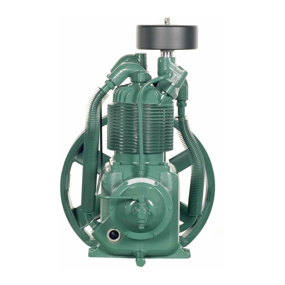
MODEL R15B COMPRESSOR
Form No. F3231
Ver: 02 01/08/2004
FEATURING THE R10 & R15 PUMPS
C453-A
(Ref. Drawing)
OPERATION/MAINTENANCE
MANUAL & PARTS LIST
MODEL HR2-6 UNIT
C452-A
(Ref. Drawing)
Advertisement
Table of Contents

Related Manuals for Champion R10D


Summary of Contents for Champion R10D
- Page 1 OPERATION/MAINTENANCE MANUAL & PARTS LIST TWO STAGE/TWO CYLINDER AIR COMPRESSORS & UNITS FEATURING THE R10 & R15 PUMPS THIS MANUAL CONTAINS IMPORTANT SAFETY INFORMATION AND SHOULD ALWAYS BE AVAILABLE TO THOSE PERSONNEL OPERATING THIS UNIT. READ, UNDERSTAND AND RETAIN ALL INSTRUCTIONS BEFORE OPERATING THIS EQUIPMENT TO PREVENT INJURY OR EQUIPMENT DAMAGE.
-
Page 2: Maintain Compressor Reliability And Performance With
They are ready to respond and assist you by providing fast, expert maintenance and repair services. For the location of your local authorized Champion Air Compressor distributor, refer to the yellow pages of your phone directory or contact: Factory:... -
Page 3: Table Of Contents
TABLE OF CONTENTS _______________________________________________________ Subject Page Safety And Operation Precautions..............4 Explanation Of Safety Instructions Symbols And Decals........5 Introduction ....................... 6 Warranty......................6 Dimensions And Specifications................. 7 Installation ..................8, 9, 10 & 11 Operation ....................11 & 12 Maintenance................. -
Page 4: Safety And Operation Precautions
Safety and Operation Precautions can result in injuries or equipment damage. However, Champion – A Gardner Denver Co., does not state as fact or does not mean to imply that the preceding list of Safety and Operating Precautions is all inclusive, and further that the observance of this list will prevent all injuries or equipment damage. -
Page 5: Explanation Of Safety Instructions Symbols And Decals
WARNING Indicates hazards or unsafe practice which could result in severe injury or death. CAUTION Indicates hazards or unsafe practice which could result in damage to the Champion compressor or minor injury. NOTICE Notice is used to notify people of installation, operation or maintenance information which is important but not hazard-related. -
Page 6: Introduction
Express Limited Warranty CHAMPION warrants each new air compressor unit manufactured by CHAMPION to be free from defects in material and workmanship under normal use and service for a period of twelve (12) months from date of installation or eighteen (18) months from date of shipment by CHAMPION or CHAMPION distributor, whichever may occur first. - Page 7 TWO STAGE AIR COMPRESSORS - MODELS R10D & R15B DIMENSIONS ITEM R10D & R15B Base-Width 10” Bolt Down-Width 4-3/8” Bolt Down to Edge 5/8” Base to Crank Ctr 5-1/2” Overall Width Overall Height 23-1/4” Bolt Down Hole Dia. 15/32” Base-Depth 7-1/2”...
-
Page 8: Installation
Tanks bolted directly to a concrete floor without padding will not be warranted against cracking. Champion vibro-isolators must be used for extended warranty to apply to ASME air receivers. If installing a bare pump or a base mounted unit, make certain the system has adequate pressure limiting controls. - Page 9 INSTALLATION (CONT’D) ELECTRICAL POWER SUPPLY It is essential that the power supply and the supply wiring are adequately sized and that the voltage correspond to the unit specifications. Branch circuit protection must be provided at installation a specified in the National Electrical Code. All wiring should be preformed by a licensed electrian or electrical contractor.
- Page 10 INSTALLATION (CONT’D) B1257-A (Ref. Drawing) B1258-A (Ref. Drawing)
-
Page 11: Operation
Air leaks waste energy and are expensive. Minimum Pipe Sizes For Compressor Air Lines (Based on clean Smooth Schedule 40 Pipe) MODEL 25’ 50’ 100’ 200’ 300’ R10D 3/4” 3/4” 3/4” 3/4” 3/4” R15B 3/4” (1”) 3/4” (1”) 3/4”... -
Page 12: Operation
OPERATION (CONT’D) Units furnished with head unloaders are equipped with a needle valve, pilot valve and head unloaders to provide continuous run capabilities. The pilot valve acts as an automatic air switch allowing air to flow from the receiver to the head unloader mechanism, thus actuating it. To operate unit in continuous run, open needle valve located next to pilot valve. -
Page 13: Maintenance
GUIDE TO MAINTENANCE To obtain reliable and satisfactory service, this unit requires a consistent preventive maintenance schedule. Maintenance schedule pages are included in the back of this manual to aid in keeping the proper records. WARNING Before performing any maintenance function, switch main disconnect switch to "off" position to assure no power is entering unit. - Page 14 EVERY 90 DAYS OR 500 HOURS MAINTENANCE Change crankcase oil. Use type and grade oil as specified in the section on "Compressor Oil Specifications". Check entire system for air leakage around fittings, connections, and gaskets, using soap solution and brush. Tighten nuts and capscrews as required.
- Page 15 GENERAL MAINTENANCE (Cont'd.) CENTRIFUGAL UNLOADER AND UNLOADER PRESSURE RELEASE VALVE: The centrifugal unloader is operated by two governor weights. It is totally enclosed and lubricated from the crankcase of the compressor. When compressor starts, the governor weights automatically open compressing the main spring, allowing the unloader pressure release valve to close. When the compressor stops, the main spring returns the governor weights to normal position opening the unloader pressure release valve and unloading the compressor.
- Page 16 COMPRESSOR PILOT VALVE PRESSURE ADJUSTMENT Proceed with the following instructions while compressor is running: Loosen locknut (4) and back off several turns. Do not turn differential pressure adjustment nut (3). Check reading on the tank pressure gauge. Set the compressor maximum pressure by turning threaded cap (1) clockwise to increase pressure or counter clockwise to decrease pressure.
-
Page 17: Compressor Oil Specifications
Do not mix oil types, weights or brands. NOTES: 1. Normal break-in period of Champion air compressors is 25 hours. 2. For the first 100 hours of compressor operation, a careful and regular check of the oil level should be made. Maintain oil level at the full line. -
Page 18: Troubleshooting Chart
TROUBLE SHOOTING CHART FOR COMPRESSOR Always disconnect unit from power supply and relieve all pressure from air tank before performing any maintenance. Failure to do so may result in equipment damage or injury. ALock Out" or "Tag Out" all power sources. WARNING Never operate unit without belt guard in place. - Page 19 Troubleshooting Chart (Cont’d Symptom Possible Cause(s) Corrective Action Air escapes from centrifugal unloader Centrifugal unloader release valve Clean or replace valve when unit is running dirty or detective. Air escapes from centrifugal unloader Check valve stuck in open position. Replace check valve. when unit is stopped.
- Page 20 PARTS ILLUSTRATION MODELS: HR1-3, HR1-6, HR1-8, HR2-3, HR2-6, HR2-8, HR3-3, HR3-6, HR3-8, HR3-12, HR5-3, HR5-6, HR5-8, HR5-12, HR7F-6, HR7F-8 & HR7F-12 C454-A (Ref. Drawing)
- Page 21 REPAIR PARTS LIST MODELS HR1-3 HR1-6 HR1-8 HR2-3 HR2-6 HR2-8 HR3-3 HR3-6 1. Pump R10D R10D R10D R10D R10D R10D R15B R15B 2. Pressure Gauge M519C M519C M519C M519C M519C M519C M519C M519C 3. Belt Guard Z307 Z307 Z307 Z307...
- Page 22 UNIT REPAIR PARTS ILLUSTRATION MODELS: VR1-6, VR1-8, VR2-6, VR2-8, VR3-6, VR3-8, VR3-12, VR5-6, VR5-8, VR5-12, VR7F-6, VR7F-8, & VR7F-12 13 (NOT SHOWN) 12 (NOT SHOWN) A.S.M.E. DATA PLATE C455-A (Ref. Drawing)
- Page 23 REPAIR PARTS LIST MODELS VR1-6 VR1-8 VR2-6 VR2-8 VR3-6 VR3-8 VR3-12 VR5-6 VR5-8 VR5-12 VR7F-6 VR7F-8 VR7F-12 1. Pump R10D R10D R10D R10D R15B R15B R15B R15B R15B R15B R15B R15B R15B 2. Pressure Gauge M519C M519C M519C M519C M519C...
- Page 24 UNIT REPAIR PARTS ILLUSTRATION MODELS: HR2D-8, HR2D-12, HR3D-8, HR3D-12 HR5D-8, HR5D-12, HR7DF-12 & HR7DF-25 C457-A (Ref. Drawing)
- Page 25 REPAIR PARTS LIST MODELS HR2D-8 HR2D-12 HR3D-8 HR3D-12 HR5D-8 HR5D-12 HR7DF-12 HR7DF-25 1. Pump R10D R10D R15B R15B R15B R15B R15B R15B 2. Pressure Gauge M519C M519C M519C M519C M519C M519C M519C M519C 3. Belt Guard Z307 Z307 Z307 Z307...
-
Page 26: Parts List
UNIT REPAIR PARTS ILLUSTRATION MODELS: BR-1, BR-2, BR-3, BR-5 & BR-7F 6 (NOT SHOWN) 5 (NOT SHOWN) REPAIR PARTS LIST MODELS BR-1 BR-2 BR-3 BR-5 BR-7F 1. Pump R10B R10B R15D R15D R15D 2. Belt Guard Z307 Z307 Z307 Z307 Z307 3. - Page 27 Compressor Repair Parts Illustration Models: R10D & R15B 36,37 36,37 C389-B (Ref. Drawing) Repair Parts List Compressor Models R10D & R15B Ref. No. Description Part No. Qty. Crankcase M1820 Pipe plug M2326 Flywheel NR7A Hex head cap screw M738 Hex nut...
- Page 28 Main Bearing ZRN16 Oil seal OSN4 Connecting rod assembly model R10D low pressure (includes items 37 thru 40) Z750 Connecting rod assembly model R10D high pressure (includes items 37 thru 40) Z752 Connecting rod assembly model R15B (includes items 37 thru 40)
- Page 29 Repair Parts List Compressor Models R10D & R15B Ref. No. Description Part No. Qty. Valve gasket P04134A Intake valve cage M2098 Valve spring RE1458 Valve disc RE1470 Intake valve seat RE1471 Unloader spring P04544A Low pressure intake manifold P09669C High pressure intake valve assembly...
- Page 30 Compressor Repair Parts Illustration Models: R10D & R15B C420-A (Ref. Drawing) ITEM PART NO. NAME REQ. M2868 Compression Fitting ZSB250A Tube, Unloading w/Fittings M2864 Compression Fitting ZUB375 Breather Tube w/Fittings M2864 Compression Fitting M2881 Compression Fitting Z9140 Intercooler w/Fittings...
-
Page 31: Constant Speed Head Unloader Kit
CONSTANT SPEED HEAD UNLOADER For Air Compressor Models R10D and R15B NOTE: This is optional equipment and may not be included on your unit. The purpose of constant speed unloading is to provide a means of stopping or starting the compression of air by the compressor without stopping or starting the electric motor or gasoline engine after each cycle. - Page 32 UNIT HAZARD DECAL LISTING PAGE DESCRIPTION PART NO. PRODUCT LIABILITY DECAL SHEET - MASTER P10157A Unit Pressure Setting NOT USED DANGER – Breathing Air DANGER – Drain Tank Daily WARNING – Pressure/Safety Valve NOT USED DANGER – Valve Maintenance DANGER – High Voltage WARNING –...
- Page 33 UNIT HAZARD DECALS...
-
Page 34: Pump Hazard Decals & Tags
PUMP HAZARD DECALS... -
Page 35: Record Of Maintenance Service
RECORD OF MAINTENANCE SERVICE DAILY • CHECK OIiL LEVEL • DRAIN MOISTURE FROM TANK WEEKLY MONTHLY EVERY 3 MONTHS • • INSPECT AIR SYSTEM • CLEAN FILTER CHANGE OIL • • CLEAN COMPRESSOR INSPECT VALVE ASSEMBLIES • • CHECK V-BELTS TIGHTEN ALL FASTENERS •... - Page 36 Phone (815) 875-3321 Fax (815) 872-0421 E-mail: champion@championpneumatic.com Copyright 8 2004 Gardner Denver, Inc. Plants in Princeton, IL, and Manteca, CA Printed in U.S.A. Due to Champion=s continuing product development program, specifications and materials are subject to change without notice or obligation...
Need help?
Do you have a question about the R10D and is the answer not in the manual?
Questions and answers