Table of Contents
Advertisement
Quick Links
Download this manual
See also:
Operating Instructions
SERVICE MANUAL
Ver 1.0 2004. 04
SPECIFICATIONS
Frequency range:
Band
ICF-704S
FM
87.5 - 108.0 MHz
SW
5.95 - 18 MHz
MW
530 - 1605 kHz
Speaker:
Approx. 10.2 cm (4
inches) dia. 8 ohms
1/8
Power output:
450 mW (at 10 % harmonic distortion)
Output:
v (earphone) (ø 3.5 mm minijack)
Power requirements:
230 V AC, 50 Hz
6V DC, four R6 (size AA) batteries
Dimensions:
Approx. 282.5 × 153.5 × 83.5 mm (w/h/d)
× 6
× 3
(11
inches) incl. projecting parts
1/8
1/8
3/8
and control with carrying handle pushed in.
Mass:
Approx. 1211 g (2 lb 10.7 oz) incl. batteries
Supplied accessory:
AC power cord (1)
Design and specifications are subject to change without
notice.
Sony Corporation
9-877-784-01
2004D04-1
Personal Audio Company
© 2004. 04
Published by Sony Engineering Corporation
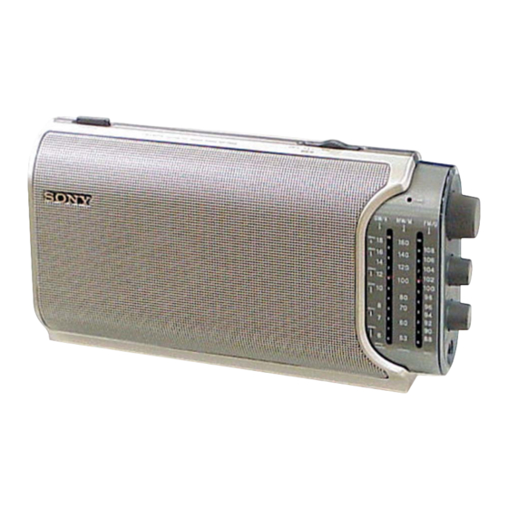
ICF-704S
Australian Model
FM/SW/MW 3 BAND RADIO
1
Advertisement
Table of Contents

Related Manuals for Sony ICF-704S


Summary of Contents for Sony ICF-704S
- Page 1 Approx. 1211 g (2 lb 10.7 oz) incl. batteries Supplied accessory: AC power cord (1) Design and specifications are subject to change without notice. FM/SW/MW 3 BAND RADIO Sony Corporation 9-877-784-01 2004D04-1 Personal Audio Company © 2004. 04 Published by Sony Engineering Corporation...
-
Page 2: Table Of Contents
COMPONENTS IDENTIFIED BY MARK 0 OR DOTTED LINE WITH MARK 0 ON THE SCHEMATIC DIAGRAMS AND IN THE PARTS LIST ARE CRITICAL TO SAFE OPERATION. REPLACE THESE COMPONENTS WITH SONY PARTS WHOSE PART NUMBERS APPEAR AS SHOWN IN THIS MANUAL OR IN SUPPLEMENTS PUBLISHED BY SONY. -
Page 3: General
Battery life (Approx. hours) (JEITA*) Banda When using SW AM(MW) LW Sony alkaline LR6 (size AA) TUNE indicator Sony R6 (size AA) Indicateur TUNE TUNE-Anzeige * Measured by JEITA (Japan Electronics and Indicador de sintonia (TUNE) HIGH Information Technology Industries Association) Indicatore TUNE Standards. -
Page 4: Disassembly
ICF-704S SECTION 2 DISASSEMBLY Note : This set can be disassemble according to the following sequence. 2-1. CABINET (FRONT) ASSY (Page 5) 2-2. CHASSIS SECTION (Page 5) 2-3. MAIN BOARD (Page 6) 2-4. SETTING THE POINTER (Page 6) -
Page 5: Cabinet (Front) Assy
ICF-704S Note : Follow the disassembly procedure in the numerical order given. 2-1. CABINET (FRONT) ASSY 5 two BV tapping screws (B2.6) 8 screw handle (M3) 7 two BV tapping screws (B2.6) 0 antenna contact plate 6 two BV tapping screws (B2.6) -
Page 6: Main Board
ICF-704S 2-3. MAIN BOARD 0 MAIN board 4 BV tapping screw 9 chassis assy (B2.6) 5 claw 3 VC drum 1 two knobs (control) 2 screw 6 claw (M2.6) 2-4. SETTING THE POINTER • Setting the Pointer 1. Rotate the VC drum in the direction of the arrow until it is stopped. -
Page 7: Electrical Adjustments
ICF-704S SECTION 3 ELECTRICAL ADJUSTMENTS MW SECTION SW SECTION BAND switch : MW BAND switch : SW AM RF signal AM RF signal telescopic Put the lead-wire generator generator antenna terminal antenna close to the set. 10pF 400Hz, 30% 400Hz, 30%... -
Page 8: Fm Section
ICF-704S FM SECTION • Repeat the procedures in each adjustment several times, and the frequency coverage and tracking adjustments should be finally done by the trimmer capacitors. BAND switch : FM FM FREQUENCY COVERAGE ADJUSTMENT FM RF signal telescopic generator... -
Page 9: Diagrams
ICF-704S SECTION 4 DIAGRAMS 4-1. NOTE FOR PRINTED WIRING BOARDS AND SCHEMATIC DIAGRAMS THIS NOTE IS COMMON FOR PRINTED WIRING BOARDS AND SCHEMATIC DIAGRAMS. (In addition to this, the necessary note is printed in each block.) For schematic diagrams. For printed wiring boards. -
Page 10: Printed Wiring Board - Main Section
ICF-704S 4-2. PRINTED WIRING BOARD — MAIN SECTION — MAIN BOARD ANT1 FM/SW TELESCOPIC ANTENNA BPF1 POWER BOARD W101 (Page 11) S1-5 S1-6 AM FERRITE ROD BAR ANTENNA CV1-3 CV1-1 CT1-3 CT1-1 (FM RF) (AM RF) S1-3 S1-4 CV1-2 CT1-2... -
Page 11: Printed Wiring Boards - Power Section
ICF-704S 4-3. PRINTED WIRING BOARDS — POWER SECTION — POWER BOARD SWITCH BOARD W103 S101 S101 OPERATE T101 STANDBY W103 1-861-816- DRY BATTERY SIZE "AA" (IEC DESIGNATION LR6) 4PCS,6V AC INLET BOARD W101 W102 J101 ~ AC IN W102 C101... -
Page 12: Schematic Diagram
ICF-704S 4-4. SCHEMATIC DIAGRAM S1-3 S1-1 CV1-1 CV1-2 S1-4 ANT1 S1-2 JW13 S1-5 JW14 BPF1 JW15 S101 W103 W103 R101 JW16 W102 W102 C103 JW12 JW11 C101 JW10 T101 D101 J101 S1-6 D102 C102 W101... -
Page 13: Exploded Views
ICF-704S SECTION 5 EXPLODED VIEWS NOTE: • The mechanical parts with no reference • Color Indication of Appearance Parts The components identified by mark 0 or dotted line with mark number in the exploded views are not supplied. Example : 0 are critical for safety. -
Page 14: Cabinet (Rear) Section
ICF-704S 5-2. CABINET (REAR) SECTION ANT1 not supplied J101 T101 not supplied The components identified by mark 0 or dotted line with mark. 0 are critical for safety. Replace only with part number specified. Ref. No. Part No. Description Remark Ref. -
Page 15: Electrical Parts List
ICF-704S SECTION 6 AC INLET MAIN ELECTRICAL PARTS LIST NOTE: • Due to standardization, replacements in • Items marked “*” are not stocked since The components identified by mark 0 or dotted line with mark. the parts list may be different from the they are seldom required for routine service. - Page 16 ICF-704S MAIN POWER SWITCH Ref. No. Part No. Description Remark Ref. No. Part No. Description Remark < COIL > 1-861-816-11 SWITCH BOARD ************* 1-428-291-11 COIL, AIR-CORE 1-428-291-11 COIL, AIR-CORE < RESISTOR > 1-428-222-11 COIL, FM OSC 1-754-132-21 ANTENNA, FERRITE-ROD (MW)
- Page 17 ICF-704S MEMO...
- Page 18 ICF-704S REVISION HISTORY Clicking the version allows you to jump to the revised page. Also, clicking the version at the upper on the revised page allows you to jump to the next revised page. Ver. Date Description of Revision 2004. 04...
Need help?
Do you have a question about the ICF-704S and is the answer not in the manual?
Questions and answers