
Related Manuals for Victor Cutmaster 52


Summary of Contents for Victor Cutmaster 52
- Page 1 208- 460V 600V 230V CUTMASTER ™ PLASMA CUTTING SYSTEM Operating Manual Art # A-08617_AD Revision: AQ Issue Date: October 3, 2013 Manual No.: 0-4961 VictorThermalDynamics.com...
- Page 2 WE APPRECIATE YOUR BUSINESS! Congratulations on your new Victor Thermal Dynamics product. We are proud to have you as our customer and will strive to provide you with the best service and reliability in the industry. This product is backed by our extensive warranty and world-wide service network. To locate your nearest distributor or service agency call 1-800-426-1888, or visit us on the web at www.VictorThermalDynamics.com.
- Page 3 Manufacturer assumes no liability for its use. Plasma Cutting Power Supply CutMaster™ 52 SL60 1Torch™ Operating Manual Number 0-4961 Published by: Victor Technologies International, Inc. 82 Benning Street West Lebanon, New Hampshire, USA 03784 (603) 298-5711 www.victorthermaldynamics.com Copyright 2007, 2008, 2009, 2010, 2011, 2012, 2013 by Victor Technologies International, Inc.
- Page 4 This Page Intentionally Blank...
-
Page 5: Table Of Contents
TABLE OF CONTENTS SECTION 1: GENERAL INFORMATION ..............1-1 1.01 Notes, Cautions and Warnings ................ 1-1 1.02 Important Safety Precautions ................. 1-1 1.03 Publications ....................1-2 1.04 Note, Attention et Avertissement ..............1-3 1.05 Precautions De Securite Importantes ............. 1-3 1.06 Documents De Reference ................ - Page 6 TABLE OF CONTENTS SECTION 4 TORCH: OPERATION ................ 4T-1 4T.01 Torch Parts Selection ..................4T-1 4T.02 Cut Quality .....................4T-1 4T.03 General Cutting Information ................4T-2 4T.04 Hand Torch Operation ..................4T-2 4T.05 Gouging ......................4T-5 4T.06 Mechanized Torch Operation ................4T-6 4T.07 Parts Selection for Manual and Mechanized Torch Cutting ......4T-7 4T.08 Recommended Cutting Speeds for Mechanized Torch With Exposed Tip ..4T-8 4T.09...
-
Page 7: Section 1: General Information
CUTMASTER 52 SECTION 1: To prevent possible injury, read, understand and follow all warnings, safety precautions GENERAL INFORMATION and instructions before using the equipment. Call 1-603-298-5711 or your local distributor if you have any questions. 1.01 Notes, Cautions and Warnings Throughout this manual, notes, cautions, and warnings are used to highlight important information. -
Page 8: Publications
CUTMASTER 52 • Wear dry gloves and clothing. Insulate yourself from the work piece or other parts of the welding circuit. PLASMA ARC RAYS • Repair or replace all worn or damaged parts. Plasma Arc Rays can injure your eyes and burn your skin. -
Page 9: Note, Attention Et Avertissement
CUTMASTER 52 NOTE PROTECTION, obtainable from American National Standards Institute, 1430 Broadway, New York, NY Toute opération, procédure ou renseigne- 10018 ment général sur lequel il importe d’insister 5. ANSI Standard Z41.1, STANDARD FOR MEN’S davantage ou qui contribue à l’efficacité de SAFETY-TOE FOOTWEAR, obtainable from the fonctionnement du système. - Page 10 CUTMASTER 52 Il faut communiquer aux opérateurs et au • Le phosgène, un gaz toxique, est généré par la fumée personnel TOUS les dangers possibles. Afin provenant des solvants et des produits de nettoyage d’éviter les blessures possibles, lisez, compre- chlorés.
- Page 11 CUTMASTER 52 • Prévoyez une veille d’incendie lors de tout travail dans une zone présentant des dangers d’incendie. BRUIT • Le gas hydrogène peut se former ou s’accumuler sous les pièces de travail en aluminium lorsqu’elles sont Le bruit peut provoquer une perte permanente de l’ouïe.
-
Page 12: Documents De Reference
CUTMASTER 52 1.06 Documents De Reference Consultez les normes suivantes ou les révisions les plus récentes ayant été faites à celles-ci pour de plus amples renseignements : 1. OSHA, NORMES DE SÉCURITÉ DU TRAVAIL ET DE PROTECTION DE LA SANTÉ, 29CFR 1910, disponible auprès du Superintendent of Documents, U.S. -
Page 13: Declaration Of Conformity
* CSA E60974-1: 2012 Arc Welding Equipment - Part 1: Welding Power Sources * IEC 60974-1: 2012 Arc Welding Equipment - Part 1: Welding Power Sources Victor Technologies has been manufacturing products for more than 30 years, and will continue to achieve excellence in our area of manufacture. -
Page 14: Statement Of Warranty
Victor Technologies, Inc. will honor warranty claims submitted within the warranty periods listed below. All warranty periods begin on the date of sale of the product to the original retail customer or 1 year after sale to an authorized Victor Thermal Dynamics Distributor. -
Page 15: Section 2 System: Introduction
Warnings will be enclosed in a box such as this. Additional copies of this manual may be purchased by contacting Victor Technologies International at the address and phone number in your area listed on back cover of this manual. Include the Owner’s Manual number and equipment identification numbers. -
Page 16: Power Supply Specifications
20 - 60 Amps, Continuously Adjustable Power Supply Gas Particulates to 5 Microns Filtering Ability CutMaster 52 Power Supply Duty Cycle * Duty Cycle Ratings @ 40° C (104° F) Ambient Temperature Operating Range 0° - 50° C IEC Rating... -
Page 17: Input Wiring Specifications
CUTMASTER 52 2.05 Input Wiring Specifications CutMaster 52 Power Supply Input Cable Wiring Requirements Input voltage Freq Power Input Suggested Sizes Flexible Cord Volts I max Fuse (amps) (Min. AWG) 10.4 1 Phase 10.8 15.2 50/60 50/60 3 Phase 50/60... -
Page 18: Power Supply Features
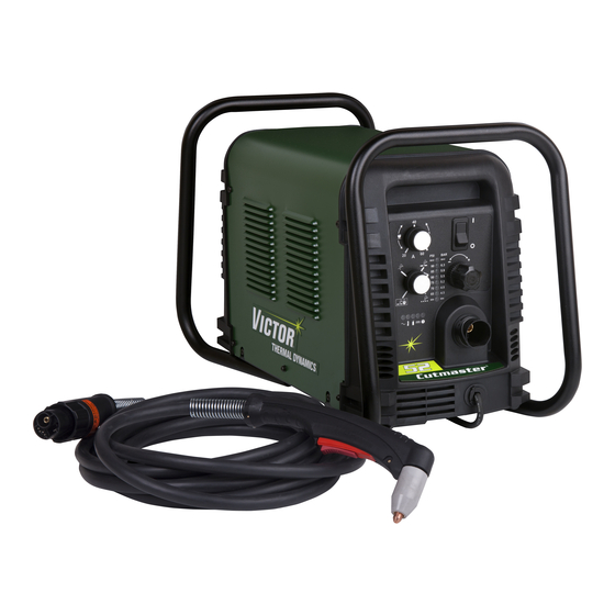
CUTMASTER 52 2.06 Power Supply Features Handle and Leads Wrap Control Panel Torch Leads Receptacle Art # A-07942 Work Cable and Clamp Port for Optional Automation Interface Cable Input Power Selection Filter Assembly Gas Inlet Port Art # A-07981 Input Power Cord... -
Page 19: Section 2 Torch: Introduction
CUTMASTER 52 SECTION 2 TORCH: 10.125" (257 mm) INTRODUCTION 2T.01 Scope of Manual 3.75" (95 mm) This manual contains descriptions, operating instruc- Art # A-03322_AB tions and maintenance procedures for the 1Torch Models 1.17" (29 mm) SL60/Manual and SL100/Mechanized Plasma Cut- ting Torches. -
Page 20: 04 Options And Accessories
CUTMASTER 52 Torch Ratings 2T.05 Introduction to Plasma Manual Torch Ratings A. Plasma Gas Flow Ambient 104° F Plasma is a gas which has been heated to an ex- Temperature 40° C tremely high temperature and ionized so that it... - Page 21 CUTMASTER 52 The plasma gas flows into the torch through the Remote Pendant negative lead, through the starter cartridge, around the electrode, and out through the tip orifice. The secondary gas flows down around the outside of the torch starter cartridge, and out between the...
- Page 22 CUTMASTER 52 This Page Intentionally Blank INTRODUCTION Manual 0-4961 2T-4...
-
Page 23: Section 3 System: Installation
CUTMASTER 52 SECTION 3 SYSTEM: INSTALLATION 3.01 Unpacking 1. Use the packing lists to identify and account for each item. 2. Inspect each item for possible shipping damage. If damage is evident, contact your distributor and / or shipping company before proceeding with the installation. - Page 24 CUTMASTER 52 NOTE 7. With a little slack in the wires, tighten the through - hole protector to secure the power cable. There is only one jumper setting that changes between the single and three phase settings. 8. Reinstall the Power Supply cover per instructions To change from single phase to three phase, found in Section 5.
-
Page 25: Gas Connections
CUTMASTER 52 NOTE 7. With a little slack in the wires, tighten the through - hole protector to secure the power cable. For a secure seal, apply thread sealant to the fitting threads, according to the maker's in- 8. Reinstall the Power Supply cover per instructions structions. - Page 26 CUTMASTER 52 Regulator/Filter Assembly 2-Stage Filter Inlet Port (IN) Regulator Input Outlet Port (OUT) Two Stage Filter Hose Clamp Assembly Gas Supply Hose 1/4 NPT to 1/4” (6mm) Fitting Art # A-07945_AC Optional Two - Stage Filter Installation Using High Pressure Air Cylinders When using high pressure air cylinders as the air supply: 1.
-
Page 27: Section 3 Torch: Installation
CUTMASTER 52 SECTION 3 TORCH: 3. Place a welding filter lens in front of the torch and turn ON the air. Do not start an arc! INSTALLATION Any oil or moisture in the air will be visible on the lens. - Page 28 CUTMASTER 52 This Page Intentionally Blank INSTALLATION Manual 0-4961 3T-2...
-
Page 29: Section 4 System: Operation
CUTMASTER 52 SECTION 4 SYSTEM: OPERATION 4.01 Front Panel Controls / Features See Illustration for numbering Identification 1. Output Current Control Sets the desired output current. Output settings up to 60 Amps may be used for drag cutting (with the torch tip contacting the workpiece) or for standoff cutting. -
Page 30: Preparations For Operation
CUTMASTER 52 4.02 Preparations for Operation Power ON Place the Power Supply ON / OFF switch to the ON At the start of each operating session: (up) position. AC indicator turns ON. Gas indicator turns ON if there is sufficient gas pres-... - Page 31 CUTMASTER 52 Typical Cutting Speeds STANDOFF CutMaster 52 Gas Pressure Settings Cutting speeds vary according to torch output am- perage, the type of material being cut, and operator Leads SL60 SL100 skill. Refer to Section "4T.08 Recommended Cutting Length (Hand Torch) (Mechanized Torch) Speeds for Mechanized Torch With Exposed Tip"...
- Page 32 CUTMASTER 52 This Page Intentionally Blank OPERATION Manual 0-4961...
-
Page 33: Section 4 Torch: Operation
CUTMASTER 52 SECTION 4 TORCH: OPERATION Torch Head Electrode 4T.01 Torch Parts Selection Depending on the type of operation to be done deter- mines the torch parts to be used. Start Cartridge Type of operation: Drag cutting, standoff cutting or gouging... -
Page 34: 03 General Cutting Information
CUTMASTER 52 Kerf Width 4T.03 General Cutting Information Cut Surface Bevel Angle WARNING Spatter Disconnect primary power at the source be- fore disassembling the power supply, torch, Top Edge or torch leads. Rounding Frequently review the Important Safety Pre- cautions at the front of this manual. Be sure... -
Page 35: 04 Hand Torch Operation
CUTMASTER 52 NOTE Left Side Cut Angle The tip should never come in contact with Right Side Cut Angle the workpiece except during drag cutting operations. 2. Depending on the cutting operation, do one of the following: a. For edge starts, hold the torch perpendicular... - Page 36 CUTMASTER 52 NOTE Shield Cup With Straight Edge The gas preflow and postflow are a character- The drag shield cup can be used with a non conductive istic of the power supply and not a function straight edge to make straight cuts by hand.
- Page 37 CUTMASTER 52 Piercing With Hand Torch 1. The torch can be comfortably held in one hand or steadied with two hands. Position the hand to press the Trigger on the torch handle. With the hand torch, the hand may be positioned close to...
-
Page 38: 05 Gouging
CUTMASTER 52 7. Clean spatter and scale from the shield cup and the tip as soon as possible. Spraying the shield cup in anti - spatter compound will minimize the CAUTION amount of scale which adheres to it. Touching the torch tip or shield cup to the work surface will cause excessive parts wear. -
Page 39: 06 Mechanized Torch Operation
CUTMASTER 52 Slag Buildup Slag generated by gouging on materials such as carbon and stainless steels, nickels, and alloyed steels, can be removed easily in most cases. Slag does not obstruct the gouging process if it accumulates to the side of the gouge path. - Page 40 CUTMASTER 52 For optimum smooth surface quality, the travel speed should be adjusted so that only the leading edge of the arc column produces the cut. If the travel speed is too slow, a rough cut will be produced as the arc moves from side to side in search of metal for transfer.
-
Page 41: 07 Parts Selection For Manual And Mechanized Torch Cutting
9-8241 9-8237 Tips: Tip Gouging A 9-8225 (40 Amps Max.) NOTE CutMaster 52 uses 60A and less Tip Gouging B 9-8226 (50 - 100 Amps) CutMaster 82 uses 80A and less CutMaster 102 uses 100A and less Art # A-08065_AE... -
Page 42: 08 Recommended Cutting Speeds For Mechanized Torch With Exposed Tip
CUTMASTER 52 4T.08 Recommended Cutting Speeds for Mechanized Torch With Exposed Tip Type Torch: SL60 With Exposed Tip Type Material: Mild Steel Type Plasma Gas: Air Type Secondary Gas: Single Gas Torch Speed (Per Plasma Gas Pierce Thickness Output Amperage... - Page 43 CUTMASTER 52 Type Torch: SL60 With Exposed Tip Type Material: Mild Steel Type Plasma Gas: Air Type Secondary Gas: Single Gas Torch Speed (Per Plasma Gas Pierce Thickness Output Amperage Standoff Flow (CFH) Pierce Minute) Press Height (Cat. Volts Delay...
- Page 44 CUTMASTER 52 Type Torch: SL60 With Exposed Tip Type Material: Aluminum Type Plasma Gas: Air Type Secondary Gas: Single Gas Torch Speed (Per Plasma Gas Pierce Thickness Output Amperage Standoff Flow (CFH) Pierce Minute) Press Height (Cat. Volts Delay Inches...
-
Page 45: 09 Recommended Cutting Speeds For Mechanized Torch With Shielded Tip
CUTMASTER 52 4T.09 Recommended Cutting Speeds for Mechanized Torch With Shielded Tip Type Torch: SL60 With Shielded Tip Type Material: Mild Steel Type Plasma Gas: Air Type Secondary Gas: Single Gas Torch Speed (Per Plasma Gas Pierce Thickness Output Amperage... - Page 46 CUTMASTER 52 Type Torch: SL60 With Shielded Tip Type Material: Mild Steel Type Plasma Gas: Air Type Secondary Gas: Single Gas Torch Speed (Per Plasma Gas Pierce Thickness Output Amperage Standoff Flow (CFH) Pierce Minute) Press Height Volts Delay Inches (Cat.
- Page 47 CUTMASTER 52 Type Torch: SL60 With Shielded Tip Type Material: Aluminum Type Plasma Gas: Air Type Secondary Gas: Single Gas Torch Speed (Per Plasma Gas Pierce Thickness Output Amperage Standoff Flow (CFH) Pierce Minute) Press Height (Cat. Volts Delay Inches...
-
Page 48: Patent Information
CUTMASTER 52 PATENT INFORMATION Plasma Cutting Torch Patents The following parts are covered under U.S. and Foreign Patents as follows: Catalog # Description Patent(s) 9-8215 Electrode US Pat No(s) 6163008; 6987238 Other Pat(s) Pending 9-8213 Cartridge US Pat No(s) 6903301; 6717096; 6936786;... - Page 49 CUTMASTER 52 Catalog # Description Patent(s) 9-8245 Shield Cap US Pat No(s) 6914211; D496951 Other Pat(s) Pending The following parts are also licensed under U.S. Patent No. 5,120,930 and 5,132,512: Catalog # Description 9-8235 Shield Cap 9-8236 Shield Cap 9-8237...
- Page 50 CUTMASTER 52 This Page Intentionally Blank OPERATION Manual 0-4961 4T-18...
-
Page 51: Section 5 System: Service
CUTMASTER 52 SECTION 5 SYSTEM: SERVICE 5.01 General Maintenance Maintain more often Warning! if used under severe Disconnect input power before maintaining. conditions Each Use Visual check of torch tip and electrode Weekly Visually inspect the cables and leads. Replace as needed... -
Page 52: Maintenance Schedule
CUTMASTER 52 5.02 Maintenance Schedule 5.03 Common Faults Problem - Symptom Common Cause NOTE Insufficient 1. Cutting speed too fast. The actual frequency of maintenance may Penetration 2. Torch tilted too much. need to be adjusted according to the operat- 3. -
Page 53: Fault Indicator
CUTMASTER 52 5.04 Fault Indicator At initial power up, two lights will temporarily illuminate for 2-3 seconds to show the version of software used. To determine the first digit, count the function indicators left to right, 1 through 5. To determine the second digit count the pressure indicators, reading from bottom to top, 0 through 7. -
Page 54: Basic Troubleshooting Guide
CUTMASTER 52 5.05 Basic Troubleshooting Guide WARNING There are extremely dangerous voltage and power levels present inside this unit. Do not attempt to diagnose or repair unless you have had training in power electronics measurement and troubleshooting techniques. Problem - Symptom Possible Cause... - Page 55 CUTMASTER 52 Problem - Symptom Possible Cause Recommended Action FAULT & 80 PSI 1. Torch shield cup is loose. 1. Tighten shield cup by hand. Do not overtighten. indicators flashing. 2. Torch tip, electrode or starter 2. Turn OFF power supply. Remove shield cup. Install Gas flow is cycling cartridge missing.
-
Page 56: Power Supply Basic Parts Replacement
CUTMASTER 52 5.06 Power Supply Basic Parts Replacement C. Filter Element Assembly Replacement The Filter Element Assembly is in the rear panel. For better system performance, the filter element should be checked per the Maintenance Schedule (Section 5.02), WARNING and either cleaned or replaced. - Page 57 CUTMASTER 52 6. Disconnect the input line from the filter element assembly. Housing 7. Remove the filter element assembly through the rear opening. NOTE Filter Element If replacing or cleaning just the filter element (Cat. No. 9-7741) refer to the following illustration for disas- sembly.
- Page 58 CUTMASTER 52 First & Second Stage Cartridges (as marked) Art # A-02942 Optional Two-Stage Filter Replacement 6. Slide the replacement Filter Elements into the Filter Assembly, with the same orientation as noted in Step 4 above. 7. Hand tighten the two bolts evenly, then torque each bolt to 20 - 30 in-lbs (2.3 - 3.4 Nm). Improper torque may damage the gasket.
-
Page 59: Section 5 Torch: Service
CUTMASTER 52 SECTION 5 TORCH: SERVICE Upper Groove 5T.01 General Maintenance with Vent Holes Must Remain Open NOTE Upper O-Ring Refer to Previous "Section 5: System" for com- in Correct Groove mon and fault indicator descriptions. Threads Cleaning Torch Lower O-Ring... -
Page 60: 02 Inspection And Replacement Of Consumable Torch Parts
CUTMASTER 52 5T.02 Inspection and Replacement of 4. Remove the tip. Check for excessive wear (indi- cated by an elongated or oversized orifice). Clean Consumable Torch Parts or replace the tip if necessary. Worn Tip Good Tip WARNING Disconnect primary power to the system before disassembling the torch or torch leads. -
Page 61: Section 6: Parts Lists
The following items are included with the replacement power supply: work cable & clamp, input power cable, gas pressure regulator / filter, and operating manual. Description Catalog # CutMaster 52 Power Supply 208/230 - 460VAC, Single or 3 Phase, 60Hz, with input power cable and plug 3-5130-1... -
Page 62: Options And Accessories
CUTMASTER 52 NOTE *9-0115 regulator, If the serial number of the power supply is prior to #05078755 then kit number 9-0201 will be needed to replace not only the regulator (9-0115) but the logic PCB as well. Another way to tell if the kit is needed is to see if the regulator has a small diameter tube coming out of the bottom fitting. -
Page 63: Replacement Parts For Hand Torch
CUTMASTER 52 6.06 Replacement Parts for Hand Torch Item # Description Catalog # Torch Handle Replacement Kit (includes items No. 2 & 3) 9-7030 Trigger Assembly Replacement Kit 9-7034 Handle Screw Kit (5 each, 6-32 x 1/2” cap screw, and wrench) 9-8062 Torch Head Assembly Replacement Kit (includes items No. -
Page 64: Replacement Parts - For Machine Torches With Unshielded Leads
CUTMASTER 52 6.07 Replacement Parts - for Machine Torches with Unshielded Leads Item No. Description Catalog No. Torch Head Assembly without leads (includes items 2, 3, and 14) 9-8220 Large O-Ring 8-3487 Small O-Ring 8-3486 PIP Switch Kit 9-7036 Unshielded Automated Leads Assemblies with ATC connectors 5 - foot / 1.5 m Leads Assembly with ATC connector... - Page 65 CUTMASTER 52 5 & 6 A-07994_AB Manual 0-4961 PARTS LIST...
-
Page 66: Replacement Shielded Machine Torch Leads Assemblies
CUTMASTER 52 6.08 Replacement Shielded Machine Torch Leads Assemblies Item No. Description Catalog No. Mechanized Shielded Leads Assemblies with ATC Connectors 5 - foot / 1.5 m Leads Assembly with ATC Connector 4-7846 10 - foot / 3.05 m Leads Assembly with ATC Connector 4-7847 25 - foot / 7.6 m Leads Assembly with ATC Connector... -
Page 67: Torch Consumable Parts (Sl60)
9-8241 9-8237 Tips: Tip Gouging A 9-8225 (40 Amps Max.) NOTE CutMaster 52 uses 60A and less Tip Gouging B 9-8226 (50 - 100 Amps) CutMaster 82 uses 80A and less CutMaster 102 uses 100A and less Art # A-08065_AE... -
Page 68: Torch Consumable Parts (Sl100)
CUTMASTER 52 6.10 Torch Consumable Parts (SL100) Ohmic Clip Automation Torch Ohmic Clip 9-8224 Manual Torch 9-8259 20-40A Shield Tip: Shield Cap, Machine Cup Body, STANDOFF 40A 9-8245 9-8237 CUTTING 9-8205 Shield Cap, Deflector Shield Cup 9-8206 9-8243 9-8218 9-8208... -
Page 69: Appendix 1: Sequence Of Operation (Block Diagram
CUTMASTER 52 APPENDIX 1: SEQUENCE OF OPERATION (BLOCK DIAGRAM) ACTION: ACTION: ACTION: ACTION: RUN / Rapid Auto Restart / ON / OFF switch to ON Close external RUN / SET / LATCH disconnect switch. Rapid Auto Restart / switch to RUN... -
Page 70: Appendix 2: Data Tag Information
CUTMASTER 52 APPENDIX 2: DATA TAG INFORMATION West Lebanon, NH USA 03784 Manufacturer's Name and/or Logo, Location, Model and Revision Level, Serial Number M odel : and Production Code Dat e of M f r : Made in USA Type of Power... -
Page 71: Appendix 3: Torch Pin - Out Diagrams
CUTMASTER 52 APPENDIX 3: TORCH PIN - OUT DIAGRAMS A. Hand Torch Pin - Out Diagram ATC Female Receptacle ATC Male Connector Front View Front View Negative / Negative / Plasma Plasma 8 - Open 8 - Ground 4 - Green /... -
Page 72: Appendix 4: Torch Connection Diagrams
CUTMASTER 52 APPENDIX 4: TORCH CONNECTION DIAGRAMS A. Hand Torch Connection Diagram Torch: SL60 / SL100 Hand Torch Leads: Torch Leads with ATC Connector Power Supply: with ATC Receptacle Male ATC Leads ATC Female Power Connector Receptacle Torch Torch Supply... - Page 73 CUTMASTER 52 This Page Intentionally Blank Manual 0-4961 APPENDIX...
-
Page 74: Appendix 5: System Schematic, 208/460V Units
CUTMASTER 52 APPENDIX 5: SYSTEM SCHEMATIC, 208/460V UNITS K1-K4 K1-K4 K5, K6 K5, K6 PRI 2 PRI 2 PRI 1 PRI 1 PRI 4 PRI 4 PRI 3 PRI 3 +12VDC BIAS SUPPLY MTH2 MTH2 MTH1 MTH1 C1-C4* C1-C4* /INRUSH... - Page 75 DWG No: TITLE: TITLE: TITLE: Last Modified: Last Modified: Last Modified: Monday, March 30, 2009 Monday, March 30, 2009 Monday, March 30, 2009 13:16:29 13:16:29 13:16:29 CUTMASTER 52/82/A40/A60 230/460V CUTMASTER 52/82/A40/A60 230/460V CUTMASTER 52/82/A40/A60 230/460V 42X1298 42X1298 42X1298 Manual 0-4961 APPENDIX...
-
Page 76: Appendix 6: System Schematic, 600V Units
CUTMASTER 52 APPENDIX 6: SYSTEM SCHEMATIC, 600V UNITS PRI 1 PRI 1 PRI 2 PRI 2 PRI 4 PRI 4 PRI 3 PRI 3 BIAS SUPPLY MTH2 MTH2 MTH1 MTH1 +12VDC + C1-C4* + C1-C4* CHOKE /INRUSH CE UNITS ONLY... - Page 77 CUTMASTER 52 1TORCH PIP SWITCH PIP SWITCH SEC1 SEC1 SEC2 SEC2 CHOKE1 CHOKE1 +12VDC TORCH SWITCH TORCH SWITCH TEMP /OVERTEMP CIRCUIT ATC CONNECTOR AUTOMATION TORCH SOLENOID -V OUT 1 -V OUT 1 ELECTRODE1 ELECTRODE1 TIP1 TIP1 PILOT IGBT PILOT IGBT...
-
Page 78: Appendix 7: Publication History
Added Opening the Contactor Cover text per ECOB2122. Inserted Victor Technologies branding text. Nov. 26, 2012 Changed logo on Front Cover and Inside Front Cover from "Thermal Dynamics" to "Victor Thermal Dynamics", modified Prop 65 text Section 1, changed wording for "NOTE" below Subsection 3T.02 pg. - Page 79 This Page Intentionally Blank...
- Page 80 I N N O V A T I O N T O S H A P E T H E W O R L D ™ U.S. Customer Care: 800-426-1888 / FAX 800-535-0557 Canada Customer Care: 905-827-4515 / FAX 800-588-1714 International Customer Care: 940-381-1212 / FAX 940-483-8178 Printed in Mexico © 2012 Victor Technologies International, Inc. www.victortechnologies.com...
Need help?
Do you have a question about the Cutmaster 52 and is the answer not in the manual?
Questions and answers