
Related Manuals for Victor 42 CUTMASTER


Summary of Contents for Victor 42 CUTMASTER
-
Page 1: Service Manual
CUTMASTER ® plASMA CUTTing SySTEM 120V 15A 120V 20A 230V 20A Art # A-10241_AC Service Manual Revision: AF Issue Date: January 31, 2013 Manual No.: 0-5171 Operating Features: PHASE... - Page 2 YOU ARE IN GOOD COMPANY! The Brand of Choice for Contractors and Fabricators Worldwide. Thermal Dynamics is a Global Brand of manual and automation Plasma Cutting Products for Victor Technologies Inc. We distinguish ourselves from our competition through market-leading, dependable products that have stood the test of time.
- Page 3 Plasma Cutting Power Supply Cutmaster ® SL40 Torch™ Service Manual l Number 0-5171 Published by: Thermal Dynamics Corporation 82 Benning Street West Lebanon, New Hampshire, USA 03784 (603) 298-5711 www.thermal-dynamics.com Copyright 2011, 2012, 2013 by Victor Technologies Incorporation All rights reserved.
-
Page 4: Table Of Contents
TABLE OF CONTENTS SECTION 1: GENERAL INFORMATION ................1-1 1.01 Notes, Cautions and Warnings ................ 1-1 1.02 Important Safety Precautions ................. 1-1 1.03 Publications ....................1-3 1.04 Servicing Hazards ................... 1-4 1.05 EMF Information ..................... 1-5 1.06 Note, Attention et Avertissement ..............1-6 1.07 Precautions De Securite Importantes ............. - Page 5 TABLE OF CONTENTS SECTION 6: TROUBLESHOOTING ................6-1 6.01 Basic Troubleshooting-Power Source Faults ........... 6-1 6.02 Checking Unit Before Applying Power ............6-4 6.03 Tools Needed for Troubleshooting and Servicing ..........6-4 6.04 Case Removal ....................6-5 6.05 Clear Cover Sheet Removal ................6-5 6.06 Visually Inspect ....................
-
Page 7: General Information
GENERAL INFORMATION CUTMASTER 42 SECTION 1: • The kinds of fumes and gases from the plasma arc depend on the kind of metal being used, coatings on the metal, and the GENERAL INFORMATION different processes. You must be very careful when cutting or welding any metals which may contain one or more of the following: 1.01 Notes, Cautions and Warnings Antimony... - Page 8 CUTMASTER 42 GENERAL INFORMATION • Provide a fire watch when working in an area where fire hazards may exist. • Hydrogen gas may be formed and trapped under aluminum PLASMA ARC RAYS workpieces when they are cut underwater or while using a water Plasma Arc Rays can injure your eyes and burn your skin. The plasma table.
-
Page 9: Publications
GENERAL INFORMATION CUTMASTER 42 10. NFPA Standard 51B, CUTTING AND WELDING PROCESSES, 1.03 Publications obtainable from the National Fire Protection Association, Bat- terymarch Park, Quincy, MA 02269 Refer to the following standards or their latest revisions for more information: 11. CGA Pamphlet P-1, SAFE HANDLING OF COMPRESSED GASES IN CYLINDERS, obtainable from the Compressed Gas Association, 1. -
Page 10: Servicing Hazards
CUTMASTER 42 GENERAL INFORMATION 1.04 Servicing Hazards WARNING FLYING METAL or DIRT can injure eyes. WARNING • Wear safety glasses with side shields or face shield during servicing. The symbols shown below are used throughout this manual to call attention to and identify possible hazards. • Be careful not to short metal tools, parts, or wires together When you see the symbol, watch out, and follow the during testing and servicing. -
Page 11: Emf Information
GENERAL INFORMATION CUTMASTER 42 1.05 EMF Information • Have only qualified persons remove panels, covers, or guards for maintenance as necessary. Considerations About Cutting And The Effects Of Low Frequency • Keep hands, hair, loose clothing, and tools away from moving Electric And Magnetic Fields parts. • Reinstall panels, covers, or guards when maintenance is finished Cutting current, as it flows through cutting cables, will cause electro- and before reconnecting input power. -
Page 12: Note, Attention Et Avertissement
CUTMASTER 42 GENERAL INFORMATION • Utilisez un appareil respiratoire à alimentation en air si l’aération 1.06 Note, Attention et Avertissement fournie ne permet pas d’éliminer la fumée et les gaz. Dans ce manuel, les mots “note,” “attention,” et “avertissement” sont • Les sortes de gaz et de fumée provenant de l’arc de plasma utilisés pour mettre en relief des informations à caractère important. dépendent du genre de métal utilisé, des revêtements se Ces mises en relief sont classifiées comme suit : trouvant sur le métal et des différents procédés. - Page 13 GENERAL INFORMATION CUTMASTER 42 RAYONS D’ARC DE PLASMA INCENDIE ET EXPLOSION Les rayons provenant de l’arc de plasma peuvent blesser vos yeux et Les incendies et les explosions peuvent résulter des scories chaudes, brûler votre peau. Le procédé à l’arc de plasma produit une lumière des étincelles ou de l’arc de plasma.
-
Page 14: Documents De Reference
CUTMASTER 42 GENERAL INFORMATION 1.08 Documents De Reference 10. Norme 51B de la NFPA, LES PROCÉDÉS DE COUPE ET DE SOUDAGE, disponible auprès de la National Fire Protection Consultez les normes suivantes ou les révisions les plus récentes Association, Batterymarch Park, Quincy, MA 02269 ayant été... -
Page 15: Declaration Of Conformity
GENERAL INFORMATION CUTMASTER 42 1.09 Declaration of Conformity Manufacturer: Victor Technologies Company Address: 82 Benning Street West Lebanon, New Hampshire 03784 The equipment described in this manual conforms to all applicable aspects and regulations of the ‘Low Voltage Directive’ (European Council Directive 2006/95/EC) and to the National legislation for the enforcement of this Directive. -
Page 16: Statement Of Warranty
LIMITED WARRANTY: Subject to the terms and conditions established below, Victor Technologies warrants to the original retail purchaser that new Thermal Dynamics CUTMASTER ® plasma cutting systems sold after the effective date of this warranty are free of defects in material and workmanship. -
Page 17: Section 2 System: Introduction
INTRODUCTION CUTMASTER 42 SECTION 2 SYSTEM: INTRODUCTION 2.01 How to Use This Manual 2.02 Equipment Identification To ensure safe operation, read the entire manual, including The unit’s identification number (specification or part the chapter on safety instructions and warnings. Through- number), model, and serial number usually appear on a out this manual, the word WARNING, CAUTION and NOTE nameplate attached to the machine. -
Page 18: Power Supply Features
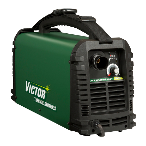
CUTMASTER 42 INTRODUCTION 2.06 Power Supply Features 120/230 VAC Power Source Air Inlet Control Panel 120V 15A 120V 20A 230V 20A Art # A-09334_AC Torch Lead Work Cable and Clamp On/Off Switch Air Inlet Power Cord Art# A-09335 Introduction Manual 0-5171... -
Page 19: Section 2Torch: Introduction
INTRODUCTION CUTMASTER 42 SECTION 2TORCH: F. Torch Ratings INTRODUCTION SL40 Torch Ratings Ambient 104° F 2T.01 Scope of Manual Temperature 40° C Duty Cycle 100% @ 40 Amps @ 193 scfh This manual contains descriptions, operating instruc- Maximum Current 40 Amps tions and maintenance procedures for the SL40 Plasma Voltage (V 500V... -
Page 20: 03 Introduction To Plasma
CUTMASTER 42 INTRODUCTION B. Gas Distribution 2T.03 Introduction to Plasma The single gas used is internally split into plasma and A. Plasma Gas Flow secondary gases. Plasma is a gas which has been heated to an ex- The plasma gas flows into the torch through the tremely high temperature and ionized so that it be- negative lead, through the starter cartridge, around comes electrically conductive. -
Page 21: Installation
INSTALLATION CUTMASTER 42 SECTION 3: INSTALLATION 3.01 Unpacking 1. Use the packing lists to identify and account for each item. A. Contents List Description Quantity CM42 Power source 10ft power input cable (installed) 120VAC Adapter Pigtail 15A 120VAC Adapter Pigtail 20A Work cable and clamp (installed) SL40 Torch (15ft(4.6m)) w/consumables Carry case... -
Page 22: Primary Input Power Connections
CUTMASTER 42 INSTALLATION 3.03 Primary Input Power Connections Power Cords Included With Power Supply Attached to the power supply is an input power cord with a 230 Volt 50 Amp NEMA 6-50P for plug. Supplied adapters allow for connection of the power supply input cable plug for when using 120V input power. Art# A-09432_AB Figure 3-1 120VAC Adapter Pigtail CAUTION... -
Page 23: Air Supply Connections
INSTALLATION CUTMASTER 42 3.04 Air Supply Connections A. Connecting Air Supply to Unit The connection is the same for compressed air or industrial compressed air in gas cylinders. 1. Connect the gas line to the compressed air inlet port at the appropriate pressure. On/Off Switch Air Inlet... -
Page 24: Power Supply Specifications
CUTMASTER 42 INSTALLATION 3.05 Power Supply Specifications CUTMASTER 42 Power Supply Specifications Input Power 120 VAC (+ - 10%), 1Phase, 50/60Hz 208-230 VAC (+ - 10%), 1Phase, 50/60Hz Output Current 20 Amps @ 120VAC, 15A 20-27 Amps @ 120VAC, 20A 20-40 Amps @ 230VAC, 20A CUTMASTER 42 Power Supply Duty Cycle (Note 1) Ambient Temperature... - Page 25 INSTALLATION CUTMASTER 42 9" (228.6mm) 120V 15A 120V 20A 230V 20A 18.5" (469.9mm) Art# A-09333_AC 7" (177mm) 26lb / 11.8kg Figure 2-1 Power Supply Dimensions & Weight NOTE Weight includes torch & leads, input power cord, and work cable with clamp. CAUTION Provide clearance for proper air flow through the power supply.
-
Page 26: Input Wiring Specifications
CUTMASTER 42 INSTALLATION 3.06 Input Wiring Specifications CUTMASTER 42 Input Power Requirements Input Power Input Current Input Current Input Suggested Sizes (See Note) Voltage Freq. (kVA) Max (Amps) Ieff (Amps) Fuse (Amps) (Volts-AC) (Hz) 1-Ph 1-Ph 1-Ph 1-Ph 50/60 27.5 50/60 15.4 50/60... -
Page 27: Section 4 System: Operation
OPERATION CUTMASTER 42 SECTION 4 SYSTEM: OPERATION 4.01 Control Panel On/Off Air Inlet Switch AC Indicator Power Cord DC Indicator (Ready) Air Indicator Overheat Indicator 120V 15A 120V 20A 230V 20A CUTMASTER ® Art# A-09338-AD The Front Panel The Rear Panel 1. -
Page 28: Preparations For Operating
CUTMASTER 42 OPERATION NOTE All consumables must be correctly installed and maintained to ensure correct operation. 4.02 Preparations For Operating At the start of each operating session: WARNING Disconnect primary power at the source before assembling or disassembling power supply, torch parts, or torch and leads assemblies. - Page 29 OPERATION CUTMASTER 42 B. Torch Connection Check that the torch is properly connected. C. Check Primary Input Power Source 1. Check the power source for proper input voltage. Make sure the input power source meets the power require- ments for the unit per Section 2, Specifications. 2.
-
Page 30: Sequence Of Operation
CUTMASTER 42 OPERATION G. Select Current Output Level Set the desired current output level. 120V 15A 120V 20A 230V 20A 27 7 4 4 0 27 7 4 4 0 120V, 15A 120V, 20A 230V, 20A A#09697_AA 4.03 Sequence of Operation The following is a typical sequence of operation for this power supply. - Page 31 OPERATION CUTMASTER 42 • Standoff Cutting With Hand Torch Art # A-09342 NOTE For best performance and parts life, always use the correct parts for the type of operation. A. The torch can be comfortably held in one hand Trigger or steadied with two hands.
- Page 32 CUTMASTER 42 OPERATION • Drag Cutting With a Hand Torch F. Place the torch tip on the work. The main arc Drag cutting works best on metal 1/4"(6 mm) thick will transfer to the work. or less. NOTE NOTE The gas preflow and postflow are a character- For best parts performance and life, always istic of the power supply and not a function use the correct parts for the type of operation.
-
Page 33: Cut Quality
OPERATION CUTMASTER 42 4.04 Cut Quality Bottom Dross Buildup Molten material which is not blown out of the cut area NOTE and resolidifies on the plate. Excessive dross may Cut quality depends heavily on setup and require secondary cleanup operations after cutting. parameters such as torch standoff, alignment Kerf Width with the workpiece, cutting speed, gas pres-... -
Page 34: General Cutting Information
CUTMASTER 42 OPERATION 4.05 General Cutting Information Left Side Cut Angle Right Side Cut Angle WARNING Disconnect primary power at the source before disassembling the power supply, torch, or torch leads. A-00512 Frequently review the Important Safety Pre- Side Characteristics Of Cut cautions at the front of this manual. -
Page 35: Theory Of Operation
THEORY OF OPERATION CUTMASTER 42 SECTION 5: THEORY OF OPERATION 5.01 Inverter Design What does the word inverter mean? The term inverter refers to the ability to change DC power into AC. Inverter power supplies immediately rectify the incoming AC to DC, and then the transistors create a higher frequency AC. The higher frequency AC then goes on to a much smaller main transformer than in a conventional power supply. - Page 36 CUTMASTER 42 THEORY OF OPERATION Notes Theory of operation Manual 0-5171...
-
Page 37: Troubleshooting
TROUBLESHOOTING CUTMASTER 42 SECTION 6: TROUBLESHOOTING 6.01 Basic Troubleshooting-Power Source Faults WARNING There are extremely dangerous voltage and power levels present inside this unit. Do not attempt to diagnose or repair it unless you are an accredited service provider and you have had training in power electronics measurement and troubleshooting techniques. - Page 38 CUTMASTER 42 TROUBLESHOOTING 3. Unit is overheated. Keep the machine plugged in and turned on for five minutes. This will allow the fan to run and cool the machine. 4. Faulty components in unit Return for repair or have qualified technician repair per service manual. E. Torch will not pilot, when torch trigger is activated. 1. Faulty parts in torch Check torch parts per section 4.02; replace as needed.
- Page 39 TROUBLESHOOTING CUTMASTER 42 3. Faulty components in unit Return for repair or have qualified technician repair per service manual. I. Cutting output is unstable or inadequate at 120V operation. 1. Low or fluctuating input voltage a. Turn output current to minimum (20 amps) and suggest using 20A Drag tip. b.
-
Page 40: Checking Unit Before Applying Power
CUTMASTER 42 TROUBLESHOOTING 3. Excessive oil or moisture in torch Hold torch 1/8 inch (3 mm) from clean surface while purging and observe oil or moisture buildup (do not activate torch). If there are contaminants in the gas, additional filtering may be needed. 4. -
Page 41: Case Removal
TROUBLESHOOTING CUTMASTER 42 6.04 Case Removal Read and follow safety information in Section 6.02 before proceeding. Remove the ten screws from the cover and remove the cover panel. Art # A-10242 6.05 Clear Cover Sheet Removal Read and follow safety information in Section 6.02 before proceeding. 1. -
Page 42: Visually Inspect
CUTMASTER 42 TROUBLESHOOTING 6.06 Visually Inspect Visually inspect the inside of the Power Source. The levels of current present in these units can cause burning or arcing of PCB, transformers, switches, or rectifier when a failure occurs. Carefully inspect all components within these units. Look in particular for the following: a) Loose or broken wires or connectors. -
Page 43: Preliminary Check Of The Main Inverter Board
TROUBLESHOOTING CUTMASTER 42 6.08 Preliminary Check of the Main Inverter Board Read and follow safety information in Section 6.02 before proceeding. Manual 0-5171 Troubleshooting... -
Page 44: Check Main On / Off Switch
CUTMASTER 42 TROUBLESHOOTING IGBT Testing Multimeter Lead Placement Diode Voltage Positive meter lead to test point 3 IGBT 1 0.2000 to 0.8000 VDC Negative meter lead to test point 2 Positive meter lead to test point 5 IGBT 2 0.2000 to 0.8000 VDC Negative meter lead to test point 4 Positive meter lead to test point 8 IGBT 3... -
Page 45: Check Pressure Switch
TROUBLESHOOTING CUTMASTER 42 6.10 Check Pressure Switch Art # A-10292 1. Pressure switch open When the pressure is up to 3.5kgf/cm (49.78 PSI), the pressure switch turns off. 2. Pressure switch closed When the pressure is less than 2.4kgf/cm (34.13 PSI), the pressure switch turns on and the resistance between 1 and 2 is about 0.1Ω. -
Page 46: Check Main Input Rectifier
CUTMASTER 42 TROUBLESHOOTING 6.12 Check Main Input Rectifier DC— Art # A-10291 Input Rectifier Testing Multimeter Lead Placement Diode Voltage Positive meter lead to AC1 AC1 to DC+ 0.2 – 0.8 VDC Negative meter lead to testpoint DC+ Positive meter lead to AC2 AC2 to DC+ 0.2 –... - Page 47 TROUBLESHOOTING CUTMASTER 42 Manual 0-5171 6-11 Troubleshooting...
- Page 48 CUTMASTER 42 TROUBLESHOOTING DC Bus Testing Multimeter Lead Placement Voltage with Supply voltage ON Positive meter lead to testpoint 30 Upper capacitor bank 192 VDC +/-10% Negative meter lead to testpoint 29 Positive meter lead to testpoint 31 Lower capacitor bank 192 VDC +/-10% Negative meter lead to testpoint 32 Positive meter lead to testpoint 29...
-
Page 49: Check Of Control Pcb
TROUBLESHOOTING CUTMASTER 42 6.14 Check of Control PCB Read and follow safety information in Section 6.02 before proceeding. Manual 0-5171 6-13 Troubleshooting... - Page 50 CUTMASTER 42 TROUBLESHOOTING Pin function signal 0VDC Control circuit power source 27VDC Negative of solenoid control signal 0VDC (when soleniod is on) Positive of solenoid control signal 27VDC Current control potentiometer 0 — 4VDC Fault indicator signal 2VDC (when indication lights up) Control circuit power supply 5VDC 0VDC...
- Page 51 TROUBLESHOOTING CUTMASTER 42 Power source of fan 24VDC 0VDC(fan negative)when fan is on 0VDC Pilot ARC current feedback signal -0.8VDC +5VDC( A main cutting arc is established) 0VDC Positive of voltage feedback Machine output + Negative of voltage feedback Machine output _ +12VDC +12VDC Pilot ARC IGBT drive signal...
-
Page 52: Waveforms
CUTMASTER 42 TROUBLESHOOTING 6.15 Waveforms 1. Vds of inverter IGBT at no load Test point C1: 4 and 5 C2: 9 and 10 (Testpoints refer to inverter PCB diagram in Sec. 6.13). Trigger Timebase Stop Positive Art # A-10247 2. Vds of inverter IGBT at full load Test point C1: 4 and 5 C2: 9 and 10 (Testpoints refer to inverter PCB diagram in Sec. -
Page 53: Main Circuit Description
TROUBLESHOOTING CUTMASTER 42 6.16 Main Circuit Description Turn off power and disconnect mains supply plug from receptacle before working on the unit. Allow two minutes for capacitors to discharge after disconnection from mains supply voltage. PFC Control Chip Art # A-10249 Manual 0-5171 6-17 Troubleshooting... - Page 54 CUTMASTER 42 TROUBLESHOOTING The mains supply voltage is connected via a double pole switch to the input rectifier U1 through an EMC filter. Over- voltage protection is provided by varistor CY1. The rectifier circuit converts the inputted AC voltage to DC voltage. The input current is controlled through being compared with reference wave.
-
Page 55: Circuit Diagram
TROUBLESHOOTING CUTMASTER 42 6.17 Circuit Diagram Art # A-09396_AF Manual 0-5171 6-19 Troubleshooting... - Page 56 CUTMASTER 42 TROUBLESHOOTING Notes Troubleshooting 6-20 Manual 0-5171...
-
Page 57: Disassembly Procedure
DISASSEMBLY PROCEDURE CUTMASTER 42 SECTION 7: DISASSEMBLY PROCEDURE 7.01 Safety Precautions for Disassembly Read and follow safety information in Section 6.02 before proceeding. Unplug unit before beginning Disassembly procedure. Manual 0-5171 Disassembly Procedure... -
Page 58: Control Board Removal
CUTMASTER 42 DISASSEMBLY PROCEDURE 7.02 Control Board Removal Read and follow safety information in Section 6.02 before proceeding with disassembly Remove case (refer to 6.04) before remove control board. Refer to graphics on page 7-3. 1. M4 Screw. Remove 4 screws from Control panel. 2. - Page 59 DISASSEMBLY PROCEDURE CUTMASTER 42 Manual 0-5171 Disassembly Procedure...
-
Page 60: Front Panel Assembly Removal
CUTMASTER 42 DISASSEMBLY PROCEDURE 7.03 Front Panel Assembly Removal Read and follow safety information in Section 6.02 before proceeding with disassembly 1. Case removal Remove the ten screws from the cover panel and remove the cover panel 2. Remove the screws on front panel 3. -
Page 61: Front Panel (Operator Interface) Circuit Board Pcb3 Removal
DISASSEMBLY PROCEDURE CUTMASTER 42 7.04 Front Panel (Operator Interface) Circuit Board PCB3 Removal Read and follow safety information in Section 6.02 before proceeding with disassembly. 1. Remove the screw on the potentiometer knob. 2. Remove the nut. 3. Remove the front panel PCB. Art # A-10252 Manual 0-5171 Disassembly Procedure... -
Page 62: Back Panel Removal
CUTMASTER 42 DISASSEMBLY PROCEDURE 7.05 Back Panel Removal Read and follow safety information in Section 6.02 before proceeding with disassembly 1. Remove screws on back panel 2. Remove the three screws 3. Terminals from supply cable. Disconnect two terminals from switch. 4. -
Page 63: Power Switch S1 And Power Cord Removal
DISASSEMBLY PROCEDURE CUTMASTER 42 7.06 Power Switch S1 and Power Cord Removal Read and follow safety information in Section 6.02 before proceeding with disassembly 1. Gas inlet. Remove gas inlet from rear panel. 2. SW locking tabs Squeeze the locking tabs and push SW out from the rear panel. 3. -
Page 64: Base Panel Removal
CUTMASTER 42 DISASSEMBLY PROCEDURE 7.07 Base Panel Removal Read and follow safety information in Section 6.02 before proceeding with disassembly 1. Remove Central Panel Screws. 2. Remove Main PCB assembly Screws. Art # A-10255 Disassembly Procedure Manual 0-5171... -
Page 65: Assembly Procedures
ASSEMBLY PROCEDURE CUTMASTER 42 SECTION 8: ASSEMBLY PROCEDURES 8.01 Installing Base Board 1. Main Power PCB assembly 2. Install main PCB assembly screws 3. Install central Panel Screws. Art # A-10256 Manual 0-5171 Assembly Procedures... -
Page 66: Installing Back Panel
CUTMASTER 42 ASSEMBLY PROCEDURES 8.02 Installing Back Panel 1. Install gas inlet. 2. Install ON/OFF switch 3. Install wire cord. 4. Reconnect Input Wire on the ON/OFF switch. 5. Install fan. 6. Install ground wire. 7. Reconnect AC Input wire on Main Power PCB to power ON/OFF switch. 8. - Page 67 ASSEMBLY PROCEDURE CUTMASTER 42 Art # A-10258 Manual 0-5171 Assembly Procedures...
-
Page 68: Installing Front Panel
CUTMASTER 42 ASSEMBLY PROCEDURES 8.03 Installing Front Panel 1. Place front panel PCB assembly into front panel. Install the nut and screw. 2. Reconnect three harnesses to control PCB. 3. Reconnect two red wires and install the screws. 4. Install the front panel screws. Art # A-10259 Assembly Procedures Manual 0-5171... -
Page 69: Installing Main Control Panel And Clear Cover Sheet
ASSEMBLY PROCEDURE CUTMASTER 42 8.04 Installing Main Control Panel and Clear Cover Sheet 1. Install 4 screws. 2. Plug harness into HF/QF connector 3. Plug harness into MB connector 4. Plug harness into SOURCE&TIP connector 5. Plug harness into DRIVE connector 6. - Page 70 CUTMASTER 42 ASSEMBLY PROCEDURES Art # A-10250 Art # A-10260 Assembly Procedures Manual 0-5171...
- Page 71 ASSEMBLY PROCEDURE CUTMASTER 42 Manual 0-5171 Assembly Procedures...
-
Page 72: Installing Case
CUTMASTER 42 ASSEMBLY PROCEDURES 8.05 Installing Case 1. Install Case. 2. Install Screws. Tighten screws. Art # A-10261 Assembly Procedures Manual 0-5171... -
Page 73: Replacement Parts
REPLACEMENT PARTS CUTMASTER 42 SECTION 9: Replacement PARTS 9.01 Introduction A. Parts List Breakdown The parts list provides a breakdown of all replaceable components. B. Returns If a product must be returned for service, contact your distributor. Materials returned without proper authoriza- tion will not be accepted. -
Page 74: Power Supply Replacement Parts
CUTMASTER 42 REPLACEMENT PARTS 9.02 Power Supply Replacement Parts Item # Description Catalog # Control PCB assembly 9-0077 Front Control PCB assembly 9-0076 Main PCB assembly 9-0079 Regulator 9-0081 Solenoid assembly 9-0082 Pressure Switch 9-0075 Front Panel with Label 9-0071 Rear Panel with Label 9-0072 Cover with Labels... -
Page 75: Sl40 Torch Replacement Parts
REPLACEMENT PARTS CUTMASTER 42 9.03 SL40 Torch Replacement Parts Item # Qty. Description Catalog # SL40 Torch w/15ft(4.6m) leads, (not shown) 7-0040 Handle Kit (not shown) 9-0089 Microswitch 9-7031 Electrode 9-0096 Start Cartridge 9-0097 Tip, 40A Standoff 9-0094 Tip, 40A Drag 9-0093 Tip, 20A Drag 9-0091 Shield Cup 9-0098... -
Page 76: Optional Accessories
CUTMASTER 42 REPLACEMENT PARTS 9.04 Optional Accessories Description Cat. No. Standoff Guide for SL40 9-0090 Cutting Guide Bushing, 7-2915 accommodating the use of the SL40 with the cutting guides Torch Cutting Guides / Guides Kits including Carrying Case, Radius/Roller Kit (7-7501), Circle Cutting Guide (7- 7-8910 3291), Magnetic Pivot, Suction Pivot Circle Cutting Guide Kit, 7-3291 Radius/Roller Cutting Guide Kit 7-7501 Filter Body, single stage air filter 7-7507... -
Page 77: Appendix 1
APPENDIx CUTMASTER 42 APPENDIX 1: SL40 TORCH PIN-OUT DIAGRAM A. Hand Torch Pin-Out Diagram ATC Male Connector Cutmaster 42 Female Torch Receptacle Front View Front View Negative / Plasma Negative / Plasma 4 - Green / 8 - Open 8 - Ground Torch/PIP switches 4 - Torch/PIP switch input... - Page 78 THE AMERICAS Denton, TX USA U.S. Customer Care Ph: 1-800-426-1888 (tollfree) Fax: 1-800-535-0557 (tollfree) International Customer Care Ph: 1-940-381-1212 Fax: 1-940-483-8178 Miami, FL USA Sales Office, Latin America Ph: 1-954-727-8371 Fax: 1-954-727-8376 Oakville, Ontario, Canada Canada Customer Care Ph: 1-905-827-4515 Fax: 1-800-588-1714 (tollfree) EUROPE Chorley, United Kingdom...
Need help?
Do you have a question about the 42 CUTMASTER and is the answer not in the manual?
Questions and answers