Table of Contents
Advertisement
Advertisement
Table of Contents

Related Manuals for MasterCraft MIG


Summary of Contents for MasterCraft MIG
- Page 1 INSTRUCTION MANUAL MIG/FLUX-CORE WIRE FEED WELDER KIT 058-8195-2...
- Page 2 Keep this instruction manual for future use. Should this product be passed on to a third party, then this instruction manual must be included. MIG/FLUX-CORE WIRE FEED WELDER KIT 058-8195-2...
- Page 3 Setting the wire tension Press the trigger on the gun. Turn the drive tension adjustment knob (1) clockwise, and increase the drive tension until the wire seems to feed smoothly without slipping. page 18, steps 1-2 MC-588195-24 MIG/FLUX-CORE WIRE FEED WELDER KIT 058-8195-2...
- Page 4 STEP 3 Operation Hold the torch in one hand and turn the wire speed dial with the other hand to its maximum position. Pull the trigger (1) on the torch to start an arc. Drag the torch toward the user while simultaneously turning the wire speed dial counterclockwise.
- Page 5 QUICK START GUIDE TECHNICAL SPECIFICATIONS SAFETY GUIDELINES 4–8 KEY PARTS DIAGRAM IMPORTANT INFORMATION 10–13 ASSEMBLY INSTRUCTIONS 14–18 OPERATING INSTRUCTIONS 19–27 MAINTENANCE TROUBLESHOOTING 29–30 MAIN CIRCUIT CHART EXPLODED VIEW PARTS LIST WARRANTY 34–35 MIG/FLUX-CORE WIRE FEED WELDER KIT 058-8195-2...
- Page 6 For metal thickness Use wire size 20-gauge-5/32" 0.03" (1/32") 0.8 mm Flux core Steel 5/128-5/32" 0.035" (5/128") 0.9 mm 1.0-4.0 mm 20-gauge-1/8" 0.03" (1/32") 0.8 mm Steel, Stainless steel 5/128-1/8" 0.023" (3/128") 0.6 mm 1.0-3.0 mm MIG/FLUX-CORE WIRE FEED WELDER KIT 058-8195-2...
- Page 7 PERSONAL SAFETY These precautions are intended for the personal safety of the user and others working with the user. Please take time to read and understand them. MIG/FLUX-CORE WIRE FEED WELDER KIT 058-8195-2...
- Page 8 ¼". Risk of burns: Do not touch the welded materials with bare hands, as the • welded materials are hot and can cause severe burns MIG/FLUX-CORE WIRE FEED WELDER KIT 058-8195-2...
- Page 9 Risk of explosion: Keep high pressure shielding gas cylinder away from • welding or electrical circuits. Do not touch the cylinder with MIG gun and do not weld on the cylinder. Use proper regulators, gas hoses, and fittings for the specific application.
- Page 10 Do not allow the user to drape cables over or around the body. • Do not point MIG gun toward the user or other personnel. • Do not allow a person to use electronic devices such as pacemakers in the welding area.
- Page 11 Potential hazard that may result in moderate injury or damage to equipment. • Do not operate the welder if the output cable electrode, MIG gun, wire or wire feed system is wet. All the components and the welder must be completely dry before attempting to use the welder.
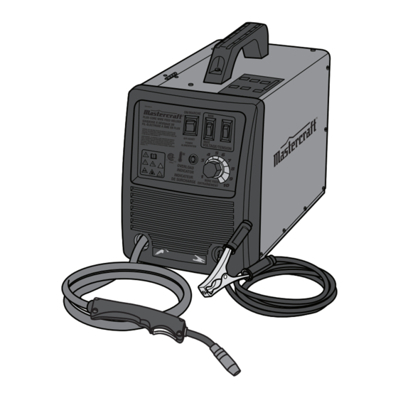
- Page 12 MC-588195-01 Description Description MIN/MAX voltage setting MIG torch 1/2 voltage setting Thermal overload indicator Wire feed setting ON/OFF switch Ground cable and clamp MIG/FLUX-CORE WIRE FEED WELDER KIT 058-8195-2...
- Page 13 ® The Mastercraft portable and gasless MIG/Flux-Core Wire Feed Welder Kit uses AC single phase 120V, 60 Hz/20A with a time delayed fuse or circuit breaker. The kit provides two heat settings, infinite wire speed control, overload and thermal protection. The welder kit can be used for welding mild steel 20 gauge to 1/8"...
- Page 14 Welding Cable and MIG gun/torch The welding wire is driven through the welding cable and the MIG gun/torch to the workpiece. It is attached to the drive system and the gun trigger activates the drive motor.
-
Page 15: Gas Selection
Gas selection Different materials require different shielding gas when MIG welding. Refer to the set up chart inside the wire drive compartment. Mild steel: Use 75% Argon and 25% for reduced spatter and reduced penetration for thinner materials. - Page 16 Wire drive compartment The wire drive compartment has wire feed components (1) such as wire feeder and spool hub, and a set up chart (2). MC-588195-25 MIG/FLUX-CORE WIRE FEED WELDER KIT 058-8195-2...
-
Page 17: Assembly Instructions
Note: If the wire is already installed in the welder, roll the wire back onto the wire spool by manually rotating the wire spool clockwise. Do not allow the wire to come out of rear end of the inlet guide tube. MIG/FLUX-CORE WIRE FEED WELDER KIT 058-8195-2... - Page 18 Note: When installing the drive roller, the number stamped on the drive roller should face the user. Push the drive roller onto the drive roller shaft. 6. Reinstall the drive roller cap and lock in place by turning it clockwise. Close the wire drive compartment. MIG/FLUX-CORE WIRE FEED WELDER KIT 058-8195-2...
- Page 19 • Do not weld metal thinner than 18 gauge, as doing so may burn the metal. • Before installing, remove any old wire from the MIG gun assembly to prevent the wire from being jammed inside the gun liner. •...
- Page 20 Refer to the set up chart on the back side of the wire drive compartment. 14. Set the wire speed control Straighten the MIG gun cable and pull the trigger in the gun handle to feed the wire through the torch assembly MIG/FLUX-CORE WIRE FEED WELDER KIT 058-8195-2...
- Page 21 1. Press the trigger on the gun. 2. Turn the drive tension adjustment knob fig G (1) clockwise, and increase the drive tension until the wire seems to feed (fig G) smoothly without slipping MC-588195-24 MIG/FLUX-CORE WIRE FEED WELDER KIT 058-8195-2...
- Page 22 ¼". Tuning in the wire speed: This is one of the most important parts of the MIG welder operation and must be done before starting each welding job or whenever any of the following variables are changed: heat setting, wire diameter, or wire type.
- Page 23 Use the wire feed control to slightly increase or decrease the heat and penetration by selecting higher or lower wire feed settings. Repeat this tune-in procedure if a new heat setting, a different diameter wire, or a different type of welding wire is selected. MIG/FLUX-CORE WIRE FEED WELDER KIT 058-8195-2...
-
Page 24: Welding Techniques
Likewise, if the travel speed is slow, the penetration will be deep and the finished weld bead will be high and wide. MIG/FLUX-CORE WIRE FEED WELDER KIT 058-8195-2... - Page 25 The weave bead is made by weaving the travelling with the torch in a straight wire from side to side while moving with (fig M) line while keeping the wire and nozzle the torch (fig L) centered over the weld joint MIG/FLUX-CORE WIRE FEED WELDER KIT 058-8195-2...
-
Page 26: Welding Position
For this position, angle B should be zero and MC-588195-17 angle A will vary from 45 to 60 degrees (fig P) to provide better puddle control MIG/FLUX-CORE WIRE FEED WELDER KIT 058-8195-2... - Page 27 (fig Q) the nozzle Angle B should be zero degrees so that the wire is aiming directly into the weld joint. If excessive dripping of the weld MC-588195-18 puddle occurs, select a lower heat setting. MIG/FLUX-CORE WIRE FEED WELDER KIT 058-8195-2...
-
Page 28: Multiple Pass Welding
The sequence of lying multiple pass beads into a T fillet joint and a lap fillet joint is shown T Join in Three Passes (fig S) MC-588195-20 MIG/FLUX-CORE WIRE FEED WELDER KIT 058-8195-2... -
Page 29: Spot Welding
Select the wire diameter, heat setting, and tune in the wire speed in such a way suitable for welding the material with a (fig V) continuous bead MC-588195-23 MIG/FLUX-CORE WIRE FEED WELDER KIT 058-8195-2... - Page 30 5. Make practice spot welds on scrap metal and vary the duration of time of holding the trigger until a desired spot weld is made. 6. Make spot welds on the actual workpiece at desired locations. MIG/FLUX-CORE WIRE FEED WELDER KIT 058-8195-2...
- Page 31 Store the welder in a clean and dry location away from corrosive gas and excess dust at a temperature of 10°F 120°F and relative humidity of less than 90%. • It is recommended to repack the welder when transporting or storing the welder after use. • Cleaning is required before storage. MIG/FLUX-CORE WIRE FEED WELDER KIT 058-8195-2...
-
Page 32: Troubleshooting
1. Use the correct wire. 2. Base metal not grounded 2. Make sure the connection is good. Arc is hard to start. properly. If the problem persists, send it for servicing or return back to the store. MIG/FLUX-CORE WIRE FEED WELDER KIT 058-8195-2... - Page 33 Inconsistent arc or loose. wire feed. 3. Contact tip worn or wrong size. 3. Replace the contact tip. 4. Rusty or corroded wire. 4. Replace the wire. Note: For further repair information, please call 1-800-689-9928. MIG/FLUX-CORE WIRE FEED WELDER KIT 058-8195-2...
- Page 34 Welding gun switch Welding gun Earth champ NO GAS MC-588195-24 MIG/FLUX-CORE WIRE FEED WELDER KIT 058-8195-2...
- Page 35 MC-588195-25 MIG/FLUX-CORE WIRE FEED WELDER KIT 058-8195-2...
- Page 36 Wire feeder MIN/MAX 1/2 voltage switch Fan blade ON/OFF switch Handle Overload indicator Right panel MIG torch Power cord If any parts are missing or damaged, or if you have any questions, please call 1-800-689-9928. MIG/FLUX-CORE WIRE FEED WELDER KIT 058-8195-2...
- Page 37 This warranty will not apply to any product or part thereof if any part from another manufacturer is installed therein or any repairs or alterations have been made or attempted by unauthorized persons. MIG/FLUX-CORE WIRE FEED WELDER KIT 058-8195-2...
- Page 38 This warranty gives you specific legal rights, and you may have other rights, which may vary from province to province. The provisions contained in this warranty are not intended to limit, modify, take away from, disclaim, or exclude any statutory warranties set forth in any applicable provincial or federal legislation. MIG/FLUX-CORE WIRE FEED WELDER KIT 058-8195-2...
Need help?
Do you have a question about the MIG and is the answer not in the manual?
Questions and answers