Table of Contents
Advertisement
Advertisement
Table of Contents

Related Manuals for MasterCraft 058-8194-4


Summary of Contents for MasterCraft 058-8194-4
- Page 1 INSTRUCTION MANUAL FLUX-CORE WIRE FEED WELDER KIT 058-8194-4...
- Page 2 Keep this instruction manual for future use. Should this product be passed on to a third party, then this instruction manual must be included. FLUX-CORE WIRE FEED WELDER KIT 058-8194-4...
- Page 3 Setting wire tension Press the trigger on the gun. Turn the drive tension adjustment knob (1) clockwise, and increase the drive tension until the wire seems to feed smoothly without slipping. page 17 MC-588194-08 FLUX-CORE WIRE FEED WELDER KIT 058-8194-4...
- Page 4 STEP 3 Operation Hold the torch in one hand, and allow the nozzle to rest on the edge of the workpiece farther from the user. Turn the wire speed dial with the other hand to its maximum position and continue to hold onto the knob. Pull the trigger (1) on the torch to start an arc.
- Page 5 QUICK START GUIDE TECHNICAL SPECIFICATIONS SAFETY GUIDELINES 4–8 KEY PARTS DIAGRAM IMPORTANT INFORMATION 10–12 ASSEMBLY INSTRUCTIONS 13–17 OPERATING INSTRUCTIONS 18–26 MAINTENANCE TROUBLESHOOTING 28–29 MAIN CIRCUIT CHART EXPLODED VIEW PARTS LIST WARRANTY 33–34 FLUX-CORE WIRE FEED WELDER KIT 058-8194-4...
- Page 6 30-65 A (Peak 125 A) DUTY CYCLE 20% @ 65 A WIRE USED Flux-core wire WIRE DIAMETER 0.023", 0.030", 0.035" DIMENSIONS (L x W x H) 17.6" x 9.4" x 14.5" (21 kg) WEIGHT 46 lb 5 oz FLUX-CORE WIRE FEED WELDER KIT 058-8194-4...
- Page 7 PERSONAL SAFETY These precautions are intended for the personal safety of the user and others working with the user. Please take time to read and understand them. FLUX-CORE WIRE FEED WELDER KIT 058-8194-4...
- Page 8 ¼". Risk of burns: Do not touch the welded materials with bare hands, as the • welded materials are hot and can cause severe burns FLUX-CORE WIRE FEED WELDER KIT 058-8194-4...
- Page 9 Risk of UV and IR arc rays: Do not look at the welding arc without proper eye • protection, as the welding arc produces ultraviolet (UV) and infrared (IR) rays. Use screens or other barriers to protect other personnel from the rays. FLUX-CORE WIRE FEED WELDER KIT 058-8194-4...
- Page 10 Do not point MIG gun toward the user or other personnel. • Do not allow a person to use electronic devices such as pacemakers in the welding area. • Consult a doctor before using any electric arc welder or cutting device. FLUX-CORE WIRE FEED WELDER KIT 058-8194-4...
- Page 11 Note: Recycle the unwanted materials rather than disposing of it as waste. Sort the tools, hoses, and packaging in specific categories and take to the local recycling center or dispose of it in an environmentally safe way. FLUX-CORE WIRE FEED WELDER KIT 058-8194-4...
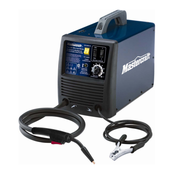
- Page 12 MC-588194-04 Description Description MIN/MAX voltage setting MIG gun 1/2 voltage setting Thermal overload indicator Wire speed setting ON/OFF switch Ground cable and clamp FLUX-CORE WIRE FEED WELDER KIT 058-8194-4...
- Page 13 Two voltage adjustment switches are provided on the front panel of the welder kit. Refer to the set up chart for initial adjustment of the voltage setting. Wire feed setting This setting adjusts the wire feed speed. FLUX-CORE WIRE FEED WELDER KIT 058-8194-4...
- Page 14 Power cord The power cord connects the welder to the 120 V power supply. Connect the 15 A plug into a 120 V/20 A receptacle to supply power to the welder. FLUX-CORE WIRE FEED WELDER KIT 058-8194-4...
- Page 15 Wire drive compartment The wire drive compartment has wire feed components (1) such as wire feeder and spool hub, and a set up chart (2). MC-588194-23 FLUX-CORE WIRE FEED WELDER KIT 058-8194-4...
-
Page 16: Assembly Instructions
Note: If the wire is already installed in the welder, roll the wire back onto the wire spool by manually rotating the wire spool clockwise. Do not allow the wire to come out of rear end of the inlet guide tube. FLUX-CORE WIRE FEED WELDER KIT 058-8194-4... - Page 17 Note: When installing the drive roller, the number stamped on the drive roller should face the user. Push the drive roller onto the drive roller shaft. 6. Reinstall the drive roller cap and lock in place by turning it clockwise. Close the wire drive compartment. FLUX-CORE WIRE FEED WELDER KIT 058-8194-4...
- Page 18 2. Ensure proper groove on the drive roller is in place for the wire to be installed. 3. Remove the packaging from the wire spool and identify the leading end of the wire secured on the edge of the spool. FLUX-CORE WIRE FEED WELDER KIT 058-8194-4...
- Page 19 13. Plug in and turn the welder ON. Set the voltage switch to the voltage setting recommended for the gauge of metal that is to be welded. Refer to the set up chart on the back side of the wire drive compartment. FLUX-CORE WIRE FEED WELDER KIT 058-8194-4...
- Page 20 1. Press the trigger on the gun. 2. Turn the drive tension adjustment knob fig G (1) clockwise, and increase the drive tension until the wire seems to feed (Fig G) smoothly without slipping MC-588194-08 FLUX-CORE WIRE FEED WELDER KIT 058-8194-4...
- Page 21 There are two angles of the torch nozzle in relation to the workpiece that must be considered when welding. FLUX-CORE WIRE FEED WELDER KIT 058-8194-4...
- Page 22 Use the wire feed control to slightly increase or decrease the heat and penetration by selecting higher or lower wire feed settings. Repeat this tune-in procedure if a new heat setting, a different diameter wire, or a different type of welding wire is selected. FLUX-CORE WIRE FEED WELDER KIT 058-8194-4...
-
Page 23: Welding Techniques
Likewise, if the travel speed is slow, the penetration will be deep and the finished weld bead will be high and wide. FLUX-CORE WIRE FEED WELDER KIT 058-8194-4... - Page 24 The weave bead is made by weaving the travelling with the torch in a straight wire from side to side while moving with (fig M) line while keeping the wire and nozzle the torch (fig L) centered over the weld joint FLUX-CORE WIRE FEED WELDER KIT 058-8194-4...
-
Page 25: Welding Position
For this position, angle B should be zero and MC-588194-17 angle A will vary from 45 to 60 degrees (fig P) to provide better puddle control FLUX-CORE WIRE FEED WELDER KIT 058-8194-4... - Page 26 (fig Q) the nozzle Angle B should be zero degrees so that the wire is aiming directly into the weld joint. If excessive dripping of the weld MC-588194-18 puddle occurs, select a lower heat setting. FLUX-CORE WIRE FEED WELDER KIT 058-8194-4...
-
Page 27: Multiple Pass Welding
T Join in Three Passes produce strong joint. The sequence of lying multiple pass beads into a T fillet joint and a lap fillet joint is shown MC-588194-20 (fig S) FLUX-CORE WIRE FEED WELDER KIT 058-8194-4... -
Page 28: Spot Welding
Select the wire diameter, heat setting, and tune in the wire speed in such a way suitable for welding the material with a (fig V) continuous bead MC-588194-23 FLUX-CORE WIRE FEED WELDER KIT 058-8194-4... - Page 29 5. Make practice spot welds on scrap metal and vary the duration of time of holding the trigger until a desired spot weld is made. 6. Make spot welds on the actual workpiece at desired locations. FLUX-CORE WIRE FEED WELDER KIT 058-8194-4...
- Page 30 10° F 120° F and relative humidity of less than 90%. • It is recommended to repack the welder when transporting or storing the welder after use. • Cleaning is required before storage. FLUX-CORE WIRE FEED WELDER KIT 058-8194-4...
-
Page 31: Troubleshooting
1. Use the correct wire. 2. Base metal not grounded 2. Make sure the connection is good. Arc is hard to start. properly. If the problem persists, send it for servicing or return back to the store. FLUX-CORE WIRE FEED WELDER KIT 058-8194-4... - Page 32 Inconsistent arc or loose. wire feed. 3. Contact tip worn or wrong size. 3. Replace the contact tip. 4. Rusty or corroded wire. 4. Replace the wire. Note: For further repair information, please call 1-800-689-9928. FLUX-CORE WIRE FEED WELDER KIT 058-8194-4...
- Page 33 Welding gun switch Earth champ Welding gun MC-588194-22 FLUX-CORE WIRE FEED WELDER KIT 058-8194-4...
- Page 34 FLUX-CORE WIRE FEED WELDER KIT 058-8194-4...
- Page 35 MC-588194-23 FLUX-CORE WIRE FEED WELDER KIT 058-8194-4...
- Page 36 Main transformer Wire feeder Fan bracket MIN/MAX 1/2 voltage switch ON/OFF switch Fan blade Overload indicator Handle MIG torch If any parts are missing or damaged, or if you have any questions, please call 1-800-689-9928. FLUX-CORE WIRE FEED WELDER KIT 058-8194-4...
- Page 37 This warranty will not apply to any product or part thereof if any part from another manufacturer is installed therein or any repairs or alterations have been made or attempted by unauthorized persons. FLUX-CORE WIRE FEED WELDER KIT 058-8194-4...
- Page 38 This warranty gives you specific legal rights, and you may have other rights, which may vary from province to province. The provisions contained in this warranty are not intended to limit, modify, take away from, disclaim, or exclude any statutory warranties set forth in any applicable provincial or federal legislation. FLUX-CORE WIRE FEED WELDER KIT 058-8194-4...
Need help?
Do you have a question about the 058-8194-4 and is the answer not in the manual?
Questions and answers