Table of Contents
Advertisement
USERS MANUAL / GEBRUIKERSHANDLEIDING / BETRIEBSANLEITUNG
MANUEL UTILISATEUR / MANUAL DE UTILIZACION / INSTRUZIONI PER L'USO
MASTERVOLT
Snijdersbergweg 93,
1105 AN Amsterdam
The Netherlands
Tel.: +31-20-3422100
Fax.: +31-20-6971006
www.mastervolt.com
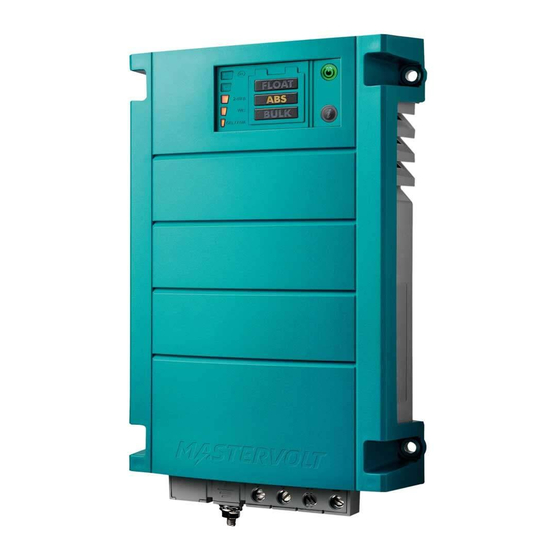
ChargeMaster
12/25-3, 24/12-3
FULL AUTOMATIC BATTERY CHARGER
ENGLISH:
NEDERLANDS:
DEUTSCH:
FRANÇAIS:
CASTELLANO:
ITALIANO:
Copyright © 2010 Mastervolt v 1.0 February 2010
PAGE 1
PAGINA 21
SEITE 41
PAGINA 61
PÁGINA 81
PÁGINA 101
Advertisement
Table of Contents

Related Manuals for Mastervolt ChargeMaster 12/25-3


Summary of Contents for Mastervolt ChargeMaster 12/25-3
- Page 1 FULL AUTOMATIC BATTERY CHARGER MASTERVOLT ENGLISH: PAGE 1 Snijdersbergweg 93, NEDERLANDS: PAGINA 21 1105 AN Amsterdam DEUTSCH: SEITE 41 The Netherlands FRANÇAIS: PAGINA 61 Tel.: +31-20-3422100 CASTELLANO: PÁGINA 81 Fax.: +31-20-6971006 ITALIANO: PÁGINA 101 www.mastervolt.com Copyright © 2010 Mastervolt v 1.0 February 2010...
-
Page 2: Table Of Contents
How to set up a MasterBus network......................... 11 MasterBus functions............................12 TROUBLE SHOOTING ..............................16 Fault finding table ............................. 16 TECHNICAL DATA................................ 17 Specifications ..............................17 Dimensions............................... 18 Characteristics..............................19 ORDERING INFORMATION............................20 EC DECLARATION OF CONFORMITY ........................20 February 2010 / Chargemaster 12/25-3, 24-12-3 / EN... -
Page 3: General Information
(carefully) follow • possible errors in the manuals and the results thereof. the procedures. CAUTION! Special data, restrictions and rules with regard to preventing damage. procedure, circumstance, which deserves extra attention. EN / Chargemaster 12/25-3, 24-12-3 / February 2010... -
Page 4: Important Safety Instructions
Use of an attachment or spare part not recommended WARNING – RISK EXPLOSIVE GASES. or sold by Mastervolt may result in a risk of fire, WORKING IN VICINITY OF A LEAD-ACID BATTERY electric shock, or injury to persons. DANGEROUS. BATTERIES GENERATE... -
Page 5: Warnings Regarding The Use Of Batteries
NEVER charge a frozen battery. 10 Excessive battery discharge and/or high charging voltages can cause serious damage to batteries. Do not exceed the recommended limits of discharge level of your batteries. EN / Chargemaster 12/25-3, 24-12-3 / February 2010... -
Page 6: Operation
Power LED blinks red. ABSORPTION BULK FLOAT CAUTION! The Chargemaster is not protected against: • reversing polarity of the DC-output, CHARGE CURRENT • three phase AC connection. TIME Figure 3: Three step charge system February 2010 / Chargemaster 12/25-3, 24-12-3 / EN... -
Page 7: Temperature Compensated Charging
The segment position temperatures. indicates failure cause. section explanation. CAUTION! The Chargemaster is not protected against: • reversing polarity of the DC-output, • three phase AC on the AC-input. EN / Chargemaster 12/25-3, 24-12-3 / February 2010... -
Page 8: Installation
(PE / GND) to the hull or the chassis. CAUTION! For safe installation it is necessary to Insert a Residual Current Device (earth leakage switch) in the AC input circuit of the Chargemaster. February 2010 / Chargemaster 12/25-3, 24-12-3 / EN... -
Page 9: Overview Connections
Chargemaster, the cabling and/or the terminal connections. Fuses between the batteries and the Chargemaster can not prevent damage caused by reversed polarity. Reverse polarity damage detectable service department and not covered by the warranty. EN / Chargemaster 12/25-3, 24-12-3 / February 2010... -
Page 10: Commissioning/Decommissioning
Avoid having flammable materials Always use the original packing for transportation. Contact close by. your local Mastervolt Service Centre for further details if you want to return the apparatus for repair. February 2010 / Chargemaster 12/25-3, 24-12-3 / EN... -
Page 11: Masterbus
MasterBus is formed. Keep the following rules in mind: Do not make T-connections in the network. Place a terminating device on both network ends. Terminating Terminating device device EN / Chargemaster 12/25-3, 24-12-3 / February 2010... -
Page 12: History
Lowest detected DC voltage output 1 Highest voltage Highest detected DC voltage output 1 Output 2 Lowest voltage Lowest detected DC voltage output 2 Highest voltage Highest detected DC voltage output 2 Output 3 February 2010 / Chargemaster 12/25-3, 24-12-3 / EN... -
Page 13: Configuration
0-16.00/0-32.00V Alarm delay Alarm delay time 30sec 0-240sec Traction Traction Bulk Traction bulk voltage +300/+600mV 0-1200mV Traction Absorpt Traction absorption voltage +300/+600mV 0-1200mV Traction absorpt Traction absorption timer 8 hrs (Read only) February 2010 / Chargemaster 12/25-3, 24-12-3 / EN... - Page 14 4th yellow LED from bottom of the MasterView Read Out illuminates (see manual MasterView Read Out) Led 5 Top yellow LED of the MasterView Read Out illuminates (see manual MasterView Read Out) February 2010 / Chargemaster 12/25-3, 24-12-3 / EN...
- Page 15 Command to start the Bulk state of charge Command to start the Absorption state of charge Float Command to start the Float state of charge State Command to switch on the ChargeMaster EN / Chargemaster 12/25-3, 24-12-3 / February 2010...
-
Page 16: Trouble Shooting
Batteries are too warm, Defective battery (short circuit in cell) Check battery and replace if necessary. gassing Battery temperature too high Use the battery temperature sensor. Charge voltage too high Check settings (see section 5.3.4). February 2010 / Chargemaster 12/25-3, 24-12-3 / EN... -
Page 17: Technical Data
<50dBA / 1m <50dBA / 1m Protection degree IP23 IP23 Approvals Fully CE and E-marking according to Fully CE and E-marking according to automotive directive 95/54/EG. automotive directive 95/54/EG. Communication Full MasterBus Full MasterBus EN / Chargemaster 12/25-3, 24-12-3 / February 2010... -
Page 18: Dimensions
TECHNICAL DATA DIMENSIONS Figure 13: Dimensions in mm [inch] February 2010 / Chargemaster 12/25-3, 24-12-3 / EN... -
Page 19: Characteristics
336 hr timer: 8 hr bulk timer = current Figure 15: Charge characteristic of the three-step Plus charging method (at 25°C / 77°F) Figure 16: Temperature compensation characteristic (charge voltage versus temperature) EN / Chargemaster 12/25-3, 24-12-3 / February 2010... -
Page 20: Ordering Information
Battery temperature sensor, incl. 15 metres / 49 ft cable 77040000 MasterBus Terminator Mastervolt offers a wide range of products for your electrical installation, AGM, Gel and Li-ion batteries, shore power connections, DC distribution kits and many more. 9 EC DECLARATION OF CONFORMITY...
Need help?
Do you have a question about the ChargeMaster 12/25-3 and is the answer not in the manual?
Questions and answers