
Related Manuals for Mastervolt CHARGEMASTER 12/35-3


Summary of Contents for Mastervolt CHARGEMASTER 12/35-3
- Page 1 USERS MANUAL CHARGEMASTER 12/35-3, 12/50-3, 24/20-3, 24/30-3 FULL AUTOMATIC BATTERY CHARGER...
- Page 2 TABLE OF CONTENTS TABLE OF CONTENTS: 10000008586/00 - February 2015 GENERAL INFORMATION .............................. 3 Use of this manual .............................. 3 Validity of this manual ............................3 Use of pictograms .............................. 3 Identification label ...............................
-
Page 3: General Information
Important Safety Instructions. Copyright © 2014 Mastervolt. All rights reserved. Reproduction, transfer, distribution or storage of part or all of the contents in this document in any form without the... -
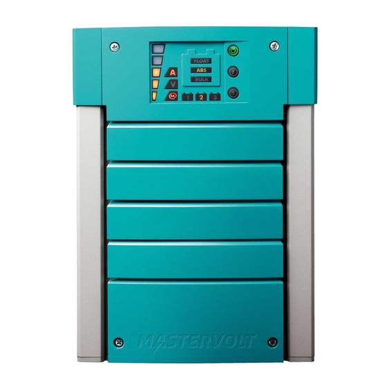
Page 4: Operation
Figure 2: operation of the ChargeMaster FEATURES SWITCHING ON / STAND-BY The Mastervolt ChargeMaster is a fully automatic battery The ChargeMaster is activated by holding the POWER charger. This means that under normal circumstances it switch pressed for approx. 5 seconds. The POWER switch may stay switched on with the AC power and batteries will illuminate green. -
Page 5: Led Display
OPERATION Load bar Yellow LED “A” = on Yellow LED “V” = on Actual stage of the three step charge algorithm. Charge voltage Charge current 100% >14V >28V 13-14V 26-28V 12-13V 24-26V 11-12V 22-24V 10.5-11V, 21-22V, Blinking: Blinking: 20-21V 10-10,5V Selected battery bank Red LED: see section 2.7 (1, 2 or 3). -
Page 6: Three Step Charge Algorithm
OPERATION THREE STEP CHARGE ALGORITHM 2.4.1 Temperature compensated charging By installing the battery temperature sensor the charge See Figure 4. Battery charging is accomplished in three voltages automatically adapted deviating automatic stages: BULK, ABSORPTION and FLOAT. temperatures. The first step of the three step charge system is the BULK phase, in which the output current of the charger is 100%, and the greater part of the capacity of the battery is rapidly charged. -
Page 7: Masterbus (Optional)
If a fault communication between the different Mastervolt system condition occurs, a load bar segment on the display devices such as the inverter, battery charger, generator, illuminates red. The LED position indicates the failure batteries and many more. -
Page 8: Installation
INSTALLATION 3 INSTALLATION During installation commissioning Although the ChargeMaster fully complies with all ChargeMaster, the important safety instructions are applicable EMC limits, it may still cause harmful applicable at all times. interference to radio communication equipment. If such interference appears, it is recommended to increase the separation between the ChargeMaster and the UNPACKING equipment, to relocate the receiving antenna or to... -
Page 9: Batteries
The minimum required battery capacity for negative post of the battery bank or the ground side of a Mastervolt gel batteries (MVG series) is as follows: current shunt. Do not use the chassis frame as the negative conductor. Tighten securely. The positive battery... -
Page 10: Overview Connection Compartment
INSTALLATION OVERVIEW CONNECTION COMPARTMENT 1 2 3 1. Cable gland for AC-wiring 6. Positive terminal charge output 2 2. Isolation caps for DC connections 7. Positive terminal charge output 3 3. Positive terminal charge output 1 8. MasterBus connectors 4. Common negative output terminal 9. - Page 11 INSTALLATION 3.7.2 Connection example AC Input DC fuse Battery fuse Battery Battery fuse fuse Temperature sensor BATTERY BATTERY BATTERY BANK 1 BANK 2 BANK 3 This schematic is to illustrate the general placement of the ChargeMaster in a circuit. It is not meant to provide detailed wiring instructions for any particular electrical installation.
-
Page 12: Installation Step By Step
INSTALLATION INSTALLATION STEP BY STEP Fix the enclosure to the wall by fastening two screws at the lower side of the enclosure as well. Mark the position of the four mounting spots by using the mounting bracket. Then fix the mounting bracket to the wall. - Page 13 INSTALLATION If required, change DIP-settings. See section Mount the isolation caps of the DC terminals back into position 4.1 for adjustment. Mind the + and – markings! Use a small screw driver for adjustment of the DIP-switches. Attach the battery temperature sensor to the casing of battery bank 1.
-
Page 14: Commissioning After Installation
When placing this fuse, a spark can occur, Always use the original packing for transportation. Contact caused by the capacitors used in the your local Mastervolt Service Centre for further details if ChargeMaster. This is particularly dangerous you want to return the apparatus for repair. -
Page 15: Settings
SETTINGS 4 SETTINGS Adjustment of the settings of the ChargeMaster can be 4.1.4 DIP switch 4: CEC Energy saving mode made in two different ways: By means of DIP-switches; see section 4.1; Energy saving mode disabled (factory setting) Via the MasterBus network;... -
Page 16: Masterbus Functions
SETTINGS MASTERBUS FUNCTIONS The equalizing mode can only be started when the Adjustment of the settings of the ChargeMaster can be ChargeMaster is in operation and in Float mode. The made via the MasterBus network (by means of a remote equalize mode can only be started by means of MasterBus control panel or an interface connected to a PC with (see section 4.3.4). - Page 17 SETTINGS Value Meaning Factory setting Adjustable range Lowest DC volt Lowest detected DC voltage output 2 (read only) Highest DC Volt Highest detected DC voltage output 2 (read only) Battery 3 Lowest DC volt Lowest detected DC voltage output 3 (read only) Highest DC Volt Highest detected DC voltage output 3...
- Page 18 SETTINGS Value Meaning Factory setting Adjustable. range DC High off Lower threshold level to stop the Output high alarm 15.50/31.00V 0-16.00/0-32.00V DC Low on Lower threshold level to trigger the Output low alarm 10.00/20.00V 0-16.00/0-32.00V DC Low off Upper threshold level to stop the Output low alarm 11.00/22.00V 0-16.00/0-32.00V Alarm Delay...
- Page 19 SETTINGS Value Meaning Factory setting Adjustable. range Events Event x source Disabled (See List of event Event-based command Event by the ChargeMaster that should result in an sources, section action by another device on the MasterBus network. 4.3.6) Event x target (See Device list) Event-based command Selection of device on the MasterBus network that...
-
Page 20: Trouble Shooting
If you cannot solve a problem with the aid of this chapter, contact your local Mastervolt Service Centre. Make sure you have the following information present if you have to contact your local Mastervolt Service Center to solve a problem: ... -
Page 21: Technical Data
TECHNICAL DATA 6 TECHNICAL DATA SPECIFICATIONS 12V MODELS Model 12/35-3 12/50-3 Article no. 44010350 44010500 GENERAL Nominal input voltage**: 120/230V 120/230V Nominal input frequency: 50/60Hz 50/60Hz Full load consumption: 575VA 825VA Efficiency at full load (230V AC): ≥81% @ 230V input ≥81% @ 230V input Nominal output voltage: Total maximum charge current (I... -
Page 22: Specifications 24V Models
TECHNICAL DATA SPECIFICATIONS 24V MODELS Model 24/20-3 24/30-3 Article no. 44020200 44020300 GENERAL Nominal input voltage**: 120/230V 120/230V Nominal input frequency: 50/60Hz 50/60Hz Full load consumption: 660VA 925VA Efficiency at full load: ≥83% @ 120V input ≥85% @ 230V input Nominal output voltage: Total maximum charge current*: 20A at 28.8V... -
Page 23: Dimensions
TECHNICAL DATA DIMENSIONS Dimensions in mm (inch) ChargeMaster models 12/35-3, 12/50-3, 24/20-3 and 24/30-3... -
Page 24: Ordering Information
* standard included with the delivery of the ChargeMaster Mastervolt can offer a wide range of products for your electrical installation, including an extended program of components for your MasterBus network, both AGM and gel batteries, shore power connections, DC distribution kits and many more.
Need help?
Do you have a question about the CHARGEMASTER 12/35-3 and is the answer not in the manual?
Questions and answers