MINN KOTA Talon Installation Manual
Hide thumbs
Also See for Talon:
- User manual ,
- Owner's manual (68 pages) ,
- Installation instructions manual (44 pages)

Related Manuals for MINN KOTA Talon


Summary of Contents for MINN KOTA Talon
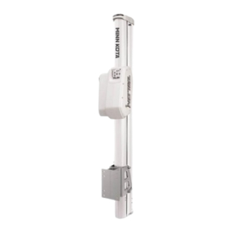
- Page 1 12'/ 10' INSTALLATION MANUAL minnkotamotors.com | 1 ©2013 Johnson Outdoors Marine Electronics, Inc.
-
Page 2: Getting Started
GETTING STARTED PARTS INCLUDED Your new 12' or 10' Talon comes out of the box with everything you’ll need for direct-to-transom mounting. If you have an irregular shaped transom that cannot accept a direct-to-transom mount, please go to minnkotamotors.com for details on our universal mounting brackets, and to locate your closest dealer. -
Page 3: Mounting Options
1. Direct Transom Mount (recommended) 2. Optional Adapter Plate. If you’re not mounting Talon directly to the transom, you’ll need one of our adapter plates to offset the unit from the back of the boat. For more information on adapter plate applications and purchasing, visit minnkotamotors.com. - Page 4 (Figure 1). NOTE: The Talon mounting bracket can be mounted directly to the transom (recommended) or to an adapter plate when direct transom mounting is not possible due to obstructions or irregular-shaped transoms.
- Page 5 ENGINE REVIEW When selecting a mounting location make sure that no interference exists between the Talon and your engine during normal operation. Once you have selected your mounting location, trim the engine all the way up and all the way down, and steer the engine fully to the side selected. Ensure there is two to three inches of clearance from any point on the Talon.
- Page 6 REAR REVERSE-TRANSOM ANGLE REVIEW Figure 6. Some boats may be manufactured with a “reverse-transom angle.” In these cases, the Talon mounting bracket may be mounted upside-down as shown to compensate for the reverse angle (Figure 6). 6 | minnkotamotors.com ©2013 Johnson Outdoors Marine Electronics, Inc.
- Page 7 INSTALLING THE TALON STEP 2 MOUNTING BRACKET If you have followed Step 1 carefully and you are Figure 7. installing the mounting bracket directly to the transom, you are now ready to drill holes. Please make one final check to ensure that you have met...
- Page 8 You can now adjust the angle of the mounting straps to achieve proper orientation Figure 11. based on the angle of your transom. 2. To install the Talon assembly onto the mounting Align Talon with bracket, the Talon assembly has two (2) vertical Stop...
- Page 9 STEP 3 — ATTACHING THE TALON TO THE MOUNTING BRACKET 5. Adjust the angular pitch of the Talon so the anchor Figure 13. is perpendicular with the horizon by removing the bottom two (2) mounting bolts from the bracket, adjusting the angle and then replacing the bottom two (2) mounting bolts in the appropriate angled hole (Figure 13).
- Page 10 18AWG. Cut off the sealed end of the green wire and splice the green wire to the user installed wire. Make sure to NOTE: The Talon does draw a small amount of residual current from the battery even when not in use. If the boat will not be used for more than 30 days, the power leads should be disconnected from the battery.
- Page 11 OPTIONAL DEPLOYMENT ALARM MINIMUM 18 AWG WIRE IGNITION SWITCH PROPER CONNECTION OF THE GREEN WIRE IS REQUIRED FOR YOUR WARRANTY, AND IS CRITICAL FOR THE SAFETY OF YOUR BOAT AND THE TALON. minnkotamotors.com | 11 ©2013 Johnson Outdoors Marine Electronics, Inc.
- Page 12 NOTE: If you adjust the angle of your Talon after step is complete, you will need to readjust the placement of the water deflection shield to ensure proper functionality.
-
Page 13: Verifying Installation
(for this test your Talon must be able to deploy and Deployment Indicator Lights make contact with the ground without hitting any Mode Button obstructions). 2. On the front control panel of the Talon are three (3) Rough Water Mode Indicator switches: Auto UP switch , Auto DOWN switch Light and MODE toggle switch . -
Page 14: Frequently Asked Questions
A. Some boats have irregular-shaped transoms and the standard Talon quick release mounting bracket cannot be mounted directly to the transom. In other cases there are other accessories such as trim tabs, transducers, poling platforms, etc., that may require additional clearance. Use the Talon Adapter Bracket Selection Guide to select the proper application for your boat. - Page 15 NOTES minnkotamotors.com | 15 ©2013 Johnson Outdoors Marine Electronics, Inc.
- Page 16 SHALLOW WATER ANCHOR MINN KOTA CONSUMER 121 Power Drive & TECHNICAL SERVICE. Mankato, MN 56001 P.O. Box 8129 Phone (800) 227-6433 Mankato, MN 56002 Fax (800) 527-4464 16 | minnkotamotors.com 2377159 RevB ECN 35487 03/14 ©2013 Johnson Outdoors Marine Electronics, Inc.
Need help?
Do you have a question about the Talon and is the answer not in the manual?
Questions and answers