Table of Contents
Advertisement
Advertisement
Table of Contents
Troubleshooting

Related Manuals for PolyScience Chiller


Summary of Contents for PolyScience Chiller
- Page 1 Operator’s Manual Refrigerated Recirculating Chillers 110-240 06.13.11...
-
Page 2: Table Of Contents
Table of Contents Introduction................................3 General Information..............................4 General Safety Information ............................ 4 Safety Recommendations............................4 Unpacking Your Chiller ............................5 Regulatory and Compliance Testing........................5 Contents................................. 5 Controls and Components ............................. 6 Quick Start................................7 Installation and Startup............................8 Site Requirements .............................. - Page 3 Fluid Filter................................. 24 Fluid Level ................................ 24 Temperature Calibration........................... 24 Troubleshooting ..............................25 Diagnostic Mode ..............................26 Technical Information ............................27 General Specifications (all Chillers) ........................27 Pump Performance .............................. 27 Performance Specifications – 60Hz Chillers......................28 1/4-HP, 1/3-HP and 1/2-HP Chillers......................... 28 3/4-HP and 1-HP Chillers ..........................
-
Page 4: Introduction
Centrifugal, positive displacement, or regenerative turbine pump • It will take you very little time to get your Recirculating Chiller installed and running. This manual is designed to guide you quickly through the process. We recommend that you read it thoroughly before you begin. -
Page 5: General Information
When installed, operated, and maintained according to the directions in this manual and common safety procedures, your Chiller should provide safe and reliable heat removal. Please ensure that all individuals involved in the installation, operation, or maintenance of this unit read this manual thoroughly prior to working with the unit. -
Page 6: Unpacking Your Chiller
Unpacking Your Chiller Your Chiller is shipped in a special carton. Retain the carton and all packing materials until the unit is completely assembled and working properly. Set up and run the unit immediately to confirm proper operation. Beyond one week, your unit may be warranty repaired, but not replaced. -
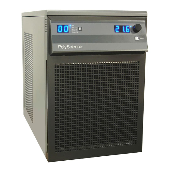
Page 7: Controls And Components
Controls and Components Reservoir Cap and Fluid Filter Port (top rear) Temperature Display Pressure / Flow Rate Display Select/Set Knob Pressure / Flow Rate Units Power Button Units / Menu Select Button Ambient Tracking / Remote Temperature Probe Connection (optional) Air Filter Reservoir Fluid Level Gauge... -
Page 8: Quick Start
Quick Start See Installation & Startup for additional information. Connect all process lines Fill reservoir with coolant Connect electrical power cord to Mains Turn Power Switch / Circuit Breaker ON Turn Controller ON Add coolant to reservoir as process lines fill Enter temperature set point 110-240... -
Page 9: Installation And Startup
Adequate clearance should be allowed on the front, sides, and rear of the Chiller for access to connections and components. The front and rear vents of the Chiller must be a minimum of 24 inches (61 cm) away from walls or vertical surfaces so air flow is not restricted. -
Page 10: Optional Signal Inputs/Outputs
Remote I/O Port This option allows you to use an external 12 VDC signal or a dry contact closure to turn the Chiller on and off. Chiller status is also available from this port. A 15-pin D-connector is provided on the rear of the instrument enclosure for this connection. -
Page 11: Closed Sytem Or Cooling Coil Setup
Fill the external bath (see Startup, Process Coolant for suitable fluids). Fill the Chiller reservoir to the top of the filler neck and install the filter screen and cap. Tighten the cap until it is securely sealed. -
Page 12: Electrical Power
A. Set the flow alarm to at least 4 LPM (see “Minimum Flow Rate”) B. Open the inlet and outlet valves on the Chiller; the suction created by the pump should begin drawing fluid through the inlet tubing into the Chiller reservoir. - Page 13 Chiller reservoir should be checked periodically to avoid low fluid conditions. To check the reservoir fluid level, close the inlet and outlet valves, turn the Chiller ‘off’, and remove the reservoir cap. Slowly open the inlet and outlet valves and allow fluid to drain from the external reservoir into the Chiller reservoir.
-
Page 14: Normal Operation
Displaying and Adjusting the Ambient Tracking Offset NOTE: Ambient tracking is an optional function that may or may not be available on your Chiller. It permits you to control fluid temperature based on room or machine temperature plus or minus a user-adjustable offset temperature. -
Page 15: Displaying And Adjusting The Remote Control Temperature
Selecting the Pressure / Flow Rate Display and Units The Chiller can be set up to display either fluid pressure (in PSI or kPa) or if fitted with flow sensor flow rate in GPM (Option E) or lpm (Option M). Pressing the Units/Menu Select button briefly toggles through the available selections. -
Page 16: Setting Operational Parameters
Setting Operational Parameters The Chiller’s various operational parameters, such as temperature, flow rate, and pressure alarm values, are all user-adjustable. They are accessed by pressing and holding the Units/Menu Button until HL appears on the pressure/flow rate display. Pressing and releasing the Units/Menu Button once HL appears allows you to scroll through the various parameters;... -
Page 17: High Temperature Limit (Hl)
NOTE: This value is always set in °C. This menu item protects the Chiller from overheating due to a high ambient temperature. Should the ambient temperature rise above the limit value, the audio and visual alarms will activate, and the compressor, heater, fan, and pump will turn off. -
Page 18: Minimum Flow Rate (Fl)
With FL set to “0”, the flow alarm is disabled, and the chiller will continue to operate with the output flow blocked. NOTE: When FL first appears, the Option E LED will be lit, indicating the FL value is GPM. To view the FL value in LPM, press the Units/Menu Button again. -
Page 19: Auto-Refrigeration Temperature (Af)
The rate of cooling is controlled through the maximum differential temperature setting (Sd) (see “Maximum External / Internal Temperature Differential”). If you do not wish to operate the Chiller using either of these external probes, rotate the Select/Set knob until NO is displayed. -
Page 20: Internal Calibration Offset (C1)
This menu item allows you to adjust the Chiller’s internal temperature reading to match that of a traceable standard. It allows you to offset the displayed temperature value by as much as ±2.9°C. -
Page 21: Baud Rate (Pc)
If this lasts for more than 5 seconds, Fault 17 occurs. (select models only) Lower ambient temperature. External remote control active, Chiller in standby Normal — Unit idle until remotely activated. (for units with remote control by 12 VDC option) External remote control active, Chiller in standby Normal —... - Page 22 To clear the fault, turn the unit off then on using the panel power button, and increase the HL value. Alarm — Process fluid temperature is above Chiller’s factory set high temperature safety cutoff. Heater, compressor, and fan turned off;...
- Page 23 Fault Code Description Action Required Alarm — Fluid temperature has exceeded 82°C (180°F) for more High bath temperature than 5 seconds. Compressor, heater, fan, and pump are turned off. alarm Lower fluid temperature. Alarm — Flow rate has dropped below minimum flow rate setting for more than 10 seconds.
-
Page 24: Adjusting The High Pressure Bypass Setting
To access the high-pressure bypass valve, remove the two screws at the upper left and right corners of the Chiller’s rear panel, slide the top panel back about 2-3 inches, and lift off. The regulator valve is located in the left rear corner of the unit. -
Page 25: Routine Maintenance And Troubleshooting
Fluid Level The fluid level gauge on the rear of the Chiller should be periodically checked to determine if the fluid level needs to be topped off. Generally, fluid should be added whenever the level in the reservoir is at or near the “Low”... -
Page 26: Troubleshooting
Blocked air ventilation screens Remove blockages as required. Excessive heat load Check that heat load does not exceed capacity of chiller; correct as required. Ambient air temperature too Decrease ambient air temperature. high Low or high line voltage Check and correct as required. -
Page 27: Diagnostic Mode
Diagnostic Mode NOTE: The Chiller must be set up to display temperature in °C in order to access the diagnostic mode. The Chiller incorporates a Diagnostic mode, which displays important operational information that can aid in troubleshooting. To access the Diagnostic mode, place the Circuit Breaker/Power Switch in the “Off” position and then return it to the “On”... -
Page 28: Technical Information
Technical Information General Specifications (all Chillers) Temperature Set Point Resolution ±0.1°C Temperature Stability ±0.1°C Temperature Units °C or °F Pressure Units PSI or kPa Pressure Display Resolution 1 PSI / 6.9 kPa Pressure Display Accuracy ±3.5% of full scale (100PSI) Flow Rate Units GPM or LPM Flow Rate Display Resolution... -
Page 29: Performance Specifications - 60Hz Chillers
Performance Specifications — 60Hz Chillers 1/4-HP, 1/3-HP and 1/2-HP Chillers Magnetic Drive Centrifugal Pump (60Hz) Model: Rfg = Refrigerating Only Rfg / Htg = Refrigerating & Heating Model Type Rfg / Htg Rfg / Htg Rfg / Htg -10° to -10°... - Page 30 Positive Displacement Pump (60Hz) Model: Rfg = Refrigerating Only Rfg / Htg = Refrigerating & Heating Model Type Rfg / Htg Rfg P Rfg / Htg Rfg / Htg -10° to -10°C to -10° to -10°C to -10° to -10° to Operating Temperature 40°C 70°C...
-
Page 31: 3/4-Hp And 1-Hp Chillers
3/4-HP and 1-HP Chillers Magnetic Drive Centrifugal Pump (60Hz) Model: Rfg = Refrigerating Only Rfg / Htg = Refrigerating & Heating Model Type Rfg / Htg Rfg / Htg Operating Temperature -10° to 40°C -10° to 70°C -10° to 40°C -10 to 70°C Compressor 3/4 HP... - Page 32 12.5A Specifications subject to change without notice. Refer to the serial number plate on the rear of the Chiller for model and electrical data. Notes: Cooling capacity (watts x 3.41) = BTU/hour. Performance specifications determined at ambient temperature of 20°C (68°F).
-
Page 33: Performance Specifications - 50Hz Chillers
Performance Specifications — 50Hz Chillers 1/4-HP, 1/3-HP and 1/2-HP Chillers Magnetic Drive Centrifugal Pump (50Hz) Model: Rfg = Refrigerating Only Rfg / Htg = Refrigerating & Heating Model Type Rfg / Htg Rfg / Htg Rfg / Htg -10° to -10°... - Page 34 Positive Displacement Pump (50Hz) Model: Rfg = Refrigerating Only Rfg / Htg = Refrigerating & Heating Model Type Rfg / Htg Rfg P Rfg / Htg Rfg / Htg -10° to -10°C to -10° to -10°C to -10° to -10° to Operating Temperature 40°C 70°C...
-
Page 35: 3/4-Hp And 1-Hp Chillers
3/4-HP and 1-HP Chillers Magnetic Drive Centrifugal Pump (50Hz) Model: Rfg = Refrigerating Only Rfg / Htg = Refrigerating & Heating Model Type Rfg / Htg Rfg / Htg Operating Temperature -10° to 40°C -10° to 70°C -10° to 40°C -10 to 70°C Compressor 3/4 HP... - Page 36 12.5A Specifications subject to change without notice. Refer to the serial number plate on the rear of the Chiller for model and electrical data. Notes: Cooling capacity (watts x 3.41) = BTU/hour. Performance specifications determined at ambient temperature of 20°C (68°F).
-
Page 37: Diagrams And Schematics
Diagrams and Schematics Electrical Wiring Diagram 110-240... -
Page 38: Flow Schematic
Flow Schematic 110-240... -
Page 39: Replacement Parts
Replacement Parts All 1/4-HP Units 120V, 60Hz 240V, 50Hz Condensing unit, ¼ HP 750-157 750-158 Magnetic Drive Pump (models without heat) 525-551 525-552 Magnetic Drive Pump (models with heat) 525-553 525-554 Positive Displacement Motor (all models) 215-535 215-529 Positive Displacement Pump (all models) 215-105 215-105 Turbine Pump (all models) - Page 40 All 3/4-HP Units 208-230V, 60Hz 240V, 50Hz Condensing unit, ¾ HP 750-304 750-303 Magnetic Drive Pump (models without heat) 525-552 525-552 Magnetic Drive Pump (models with heat) 525-554 525-554 Positive Displacement Motor (all models) 215-217 215-217 Positive Displacement Pump (all models) 215-106 215-106 Turbine Pump (all models)
-
Page 41: Rs232 Communications
RS232 Communications Serial Connector — A 9-pin D-connector is provided on the back panel of the Chiller for RS232 data communication. A serial cable that uses only the following pins should be used to connect the Chiller to the computer: Pin #2 —... -
Page 42: Equipment Disposal (Weee Directive)
Service and Technical Support If you have followed the troubleshooting steps and your Recirculating Chiller fails to operate properly, contact the supplier from whom the unit was purchased. Have the following information available for the customer service... -
Page 43: Warranty
(B) the exclusion or limitation of incidental or consequential damages, so the above limitations or exclusions may not apply to you. This warranty gives you specific legal rights. You may have other rights that vary from state to state. Manufactured by: PolyScience 6600 W. Touhy Avenue Niles, IL 60714 U.S.A. 1-800-229-7569 ● 1-847-647-0611 www.polyscience.com...
Need help?
Do you have a question about the Chiller and is the answer not in the manual?
Questions and answers