Table of Contents
Advertisement
Advertisement
Table of Contents

Related Manuals for PolyScience Refrigerated Recirculating Chillers


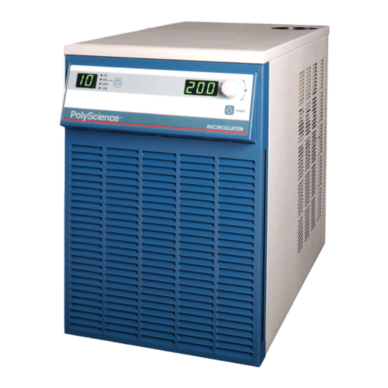
Summary of Contents for PolyScience Refrigerated Recirculating Chillers
- Page 1 Operators Manual Refrigerated Recirculating Chillers 110-240 Rev. H 06/06...
-
Page 2: Ec Declaration Of Conformity
The Products herewith complies with the requirements, as stated below, in accordance to the EC Low Voltage Directive 73/23/EEC and EC Electromagnetic Compatibility Directive 89/336/EEC, and carries the marking accordingly. We herewith declare: PolyScience Division of Preston Industries, Inc. 6600 West Touhy Avenue P.O. Box 48312 Niles, Illinois 60714, USA That the following equipment complies with the essential requirements in respect to safety and health, in accordance to the EC Directives based on its design and type, as brought into circulation by us. - Page 3 Requirements for waste collection, reuse, recycling, and recovery programs vary by regulatory authority at your location. Contact your local responsible body (e.g., your laboratory manager) or authorized representative for information regarding applicable disposal regulations. Contact PolyScience at the web site listed below for information. Web address: www.polyscience.com Customer Care: 1-800-229-7569...
-
Page 4: Table Of Contents
Table of Contents Section 1 - General Information Warranty Unpacking Section 2 – Overview Contents Description Chiller Specifications and Pump Performance Section 3 – Installation and Startup Site Requirements Electrical Power Optional Signal Inputs/Outputs Plumbing Closed System or Cooling Coil Setup Open Bath System Setup Startup Section 4 –... -
Page 5: Section 1 - General Information
Section 1 - General Information Warranty Thank you for purchasing this chiller. We are confident it will serve you for a long time. Our warranty to you is as follows: The manufacturer agrees to correct for the original user of this product, either by repair, or at the manufacturer's election, by replacement, any defect that develops after delivery of this product within the period as stated on the warranty card. -
Page 6: Section 2 - Overview
As a result, temperature stability is greatly enhanced and compressor life extended. Refrigerated Recirculating Chillers are equipped with either a centrifugal, positive displacement, or regenerative turbine pump. Wetted parts within the recirculation system are brass, stainless steel, polyethylene, EPDM rubber, and nylon. -
Page 7: Chiller Specifications And Pump Performance
Chiller Specifications and Pump Performance General Specifications (all Chillers) Temperature Set Point Resolution ±0.1° C Temperature Stability ±0.1° C Temperature Units ° C or ° F Pressure Units PSI or kPa Pressure Display Resolution 1 PSI / 6.9 kPa Pressure Display Accuracy ±3.5% of full scale (100PSI) Flow Rate Units GPM or LPM... - Page 8 Specifications — 1/4-HP, 1/3-HP, and 1/2-HP Chillers Model: Rfg = Refrigerating Only Rfg / Htg = Refrigerating & Heating Magnetic Drive Centrifugal Pump Model Rfg / Htg Rfg / Htg -10° to -10° to -10° to -10° to Operating Temperature -10°...
- Page 9 Model: Rfg = Refrigerating Only Rfg / Htg = Refrigerating & Heating Turbine Pump (“T” Series Chillers) Model T Series Chillers Rfg / Htg Rfg / Htg -10° to -10° C to -10° to -10° C to Operating Temperature -10° to 40° C 40°...
- Page 10 Specifications — 3/4-HP and 1-HP Chillers Model: Rfg = Refrigerating Only Rfg / Htg = Refrigerating & Heating Magnetic Drive Centrifugal Pump Model Rfg / Htg Rfg / Htg Operating Temperature -10° to 40° C -10° to 70° C -10° to 40° C -10 to 70°...
- Page 11 Model: Rfg = Refrigerating Only Rfg / Htg = Refrigerating & Heating Turbine Pump (“T” Series Chillers) Model T Series Chillers Rfg / Htg Rfg / Htg Operating Temperature -10° to 40° C -10° to 70° C -10° to 40° C -10°...
-
Page 12: Section 3 - Installation And Startup
Section 3 – Installation and Startup WARNING: Be sure all power is off before proceeding. Site Requirements Ambient Temperature and Relative Humidity The Chiller is designed for indoor installation in ambient temperatures between 5° and 30° C (41° and 86° F); relative humidity should not exceed 80% (non-condensing). Location The Chiller should be installed on a strong, level surface. -
Page 13: Plumbing
Remote I/O Port This option allows you to use an external 12 VDC signal to turn the Chiller on and off. A 9-pin D- connector is provided on the rear of the instrument enclosure for this connection. Plumbing Process Piping The Chiller has two internally threaded (1/2 inch ID NPT) fittings on the rear of the instrument housing for the process water connections. -
Page 14: Startup
Startup Process Coolant Suitable Fluids IMPORTANT: Only use fluids that will satisfy safety, health, and equipment compatibility requirements. Caustic, corrosive, or flammable fluids must never be used. The Chiller is designed to accommodate a variety of coolant fluids (water, glycol mixtures, etc). For most applications above 20°... -
Page 15: Section 4 - Operation
Section 4 Section 4 Section 4 Section 4 – – – – Operation Operation Operation Operation NOTE: The Chiller incorporates a special “lockout” feature that can be enabled to prevent unauthorized or accidental changes to set point and other operational values. This feature is described in detail in Section 4.8. -
Page 16: Selecting Internal/External Temperature Display
Note: The flow readout is intended as a reference only. If accurate flow readings are required an external flow meter is recommended. NOTE: Metric pressure reading output must be multiplied by 100 for kPa. Selecting the Internal/External Temperature Display NOTE: This section applies only when the ambient tracking probe or remote temperature control are installed and enabled. -
Page 17: Setting Operational Parameters
Setting Operational Parameters The Chiller’s various operational parameters, such as temperature, flow rate, and pressure alarm values, are all user-adjustable. They are accessed by pressing and holding the Units/Menu Button until HL appears on the pressure/flow rate display. Pressing and releasing the Units/Menu Button once HL appears allows you to scroll through the various parameters;... - Page 18 4.7.1 High Temperature Limit (HL) This menu item serves two functions. First, it establishes the maximum allowable set point temperature and thus helps prevent an operator from inadvertently setting the temperature set point above a pre-established temperature. Secondly, it serves as a high temperature alarm, automatically activating both audio and visual alarm indicators when the measured fluid temperature reaches the HL setting.
- Page 19 pressure value is set at the factory, but is user-adjustable. See Section 4.9 for information on changing the maximum outlet pressure value. 4.7.5 Minimum Flow Rate (FL) This is the minimum allowable flow rate and can be set in either GPM or LPM (the LED adjacent to the display indicates the active unit of measure).
- Page 20 temperature sensed by the ambient tracking probe (this may be room or machine temperature) plus or minus a user-set offset temperature (see Section 4.3). If you wish to operate the Chiller using the remote temperature probe, rotate the Select/Set Knob until rPC is displayed.
- Page 21 Rotate the Select/Set Knob until the desired calibration offset is displayed. Press the Select/Set Knob or simply allow the display to time out to accept the displayed value. 4.7.11 Flow Rate Calibration (F This menu item allows you to adjust the Chiller’s displayed flow rate reading to match that of a traceable standard.
-
Page 22: Display, Alarm, And Error Messages
Display, Alarm, and Error Messages When certain conditions are detected, a message code flashes on the display and the local audio alarm sounds. Depending on the nature of the condition, power to various systems components, such as the compressor, heater, fan, and pump, is removed. When condition is rectified, push front panel Power button or turn circuit breaker off then on to clear the fault or error. - Page 23 Message Description Action Required Code Factory Reserved None. Alarm — Process fluid temperature has dropped to low temperature limit value. Compressor, heater, fan, and pump turned off. Low limit temperature alarm Increase heat load on Chiller or decrease low temperature limit value. Alarm —...
- Page 24 Message Description Action Required Code Fault — Internal electronics failure. Power to Communications fault compressor, heater, fan, and pump turned off. Contact supplier. Fault — ADC for internal probe faulty. Power to compressor, heater, fan, and pump turned off. ADC fault, internal probe Contact supplier.
-
Page 25: Adjusting The High Pressure Bypass Setting
Adjusting the High Pressure Bypass Setting The Chiller incorporates an automatic safety to maintain outlet pressure below a valve-regulated pressure. This valve is adjustable and is located inside the Chiller housing. CAUTION: There are exposed fan blades inside the Chiller housing. Exercise extreme care when accessing or adjusting any interior components. -
Page 26: Section 5 - Maintenance And Calibration
Section 5 - Maintenance and Calibration The Chiller is designed to require a minimum of periodic maintenance. Standard Magnetic Drive Centrifugal Pump When used under continuous operating conditions, this pump should be oiled every six (6) months with SAE 20 oil. The pump incorporates two oil ports for this purpose. To access the pump: Turn both power switches off and unplug the power cord. -
Page 27: Section 6 - Troubleshooting
Section 6 – Troubleshooting WARNING: Refer servicing to qualified service personnel. When power is on, dangerous voltages exist within chassis components. Use extreme care when measuring voltages on live circuits. Unit Will Not Operate (no cooling or pumping) • Check that the power cord is plugged in to an operating electrical outlet. •... -
Page 28: Diagnostic Mode
Diagnostic Mode NOTE: The Chiller must be set up to display temperature in ° C in order to access the diagnostic mode. The Chiller incorporates a Diagnostic mode, which displays important operational information that can aid in troubleshooting. To access the Diagnostic mode, place the Circuit Breaker/Power Switch in the “Off”... -
Page 29: Electrical Wiring Diagram
Electrical Wiring Diagram... - Page 30 Flow Diagram...
-
Page 31: Section 8 - Replacement Parts
Section 8 - Replacement Parts ALL 1/4 HP UNITS 120V, 60Hz 240V, 50Hz ALL 1/3 HP UNITS 120V, 60HZ 240V, 50HZ Part Description Part No. Part No. Part Description Part No. Part No. Condensing Unit, ¼ hp 750-157 750-158 Condensing Unit, ⅓ hp 750-306 750-189 Magnetic Drive Pump... -
Page 32: Section 9 - Rs232
Section 9 - RS232 Serial Connector — A 9-pin D-connector is provided on the back panel of the Chiller for RS232 data communication. A serial cable that uses only the following pins should be used to connect the Chiller to the computer: Pin #2 —...
Need help?
Do you have a question about the Refrigerated Recirculating Chillers and is the answer not in the manual?
Questions and answers