Advertisement
Quick Links
Download this manual
See also:
Instruction Manual
SERVICE MANUAL
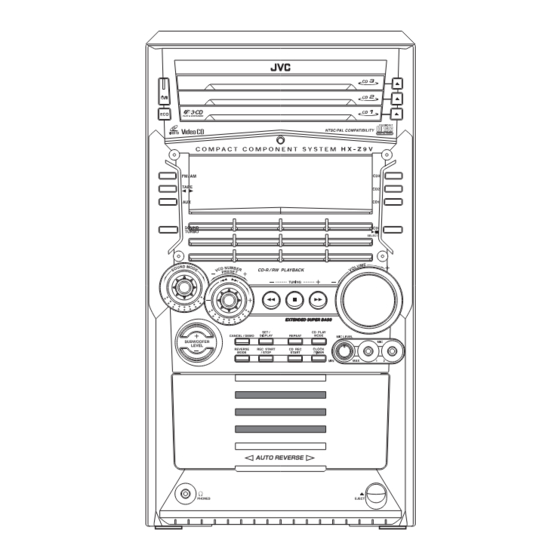
COMPACT COMPONENT SYSTEM
6
2003
22041
1
Precautions . . . . . . . . . . . . . . . . . . . . . . . . . . . . . . . . . . . . . . . . . . . . . . . . . . . . . . . . . . . . . . . . . . . . . . . . . . 1-3
2
Disassembly method . . . . . . . . . . . . . . . . . . . . . . . . . . . . . . . . . . . . . . . . . . . . . . . . . . . . . . . . . . . . . . . . . . 1-5
3
Adjustment. . . . . . . . . . . . . . . . . . . . . . . . . . . . . . . . . . . . . . . . . . . . . . . . . . . . . . . . . . . . . . . . . . . . . . . . . . 1-34
4
Description of major ICs . . . . . . . . . . . . . . . . . . . . . . . . . . . . . . . . . . . . . . . . . . . . . . . . . . . . . . . . . . . . . . . 1-40
COPYRIGHT © 2003 VICTOR COMPANY OF JAPAN, LIMITED
HX-Z9V
DIGITAL VIDEO
SELECT
CA-HXZ9V
TABLE OF CONTENTS
COMPACT
COMPACT
DIGITAL VIDEO
Area Suffix
US ------------ Singapore
No.22041
2003/5
Advertisement

Related Manuals for JVC HX-Z9V


Summary of Contents for JVC HX-Z9V
- Page 1 SERVICE MANUAL COMPACT COMPONENT SYSTEM 22041 2003 HX-Z9V COMPACT DIGITAL VIDEO SELECT COMPACT DIGITAL VIDEO CA-HXZ9V Area Suffix US ------------ Singapore TABLE OF CONTENTS Precautions ................1-3 Disassembly method .
- Page 2 SPECIFICATION Amplifier section Output Power (IEC 268-3) SUBWOOFERS 75 W per channel, min. RMS, both channels driven into 6 Ω at 63 Hz with no more than 0.9% total harmonic distortion. 30 W per channel, min. RMS, both channels driven into 6 Ω at 1 kHz MAIN SPEAKERS with no more than 0.9% total harmonic distortion.
-
Page 3: Precautions
SECTION 1 Precautions Safety Precautions (1) This design of this product contains special hardware and voltmeter. many circuits and components specially for safety purpos- Move the resistor connection to each exposed metal es. For continued protection, no changes should be made part, particularly any exposed metal part having a return to the original design unless authorized in writing by the path to the chassis, and measure the AC voltage across... - Page 4 Preventing static electricity Electrostatic discharge (ESD), which occurs when static electricity stored in the body, fabric, etc. is discharged, can destroy the laser diode in the traverse unit (optical pickup). Take care to prevent this when performing repairs. 1.5.1 Grounding to prevent damage by static electricity Static electricity in the work area can destroy the optical pickup (laser diode) in devices such as CD players.
-
Page 5: Disassembly Method
SECTION 2 Disassembly method Main body 2.1.1 Removing the metal cover (See Fig.1~3) Metal cover (1) Remove the six screws A on the back of the body. (2) Remove the screw B on each side of the body. (3) Remove the metal cover from the body by lifting the rear part of the cover. - Page 6 2.1.2 Removing the CD changer mechanism assembly CD changer (See Fig.4, 5) mechanism assembly • Prior to performing the following procedure, remove the metal cover. Front panel assembly (1) Disconnect the card wires from connector CN151 and CN651 on the CD servo control board on the right bottom of the CD changer mechanism assembly.
- Page 7 2.1.3 Removing the front panel assembly (See Fig.6~9) • Prior to performing the following procedure, remove the metal cover and the CD changer mechanism assembly. (1) Disconnect the card wires from connector CN44 and CN870, disconnect the flat wire from connector CN922 on the main board on the right side of the body.
- Page 8 2.1.4 Removing the antenna board Rear panel Antenna board (See Fig.10, 11) • Prior to performing the following procedure, remove the metal cover. (1) Disconnect the card wire from connector CN1 on the an- tenna board on the right side of the body. (2) Remove the band attaching the antenna board.
- Page 9 2.1.5 Removing the rear panel Rear panel (See Fig.12~16) • Prior to performing the following procedure, remove the metal cover and the CD changer mechanism assembly. (1) Remove holding board by remove two plastic rivets and then slide out the holding board as shown in fig.12. (2) Disconnect fan wire from connector CN206 on the bridge board.
- Page 10 2.1.6 Removing the T.flux board Front panel assembly (See Fig.17, 18) • Prior to performing the following procedure, remove the metal cover and the CD changer mechanism assembly . T.flux board (1) Disconnect the card wire from connector CN102 on the T.flux board.
- Page 11 2.1.7 Removing the fan assembly (See Fig.19, 20) • Prior to performing the following procedure, remove the metal cover, the CD changer mechanism assembly and the rear pan- (1) Remove two screws H on the rear panel. (2) Rotate fan assembly in clockwise direction to release fan assembly from rear panel (joints e).
- Page 12 2.1.9 Removing the bridge board / regulator board / heat sink (See Fig.22~27) Band • Prior to performing the following procedure, remove the metal cover, the CD changer mechanism assembly, the rear panel, the antenna board and main board. (1) Remove the plastic rivet attaching the stay inner bar and remove the screw I on the bridge board.
- Page 13 2.1.10 Removing the power transformer assembly Power transformer assembly (See Fig.28,29) • Prior to performing the following procedure, remove the metal cover, the CD changer mechanism assembly, the rear panel, the main board and the bridge board / regulator board. (1) Remove the screw O attaching the primary board.
- Page 14 Front panel assembly Head amplifier & mechanism control board • Prior to performing the following procedure, remove the metal CN33 cover, the CD changer mechanism assembly and front panel assembly. 2.2.1 Removing the cassette mechanism assembly (See Fig.30) (1) Disconnect the card wire from connector CN33 on the head amplifier &...
- Page 15 2.2.4 Removing the display system control board (See Fig.33, 34) Stay bracket (1) (1) Remove the four screws U attaching the stay bracket (1). (2) Disconnect the card wires from connector CN43 and CN880 on the display system control board. (3) Remove the ten screws V attaching the display system control board.
-
Page 16: See Fig.
2.2.5 Removing the button board (See Fig.35~39) • Prior to performing the following procedure, remove the dis- play system control board. (1) Pull out preset knob, sound mode knob on the front panel toward the front. (2) Pull out the volume knob and remove the two screws W at- taching the knob holder. -
Page 17: See Fig.
CD Changer Mechanism • Remove the CD changer mechanism assembly. 2.3.1 Removing the CD Servo control board (See Fig.1) (1) From bottom side the CD changer mechanism assem- bly,remove the four screws A retaining the CD servo con- trol board. (2) Absorb the four soldered positions a of the right and left motors with a soldering absorber. -
Page 18: No.22041)1
2.3.2 Removing the CD tray assembly T.Braket (See Fig.2~9) (1) Remove the CD servo control board. (2) Remove the screw B retaining the lod stopper. (3) From the T.bracket section b and clamper base section c , remove both of the edges fixing the rod. (4) Remove the three screws C retaining the T.bracket. - Page 19 Chassis assembly CD tray assembly Pawl Refer to Fig.7 Pulley gear Fig.6 Motor pulley Fig.8 CD tray assembly Drive unit of elevator Fig.7 Pawl Fig.9 2.3.3 Removing the CD loading mechanism assembly (See Fig.10) (1) While turning the cams R1 and R2 assembly in the arrow Cams R1, R2 assembly direction h ,align the shaft i of the CD loading mechanism assembly to the position shown in Fig.10.
- Page 20 2.3.4 Removing the CD traverse mechanism Cam R1, R2 assembly (See Fig.11 and 12) (1) For dismounting only the CD traverse mechanism without removing the CD loading mechanism assembly, align the shaft j of the CD loading mechanism assembly to the po- sition shown Fig.11 while turning the cam R1 and R2 as- Arrow sembly in the arrow direction k .
- Page 21 2.3.6 Removing the try select switch board Chassis assembly (See Fig.14) (1) Remove the two screws G retaining the tray select switch board. (2) Disconnect the tray select switch board from connector Tray select switch board CN854 on the CD servo control board. CN854 CN851 CD servo...
- Page 22 2.3.8 Removing the actuator motor and belt Chassis assembly (See Fig.18~21) (1) Remove the two screws I retaining the gear bracket. (2) While pressing the pawl t fixing the gear bracket in the ar- row direction, remove the gear bracket. (3) From the notch u section on the chassis assembly fixing Gear bracket the edge of gear bracket, remove and take out the gear...
- Page 23 2.3.9 Removing the cams R1/R2 assembly and cam gear q Slit washer (See Fig.22) (1) Remove the slit washer fixing the cams R1 and R2 assem- Cam R2 bly. Slit washer (2) By removing the two pawls w fixing the cam R1, separate Cam gear q R2 from R1.
- Page 24 2.3.11 Removing the Pickup unit Pickup unit Chassis base (See Fig.24 and 25) (1) Turn the cam gear in the direction of the arrow to move the Joint a pickup unit toward the center. (2) Extend the guide shaft stopper in the direction of the arrow, Pickup unit move the guide shaft and pull out as shown in the figure.
- Page 25 2.3.12 Removing the CD mechanism board (See Fig.26) (1) On the back of the CD mechanism assembly, unsolder the Soldering c four soldering c attaching the CD mechanism board, the spindle motor and the feed motor. (2) Removing the screw A. Spindle motor CD mechanism board Soldering c...
- Page 26 Cassette mechanism assembly 2.4.1 Removing the Play/Record & Clear head Cassette mechanism assembly Fly wheelR (See Fig.1~3) (1) While moving the trigger arm on the right side of the head mount in the direction of the arrow, turn the flywheel R counterclockwise until the head mount comes ahead and clicks.
- Page 27 2.4.2 Removing the head amplifier & mechanism control board (See Fig.4) (1) Turn over the cassette mechanism assembly and remove Main motor assembly the three screws A attaching the head amplifier & mecha- nism control board. Capstan belt (2) Disconnect the flexible wire from connector CN31 on the head amplifier &...
- Page 28 2.4.4 Removing the flywheel (See Fig.8, 9) • Prior to performing the following procedure, remove the head amplifier & mechanism control board and the main motor as- sembly. (1) From the front side of the cassette mechanism, remove the slit washers attaching the capstan shaft L and R. Pull out the flywheels backward.
- Page 29 2.4.6 Reattaching the Play/ Record & Clear head (See Fig.11~13) (1) Reattaching the head mount assembly. a) Change front of the direction cover of the head mount assembly to the left (Turn the head forward). b) Fit the bosses O', P', Q', U' and V' on the head mount assembly to the holes P and V, the slots O, U and Q of the mechanism sub assembly (See Fig.11 to 13).
- Page 30 Speaker section 2.5.1 Main speaker 2.5.1.1 Removing the front cover Joint a (See Fig.1, 2) CAUTION: Do not break or damage the front panel and body that are glued at the joints a. (See Fig.1) (1) Remove the four screws A on the front of the body respec- tively.
- Page 31 2.5.1.2 Removing the woofer speaker (See Fig.3) • Prior to performing the following procedure, remove the front cover. (1) Remove the four screws B on the front of the body. (2) Pull out the woofer speaker toward the front and discon- nect the wire (yellow and black, red and black) from the two speaker terminals.
- Page 32 2.5.2 Sub woofer 2.5.2.1 Removing the front cover (See Fig.5) Joint b Joint b CAUTION: Do not break or damage the front panel and body that are glued at the joints b. (See Fig.5) (1) Remove the front cover toward the front. Fig.5 2.5.2.2 Removing the sub woofer speaker...
- Page 33 2.5.3 Surround speaker Rear cover 2.5.3.1 Removing the rear cover (See Fig.7~9) (1) Remove the four screws F on the back of the body. (2) Disconnect the wires from the two terminals on the rear of the surround speaker. (3) Remove the four screws G on the back of the front cover. Fig.7 Front cover Rear cover...
-
Page 34: Adjustment
SECTION 3 Adjustment Measurement Instruments Required for Adjustment (1) Low frequency oscillator 3.2.2 Tuner section This oscillator should have a capacity to output 0dBs to Voltage applied to tuner +B : DC5.7V 600Ω at an oscillation frequency of 50Hz-20kHz. VT : DC 12V (2) Attenuator impedance : 600Ω... - Page 35 Cassette mechanism adjustment Head azinuth Head azinuth adjustment screw adjustment screw (Forward side) (Reverse side) CN31 Head azinuth Head azinuth R/P head, Erase head adjustment screw adjustment screw (Forward side) (Reverse side) Mecha control board VR37 R371 FW100 Motor speed CN33 VR37 C374...
- Page 36 Mechanism section Adjustment Item Condition Measurement method Ref. value position Head azimuth Test tape (1) Playback the test tape VT703L (8kHz). Maximum output Only adjust at :VT703L (8kHz) (2) Adjust to maximum output level by azimuth ad- changed head Output terminal justment screw for forward side and reverse :Speaker out side.
- Page 37 3.4.1 Electrical adjustment Adjustment Item Condition Measurement method Ref. value position Recording BIAS • Forward or Reverse (1) Set the test tape(AC-514 TYPE ll and AC-225 AC-225 VR31 adjustment • Test tape TYPE l), then make REC/PAUSE condition. : 4.20µA : AC-514 TYPE ll (2) Connect 100Ω...
- Page 38 Flow of functional operation untill TOC read (CD) Check Point Slider turns REST Power Key Power ON Check that the voltage at the pin 5 SW ON. of CN801 is 0V? Automatic tuning of TE offset Check that the voltage at the Laser ON pin2 of IC601 is 4.4V? Detection of disc...
- Page 39 Maintenance of laser pickup (CD) Replacement of laser pickup (CD) (1) Cleaning the pick up lens Before you replace the pick up, please try to clean the lens Turn off the power switch and, disconnect the with a alcohol soaked cotton swab. power cord from the ac outlet.
-
Page 40: Description Of Major Ics
SECTION 4 Description of major ICs 4.1 AN22000A-W (IC601) : RF head amp. • Terminal layout • Pin function Symbol I/O Function I APC Amp. input terminal O APC Amp. output terminal - Power supply terminal I RF adder Amp. inverting input terminal RFOUT O RF adder Amp. - Page 41 AN4801SB-W (IC801) : MD/CD driver • Pin Layout • Pin function Function Function Driver 2 input 15 Driver 3 forward output Power Cut input 16 Driver 4 inverted output (channel 2 mute) Driver 1 input 17 Driver 4 forward output Power Cut input 18 Power supply 2 for driver (channel 1 mute)
- Page 42 AT27C020-70JC6 (IC102) : OTP EPROM 2M bit • Pin Layout • Pin function Pin No. Function A0-A17 Addresses O0-O7 Outputs Chip Enable Output Enable Program Strobe • Block Diagram DATA OUTPUTS O0-O7 OUTPUT OE,CE AND BUFFERS PROGRAM LOGIC Y DECODER Y-GATING A0-A7 CELL MATRIX...
- Page 43 4.4 BU2092 (IC811) : Port expander • Terminal layout DATA CLOCK CONTROL CIRCUIT • Pin Function Pin No. Symbol Function Connect to GND DATE Serial Date input CLOCK Shift Clock of Date Latch Clock of Date 5~16 Q0~Q11 Parallel Date Output Latch Data OUTPUT ON OFF...
- Page 44 BH3874AKS2 (IC434) : Audio sound processor • Pin Layout • Block Diagram 63 64 3 4 7 8 11 12 -9dB FILTER INLD -30dB~- 0~30dB INLC 11dB INLB OUTL INLA 5 BAND EQ BASS5 19dB FILTER 5 BAND EQ 11dB INRA 10.5Hz OUTR...
- Page 45 • Pin function Pin No. Name Function Pin No. Name Function Serial data larch receiving pin F1R1 Rch GREQ f1 filter setting pin Serial clook receiving pin F1R2 Rch GREQ f1 filter setting pin Parallel data receiving pin F2L1 Lch GREQ f2 filter setting pin Parallel data receiving pin F2L2 Lch GREQ f2 filter setting pin...
- Page 46 4.6 BU9253AS (IC901) : LPF & Echo mix. • Pin layout & block diagram MUTE ECHO VR BIAS ADINT IN DAINT IN ADINT OUT DAINT OUT ADLPF OUT DALPF IN ADLPF IN DALPF OUT MIX IN MIX OUT • Pin function Symbol Description Pin No.
- Page 47 4.7 GLT44016-35J4-X (IC103) : Dram • Pin layout • Pin function Pin Name Function Address inpits Row address strobe UCAS Columu address strobe / upperbyte control LCAS Columu address strobe / lower byte control Write enable Output enable LCAS UCAS Dara inputs / outputs +5V power supply Ground...
- Page 48 ES3880F (IC104) : Video CD processor • Pin Layout • Block Diagram 32-Bit RISC Processor 8KB cache On-Screan Display Gateway and DMA Controller Transport Controller Interface Parser Huffman Decoder DRAM Serial Audio Interface Interface Video Processor • Pin function Pin No. Symbol Descriptions 2.85V power supply.
- Page 49 Pin No. Symbol Descriptions LWR# RISC interface write enable (active-low). LOE# RISC interface output enable (active-low). 65~67 LCS[3,1,0]# RISC interface chip select (active-low). 68~79 LA[0:17] RISC interface address. Ground. 5.0V power supply. 82~87 LA[0:17] RISC interface address. ACLK Master clock for external audio DAC (8.192MHz, 11.2896MHz, 12.288MHz, 16.9344MHz, and 18.432MHz).
- Page 50 ES3883F(IC104):VCD Companion chip • Pin function • Blockdiagram CD-ROM Controller Remote Interrupt Remote CD ROM Control Control receiver Audio DAC Speakers Vista ES3880 (Video CD) Television NTSC/PAL Video Echo/Surround/Vocal Assist Preamp Mic 1 Volume Control Preamp DRAM Mic 2 Volume Control Panel Driver •...
- Page 51 Pin No. Symbol Function TBCK Transmit audio bit clock. Dual-purpose pin RWS is the audio frame sync. SEL_PLL1 Pins SEL_PLL[1.0] select the PLL clock frequency for the DCLK output. SEL_PLL1 SEL_PLL0 DCLK Bypass PLL(input mode) 27 MHz(output mode) 32.4 MHz(output mode) 40.5 MHz(output mode) RSTOUT_B Reset output(active-low).
- Page 52 4.10 GP1UM271XK (IC901) : Dual operation amplifier Com- Demodu- Integra- para- Limiter B.P.F lator GND Vcc Vout 4.11 HA17758A (IC501,IC502,IC571) : Dual operational amp • Pin layout Vout1 Vin(-)1 Vout2 Vin(+)1 Vin(-)2 Vin(+)2 1-52 (No.22041)
- Page 53 4.12 KIA7805API (IC303, IC360) : Regulator • Pin layout 1.VCC 2.GND 3.OUTPUT • Block diagram INPUT Q11-1 OUTPUT COMMON (GND) (No.22041)1-53...
- Page 54 4.13 KIA7809API (IC305) : Regulator • Pin layout 1.INPUT 2.COMMON 3.OUTPUT 1 2 3 • Block diagram INPUT Q11-1 OUTPUT COMMON (GND) 1-54 (No.22041)
- Page 55 4.14 KIA7812API (IC240) : Regulator • Pin layout 1.VCC 2.GND 3.OUTPUT • Block diagram INPUT Q11-1 OUTPUT COMMON (GND) (No.22041)1-55...
- Page 56 4.15 LA1838 (IC1): FM AM IF AMP&detector, FM MPX Decoder • Block Diagram DECODER RF.AMP ANIT-BIRDIE MUTE BUFF STEREO P-DET AM IF PILOT 384KHz COMP S-METER AM/FM S-CLRVE S-METER IF-BUFF TUNING STEREO DRIVE DRIVE FM IF • Pin Function Pin No. Symbol Function FM IN...
- Page 57 4.16 LB1641 (IC851,IC852) : DC Motor driver • Pin layout • Truth table Input Output Mode OUT1 OUT2 Brake CLOCKWISE COUNTER-CLOCKWISE GND OUT1 P1 IN2 VCC1 VCC2 P2 OUT2 Brake 4.17 TC7W08FU-X (IC107) : Nand gate • Pin layout & Block diagram •...
- Page 58 4.18 LC72136N (IC2) : PLL frequency synthesizer • Pin layout FM/AM LPFOUT LPFIN CLOCK FM/ST/VCO FMIN AM/FM AMIN IFCONT SDIN IFIN • Block diagram Phase Reference Detector Driver Charge Pump Swallow Counter Swallow Counter 1/16,1/17 4bit 1/16,1/17 4bit Unlock Detector 12bit Programmable DriverS...
- Page 59 4.19 MN101C30AET1 (IC251) : CD micon • Pin Layout • Pin function Pin No. Symbol Function Pin No. Symbol Function CAM0 I/O LCAM control signal MX/UX I Connect to GND CAM1 I/O LCAM control signal - Connect to GND CAM2 I/O LCAM control signal VREF+ - Reference voltage...
- Page 60 4.20MN6627482WA (IC651) : DSP & DAC • Pin layout 20 ~ 41 ~ • Block diagram AVSS1 LRCKIN(MSEL) 8TIMES AVDD1 BCLK(SSEL) DIGITAL OVER SAMPUNC OUTR SRDATAIN DEEMPHSIS DIGITAL FILTER 1BIT (PSEL) LOGIC IOSEL CLVS BLKCK OUTL CLDCK SBCK SUBC DEMPH RESY FLAG6(RESY) FLAG...
- Page 61 • Pin function Pin No. Symbol Function Pin No. Symbol Function LDON Laser ON signal output (H:on) BCLK Not used PLLF2 Not used LRCK Not used TOFS Tracking error shunt signal output SRDATA Not used (H:shunt) DVDD1 Power supply (Digital) WVEL Not used DVSS1...
- Page 62 4.21 NJM4580L (IC902) : Dual Operational Amplifier 1. A OUTPUT • Terminal layout 2. A -INPUT 3. A +INPUT 4. V - 5. B +INPUT 6. B -INPUT 7. B OUTPUT 1 2 3 5 6 7 8 8. V 4.22 RT9161 / A-27CG-X (IC105) : Regulator •...
- Page 63 4.24 STK412-410 (IC701) : Power amp • Pin Layout • Block Diagram 18 17 TR41 Comparator TR12 TR11 TR16 TR19 R1 C1 TR18 TR14 TR20 TR10 TR13 TR15 TR17 Comparator TR51 9 8 11 10 4.25 TC7S08F-W (IC106) : Input nand gate •...
- Page 64 4.26 UPD784975AGF312 (IC810) : Main micon • Pin Layout • Pin function Pin No. Name Function Pin No. Name Function ECHO1 I/O Echo 1 data AVDD AD VDD, same as VDD1 ECHO2 I/O Echo 2 data SPIDTI SPI analog input SPI A I/O SPI A data Music scan input...
- Page 65 (No.22041)1-65...
- Page 66 VICTOR COMPANY OF JAPAN, LIMITED AV & MULTIMEDIA COMPANY AUDIO/VIDEO SYSTEMS CATEGORY 10-1,1chome,Ohwatari-machi,Maebashi-city,371-8543,Japan (No.22041) Printed in Japan...