
Related Manuals for Erbauer ERB052BTE


Summary of Contents for Erbauer ERB052BTE
- Page 1 WARRANTY YEARS ERB052BTE 8” THICKNESS PLANER BTP210F-M-070928.indd 1 2007-9-28 13:35:52...
- Page 2 Congratulations on your purchase of a quality power tool from Erbauer (UK) Ltd. This product should give you reliable service but for your peace of mind this power tool does carries a 24-month guarantee, the terms of which are detailed below.
-
Page 3: Safety Instructions
SAFETY INSTRUCTIONS Warning! When using electric tool, the following basic safety precautions should always be taken to reduce the risk of fire, electric shock and personal injury. Read all these instructions before attempting to operate the product and save these instructions for future reference. SAVE THESE INSTRUCTIONS 1. - Page 4 15. Disconnect tools. When not in use, before servicing and when changing accessories such as blades, bits and cutters, disconnect tools from the power supply. 16. Remove adjusting keys and wrenches. From the habit of checking to see that keys and adjusting wrenches are removed from the tool before turning it on.
-
Page 5: Specific Safety Instructions
HEALTH ADVICE Warning! When drilling, sanding, sawing or grinding, dust particles will be produced. In some instances, depending on the materials you are working with, this dust can be particularly harmful to you (e.g. lead from old gloss paint). You are advised to consider the risks associated with the materials you are working with and to reduce the risk of exposure.You should: - Work in a well-ventilated area. - Page 6 therefore wear ear protectors. 18. Any repairs to the planer thicknesser must be carried out only by a suitably qualified person. 19. Only original spare parts and accessories must be used, Otherwise the manufacturer does not offer any warranty and does not accept any liability for personal injury. 20.
- Page 7 19. Check the amount of cut on the blade before using the machine. 20. Never attempt a heavy cut in short stock. 21. Avoid cutting across the grain. 22. Use the push pads to keep your hands well away from the blades, particularly for shorter stick planing.
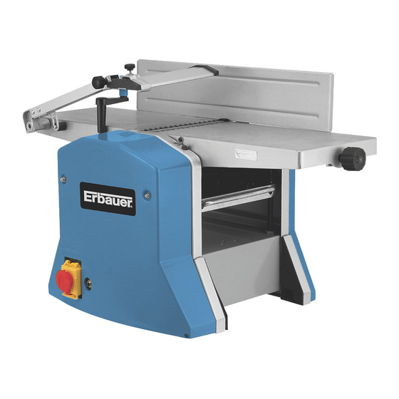
- Page 8 ON/OFF (NVR) SWITCH MOTOR OVERLOAD SWITCH RUBBER (ANTI VIBRATION) FEET THICKNESSER EXTENSION RAIL CUT DEPTH CONTROL KNOB (PLANER MODE) ADJUSTABLE (IN-FEED) TABLE (PLANER MODE) CHIP EXTRACTION OUTLET GUIDE FENCE BLADE (CUTTER) GUARD 10. BLADE GUARD LOCKING KNOB 11. HEIGHT ADJUSTING HANDLE (THICKNESSING MODE) 12.
-
Page 9: Technical Data
13. FIXED (OUT-FEED) TABLE (PLANER MODE) 14. BLADE GUARD ARM ASSEMBLY 15. SAFETY INTERLOCK SWITCH 16. 45° FENCE ANGLE STOP 17. ANGLE POINTER 18. 90° FENCE ANGLE STOP 19. ANGLE GUIDE 20. FENCE ANGLE LOCK HANDLE 21. CABLE CLIPS TECHNICAL DATA Volts: 230V~50Hz Power:... - Page 10 ACCESSORIES Crank Parallel guide 1set Dust collector Push block 2pcs Blade setting gauge Hex key 3pcs Spanner Subassembly stand cushion 1set Safety guard plate BTP210F-M-070928.indd 10 2007-9-28 13:35:54...
- Page 11 ASSEMBLY 1. Fitting the rubber (anti-vibration) feet (See Fig 1): 1) Carefully turn the machine upside down, taking care not to damage the in-feed / out-feed beds. 2) Fit the washers over the hex bolts and push both through the holes in the rubber feet. 3) Fit the feet / bolts to the holes provided (1 on each corner of the machine).
- Page 12 3. Fitting the blade (cutter) guard (9) (See Fig 5-9): 1) Familiarise yourself with the blade guard locating pivot pin (a), and the blade guard limiting screw pole (b) situated on the side of the planer out-feed table (13). 2) Remove the limiting screw. 3) Slide the guard arm assembly (14) over the locating pivot pin.
- Page 13 OPERATION Important: This planer-thicknesser is intended specifically planning thicknessing operations on solid timber.When being thickened, the contact surface of the work piece must be flat. If working with bigger or heavier work-pieces it is necessary to clamp the machine firmly to its supporting bench or table.
- Page 14 switch is in “off’ position. • After turning the switch on, allow the cutter block to come to full speed before commencing the operation. • Keep hands clear of all moving parts. • Do not force the cut. Slowing or stalling the cutter will force the overload to cut in and will greatly reduce the life of the motor.
- Page 15 3) Continue turning the handle until the thicknesser table reaches its lowest point. 4) On the bottom of the thicknesser table there are 3 holes, these are the locating holes for the corresponding locating points on the extraction port assembly. 5) Make note of “tab a”...
- Page 16 1.3 Setting the blade guard (9). (See Fig 18- 1) Loosen the blade guard locking knob (10). 2) Pull back the blade guard (9). 3) Set the workpiece against the guide fence (8). 4) Slide the blade guard (8) towards the workpiece (leaving a small gap of a few millimetres).
- Page 17 cutter-block). Caution: It is much safer (particularly when using a thin / small workpiece) to use the supplied push blocks. 7) Repeat these steps until the correct amount of material has been removed. Note: Keep firm and even pressure on the workpiece as it passes over the in-feed table and continue pushing forward until the back of the workpiece passes the cutter-block.
- Page 18 2.3 Thicknesser mode: Setting the depth of cut. (See Fig 27) The depth of cut is set by how high / low the thicknessing bed is in relation to the cutter-block. 1) Measure the workpiece. 2) Set the bed to just over this measurement, using the scale to the left of the in-feed table.
- Page 19 removed from the tool before turning it on. 2. During use. • Constantly check for abnormalities. Stop the operation immediately if something does not look or sound right and have the machine checked by a suitably qualified person. • Remove any buildup of chippings and pay particular attention around the base of the planer �...
- Page 20 � � � 6. Setting the positive stops on the guide fence:(See Fig 30-32) ������������� ������ The positive stops at 90° and 45° are set at the factory to ensure accuracy, however over time they may need to be reset. •...
- Page 21 � � � 7. Replacing the cutter blades: 1) Removing the blades. (See Fig 33-35) ������������� ������ Caution: Not to touch the tips of the blades as it would cause hurts to you. • Remove the guide fence (8). • Loosen the blade guard locking screw (10) and slide the blade guard (9) away from the cutter- block as far as it will go.
- Page 22 2) Fitting the blades: (See Fig 36-38) • Fit the blade correctly into the clamping device. • Slide both components into the cutter-block, taking care that they are fitted in the correct direction etc. • Centre the blade assembly laterally. •...
- Page 23 8. Replacing the motor brushes: (See Fig 39-41) Caution: This operation should only be carried out by a suitably qualified person. • Carefully turn the planer thicknesser onto its side. •This will expose the motor of the machine. • Take a slotted screwdriver (not supplied) and locate it in the slot on the motor brush cap.
-
Page 24: Troubleshooting
TROUBLESHOOTING Caution: Troubleshooting could lead to an increased risk to the operator due to the fact that safety guards / covers may have to be removed. It is therefore particularly important that all the measures necessary for safe working are taken. Fault Possible causes Possible solutions... - Page 25 The motor cuts out whilst Motor has exceeded Allow the motor to cool under load. its duty cycle and the and reset the overload. overload has cut in. Cutting depth is too great Allow the motor to cool so the overload has cut in. and reset the overload.
-
Page 26: Environmental Protection
ENVIRONMENTAL PROTECTION Waste electrical products should not be disposed of with household waste. Please recycle where facilities exist. For further information visit www.recycle-more.co.uk PLUG REPLACEMENT If you need to replace the fitted plug then follow the instructions below. Important The wires in the mains lead are coloured in accordance with the following code: Green &... -
Page 27: Declaration Of Conformity
Declaration of Conformity We, Importer Erbauer (UK) LTD BA22 8RT Declare that the product 8” THICKNESS PLANER ERB052BTE Complies with the essential health and safety requirements of the following directive: 2004/108/EC. –EMC Directive. 73/23 EEC, 93/68 EEC. –Low Voltage Directive. - Page 28 BTP210F-M-070928.indd 28 2007-9-28 13:36:06...
Need help?
Do you have a question about the ERB052BTE and is the answer not in the manual?
Questions and answers