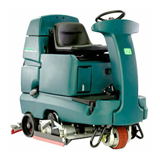
Nobles SPEED SCRUB RIDER Operator's Manual
Rider-scrubber
Hide thumbs
Also See for SPEED SCRUB RIDER:
- Specifications (2 pages) ,
- Brochure (3 pages) ,
- Operator's manual (54 pages)
Table of Contents
Troubleshooting

Related Manuals for Nobles SPEED SCRUB RIDER


Summary of Contents for Nobles SPEED SCRUB RIDER
- Page 1 SPEED SCRUB RIDER The Safe Scrubbing Alternativer RIDER- -SCRUBBER OPERATOR MANUAL Quick- Train Controls Hygenic Fully Cleanable Tanks 331140 Rev. 04 (02-2009) *331140* www.nobles.com Home Find... Go To..
- Page 2 PO Box 1452 Minneapolis, MN 55440 Phone: (800) 553--8033 or (763) 513--2850 www.nobles.com FaST- -PAK is a US registered and unregistered trademark of Tennant Company. Specifications and parts are subject to change without notice. Copyright E 2004- -2009 TENNANT Company, Printed in U.S.A.
-
Page 3: Table Of Contents
CONTENTS CONTENTS Page Page SAFETY PRECAUTIONS ....ON--BOARD BATTERY CHARGER OPERATION ......ERROR CODES . -
Page 4: Safety Precautions
SAFETY PRECAUTIONS SAFETY PRECAUTIONS The following symbols are used throughout this 3. When using machine: manual as indicated in the descriptions: - - Go slow on inclines and slippery surfaces. WARNING: To warn of hazards or - - Use care when backing machine. - - Report machine damage or faulty unsafe practices that could result in operation immediately. - Page 5 SAFETY PRECAUTIONS The safety labels appear on the machine in the locations indicated. If these or any label becomes damaged or illegible, install a new label in its place. BATTERY CHARGING LABEL - - FLAMMABLE SPILLS LOCATED ON THE SEAT PANEL LABEL - - LOCATED ON THE SEAT PANEL...
-
Page 6: Operation
OPERATION OPERATION MACHINE COMPONENTS A. Recovery tank drain hose M. Solution tank drain hose B. Recovery tank cover N. Squeegee hose C. Recovery tank O. Front solution tank cover D. Operator seat P. Hour meter E. Batteries Q. Circuit breakers F. -
Page 7: Controls And Instruments
OPERATION CONTROLS AND INSTRUMENTS ec- H2O Model A. Solution tank empty indicator B. Recovery tank full indicator C. Battery charge level indicators D. Fault indicator E. Emergency Stop Button F. Directional switch G. Horn button H. On/Off key switch I. One Step scrub button J. -
Page 8: How The Machine Works
OPERATION FOAM SCRUBBING SYSTEM (FaST MODEL) HOW THE MACHINE WORKS Unlike conventional scrubbing, the optional FaST (Foam Scrubbing Technology) system operates The scrub components of the machine are a by injecting the FaST--PAK concentrate agent into solution tank, scrub brushes or pads, a squeegee, the system with a small amount of water and air. -
Page 9: Ec--H2O Scrubbing (Ec--H2O Model)
OPERATION ec- H2O SCRUBBING (ec- H2O Model) BRUSH INFORMATION The ec- -H2O (electrically converted water) system operates by producing electrically converted water for cleaning. For best results, use the correct brush type for the cleaning application. The following are Normal water passes through a module where it is recommended brush applications. -
Page 10: Machine Setup
OPERATION MACHINE SETUP ATTACHING SQUEEGEE ASSEMBLY 1. Stop machine on a level surface. 2. Turn the machine ON/OFF key switch off. FOR SAFETY: Before leaving or servicing machine, stop on level surface, and turn off machine. 3. Place the rear squeegee under the squeegee mount bracket and fasten with the two knobs. -
Page 11: Filling The Solution Tank
OPERATION FILLING THE SOLUTION TANK MACHINE OPERATION The machine is equipped with a fill port at the rear of the machine. PRE- -OPERATION CHECKLIST - Check the battery fluid and charge level. - Check the tank cover seals for damage and wear. -
Page 12: Setting Scrub Modes
OPERATION SETTING SCRUB MODES SETTING BRUSH PRESSURE Before scrubbing, select the type of scrubbing will Under normal conditions, the brush pressure be used, FaST (option), ec- -H2O (option) or should be set to the minimum setting (the bottom conventional scrubbing. Then set the preferred light). -
Page 13: Economy Setting
OPERATION With the One Step Scrub button on, press either SCRUBBING Solution increase button (+) or Solution decrease FOR SAFETY: Do not operate machine, unless button (- -) to set the solution flow level for the operator manual is read and understood. surface being cleaned. - Page 14 OPERATION 6. Release the propel pedal to stop the machine. Scrubbing functions stop and the automatic park brake will engage when the machine stops. 7. The Brake pedal can be used to control the machine if quicker stopping is needed or if operating on an incline.
-
Page 15: Double Scrubbing
OPERATION DOUBLE SCRUBBING Place the side squeegees back on to the machine before scrubbing the floor the second time. For heavily soiled areas, use the double scrubbing method. NOTE: It is easier to put the side squeegees back on to the machine with the scrub head Double scrubbing can be performed using the partially lowered. -
Page 16: Water Pickup Mode (No Scrubbing)
OPERATION WATER PICKUP MODE (NO SCRUBBING) When scrubbing dead end aisles, start at the closed end of the aisle and scrub out towards the The machine can be used to pick up water or opening. non--flammable liquid spills without scrubbing. Adjust the machine speed, brush pressure, and To pick up water or non--flammable liquid spills, solution flow as required when scrubbing. -
Page 17: Emergency Stop Button
OPERATION EMERGENCY STOP BUTTON ec- H2O SCRUBBING: If an alarm sounds and the ec- -H2O system indicator light begins to blink The Emergency Stop Button halts all power to the red, the ec- -H2O module must be flushed to machine in case of an emergency. Press the resume ec- -H2O operation (See ec- -H2O button to halt the machine power. -
Page 18: Battery Discharge Indicator
OPERATION BATTERY DISCHARGE INDICATOR The battery discharge indicator shows the charge level of the batteries. When the batteries are fully charged, all five lights are lit. As the batteries discharge, the lights go out until only the left light is blinking. When the left light blinks, the scrubbing functions will shut off to alert the operator of the battery condition. -
Page 19: Fault Indicator
OPERATION FAULT INDICATOR The fault indicator light (shown in upper right) comes on when there a fault is detected in the propelling motor, vacuum fan motor, or brush motors. Refer to the table below to determine the cause for the fault or failure. Indicator(s) Cause(s) Remedy... -
Page 20: Circuit Breakers
OPERATION CIRCUIT BREAKERS FUSES Circuit breakers are resettable electrical circuit The fuse is a one-time protection device designed protection devices that stop the flow of current in to stop the flow of current in the event of a circuit the event of a circuit overload. Once a circuit overload. -
Page 21: Draining And Cleaning The Tanks
OPERATION NOTE: DO NOT use steam to clean tanks. DRAINING AND CLEANING THE TANKS Excessive heat can damage tanks and components. When cleaning is finished, or when the recovery tank full indicator comes on, the recovery tank should be drained and cleaned. The solution tank then can be filled again for additional cleaning. - Page 22 OPERATION 9. Close the recovery tank cover. 13. Carefully push the recovery tank forward to close the solution tank. 10.Remove the solution tank drain hose. While holding the hose up, remove the plug, then slowly lower the drain hose to the floor drain or sink.
-
Page 23: Propel System Troubleshooting
OPERATION 16. Cylindrical scrub head: Remove and clean the debris tray. Place the tray back in the scrub head when finished. 17. Replace the solution tank drain hose cap and mount the drain hose back onto the mounting clip after after the tank is drained. PROPEL SYSTEM TROUBLESHOOTING The audio alarm (horn) will sound and/or warning lights will come on when a propelling system fault... -
Page 24: Machine Troubleshooting
OPERATION MACHINE TROUBLESHOOTING Problem Cause Remedy Trailing water--poor or no Vacuum fan turned off Turn vacuum fan on water pickup Worn squeegee blades Rotate or replace squeegee blades Squeegee out of adjustment Adjust squeegee Vacuum hose clogged Flush vacuum hoses Vacuum fan filter dirty Clean vacuum fan filter Vacuum fan cover seals worn... - Page 25 OPERATION Problem Cause Remedy FaST System does not FaST switch is turned off Turn on the FaST switch operate Accessory circuit breaker tripped Reset circuit breaker Clogged FaST--PAK supply hose Soak connector and hose in warm and/or connector water and clean FaST--PAK carton is empty or not Replace FaST--PAK carton and/or connected...
-
Page 26: Maintenance
MAINTENANCE MAINTENANCE 355033 SpeedScrub Rider 331140 (02- -09) Home Find... Go To.. -
Page 27: Maintenance Chart
MAINTENANCE MAINTENANCE CHART No. of Lubricant/ Service Fluid Interval Description Procedure Points Check for damage and wear Daily Side and rear squeegees Check deflection and leveling Scrub brushes / pads Check for damage, wear, debris Recovery tank Clean tank, screen filter, and float sensor Vacuum fan filter Clean... -
Page 28: Batteries
MAINTENANCE BATTERIES LEAD ACID BATTERIES The batteries are designed to hold their power for Check the electrolyte level in each battery cell long periods of time. The lifetime of the batteries before and after charging, and after every 50 is limited to number of charges the batteries hours of operation. -
Page 29: Charging The Batteries With Off--Board Charger
MAINTENANCE NOTE: Do not take readings immediately after 4. Lead acid batteries: Check the water level in adding distilled water. If the water and acid are not all battery cells. If the level is low, add just thoroughly mixed, the readings may not be enough distilled water to cover the plates. -
Page 30: Checking On--Board Battery Charger Settings
MAINTENANCE 6. Plug the battery charger into the wall outlet. CHECKING ON- -BOARD BATTERY CHARGER SETTINGS NOTE: If the red “ABNORMAL CYCLE” lamp If your machine is equipped with the on--board lights when the TENNANT charger is plugged into charger, the charger settings must be set for your a wall outlet, the charger cannot charge the battery type before charging. -
Page 31: Charging The Batteries With The On--Board Charger
MAINTENANCE CHARGING THE BATTERIES WITH THE 5. The charger will display a sequence of codes ON- -BOARD CHARGER once the cord is connected. Three--digits + the following code: NOTE: If your machine is equipped with the A = Charging current on- -board battery charger, make sure that the U = Battery Voltage charger is properly set for your battery type before... -
Page 32: Electric Motors
MAINTENANCE ELECTRIC MOTORS BELTS (Cylindrical Models) The carbon brushes on the vacuum fan motor, the The two brush drive belts are located on the propelling motor, and the scrub brush motors cylindrical brush scrub head. The belts drive the should be inspected after the initial 500 hours of cylindrical brushes. -
Page 33: Scrub Brushes And Pads
MAINTENANCE REPLACING DISK BRUSHES OR PAD DRIVER SCRUB BRUSHES AND PADS 1. Stop machine on a level surface. Make sure the scrub head is in the raised position. The machine can be equipped with either disk or cylindrical scrub brushes, or cleaning pads. Check 2. -
Page 34: Replacing Disk Pads
MAINTENANCE 5. Pull the scrub brush/pad driver downward to REPLACING DISK PADS remove it from the drive hub. 1. Remove the pad driver from the machine. 2. Squeeze the spring clip together to remove the center disk. 6. Place the new scrub brush/pad driver onto the drive hub. -
Page 35: Cylindrical Brushes
MAINTENANCE CYLINDRICAL BRUSHES 4. Remove idler plate from the scrub head by pressing the spring tab downward. Check the brush taper and rotate the brushes from front-to-rear every 50 hours of machine operation for maximum brush life and best scrubbing performance. The cylindrical brushes should be replaced if large amounts of bristles are missing, or if the remaining bristle length is less than 15 mm... -
Page 36: Checking Cylindrical Brush Pattern
MAINTENANCE CHECKING CYLINDRICAL BRUSH PATTERN 7. If the brush patterns are tapered, see ADJUSTING CYLINDRICAL BRUSH TAPER 1. Apply chalk, or a similar marking material, to section of this manual. a smooth and level section of the floor. NOTE: If chalk or other material is not available, allow the brush to spin on the floor for two minutes. -
Page 37: Adjusting Cylindrical Brush Taper
MAINTENANCE ADJUSTING CYLINDRICAL BRUSH TAPER 5. While holding the flat end of the idler shaft with a wrench, loosen the mounting screw on FOR SAFETY: Before leaving or servicing the outside of the idler door. machine, stop on level surface, and turn off machine. -
Page 38: Adjusting Cylindrical Brush Width
MAINTENANCE ADJUSTING CYLINDRICAL BRUSH WIDTH FaST SYSTEM MAINTENANCE (FaST Model) 1. Stop machine on a level surface. Make sure the scrub head is in the lowered position. Every 1000 hours replace the water filter and air 2. Turn the machine ON/OFF key switch off. filter located in the FaST detergent injector. -
Page 39: Fast Supply Hose Connector
MAINTENANCE FaST SUPPLY HOSE CONNECTOR FOR SAFETY: When servicing machine, wear protective gloves and eye protection when The FaST supply hose connector is located below handling vinegar. the FaST--PAK holder. Soak the connector in warm water if detergent buildup is visible. When a 3. -
Page 40: Squeegee Blades
MAINTENANCE 5. Loosen the rear squeegee retaining band SQUEEGEE BLADES tension latch and remove the retaining band. The side squeegees control water spray and channel water into the path of the rear squeegee. The side squeegee blades are not adjustable. The rear squeegee assembly channels water into the vacuum fan suction. - Page 41 MAINTENANCE 8. Install the new front squeegee blade or rotate 12. Tighten the rear squeegee retaining band the existing blade to the new edge. Be sure tension latch. the holes in the front squeegee blade are hooked onto the tabs on the front blade clamp.
-
Page 42: Replacing Side Squeegee Blades
MAINTENANCE REPLACING SIDE SQUEEGEE BLADES LEVELING THE REAR SQUEEGEE 1. Open the side squeegee. Leveling of the squeegee assures the entire length of the squeegee is in even contact with the 2. Pull the old side squeegee blade from the surface being scrubbed. -
Page 43: Adjusting Rear Squeegee Blade Deflection
MAINTENANCE ADJUSTING REAR SQUEEGEE BLADE 4. If the overall squeegee blade deflection needs DEFLECTION to be adjusted, loosen the jam nuts on the squeegee casters and adjust the height. Deflection is the amount of curl the overall squeegee blade has when the machine moves forward. -
Page 44: Skirts And Seals
MAINTENANCE SOLUTION TANK SEALS SKIRTS AND SEALS There are two solution tank seals. Check the seal for damage and wear after every 100 hours of operation. DISK SCRUB HEAD FLOOR SKIRT The skirt is located in front of the disc brush scrub A front seal is located on the bottom of the heads. -
Page 45: Pushing, Towing, And Transporting The Machine
MAINTENANCE FOR SAFETY: Do not operate machine with PUSHING, TOWING, AND TRANSPORTING the brake disabled. THE MACHINE TRANSPORTING THE MACHINE When transporting the machine by trailer or truck, PUSHING OR TOWING THE MACHINE be certain to follow the tie--down procedure below: If the machine becomes disabled, it can be 1. -
Page 46: Machine Jacking
MAINTENANCE FREEZE PROTECTION MACHINE JACKING 1. Drain the solution tank and recovery tank of all water. Empty the recovery and solution tanks before 2. Pour 2 gallons (8 liters) of Propylene Glycol jacking the machine. Jack up the machine for Based / Recreational Vehicle (RV) antifreeze service at the designated locations. - Page 47 MAINTENANCE Flushing antifreeze from ec- H2O module: 1. Drain the antifreeze from the solution tank into a bucket. 2. Fill the solution tank with cool water until full (See FILLING THE SOLUTION TANK). Disconnect the black connector fitting at the scrub head and place the hose into a bucket.
-
Page 48: Specifications
SPECIFICATIONS SPECIFICATIONS GENERAL MACHINE DIMENSIONS/CAPACITIES Item Disk Cylindrical Disk Cylindrical 800 650 mm 700 mm 800 mm (26 in) (28 in) (32 in) (32 in) Length 1520 mm (60 in) Height 1270 mm (50 in) Width / frame 740 mm (29 in) 810 mm (31.7 in) 740 mm (29 in) 810 mm (31.7 in) Width / machine with... -
Page 49: Power Type
SPECIFICATIONS POWER TYPE Type Quantity Volts Ah Rating Weight (Each) Batteries (standard lead acid) 235 @ 20 hr rate 30.0 kg (66 lb) Batteries (heavy duty aead acid) 335 @ 20 hr rate 44.5 kg (97.5 lb) Batteries (Gel) 180 @ 20 hr rate 30.0 kg (66 lb) Batteries (heavy duty Gel) 220 @ 20 hr rate... -
Page 50: Machine Dimensions
SPECIFICATIONS For 650 mm (26 in) and 700 mm (28 in) squeegee 800 mm (33.25 in) For 800 mm (32 in) squeegee 1000 mm (39.25 in) 1270 mm (50 in) Frame (Disk) 740 mm (29 in) Frame (Cyl) 1520 mm 810 mm (31.7 in) (60 in) 1014751... -
Page 51: Index
INDEX Controls and Instruments, 5 Conventional Scrubbing, 6 Adjusting cylinderical brush taper, 35 Cylinderical brushes, 33 Adjusting cylinderical brush width, 36 Adjusting Rear Squeegee Blade Deflection, 41 Adjusting the Squeegee Guide Roller, 40 Debris tray, 9, 21 Attaching the Squeegee Assembly, 8 Dimensions, 46 Audio Alarms (Horn), 21 Disk brushes, 31... - Page 52 INDEX Solution Tank Empty Indicator, 15 Water Pickup Mode (No Scrubbing), 14 Gel Batteries, 26 While Operating the Machine, 14 Machine Performance Aisle Turnaround width, 46 Climb and Descent Angles, 46 Hazard Light Switch (Option), 18 Travel Speed (Maximum), 46 Hour Meter, 15 Machine Setup, 8 Attaching Squeegee Assembly, 8...
- Page 53 INDEX Solution Tank Empty Indicator, 15 Solution Tank Seals, 42 Rear Squeegee Blade, 38 Adjusting Rear Squeegee Deflection, 41 Specifications, 46 -- 49 Leveling the Rear Squeegee, 40 Battery Chargers, 47 Replacing (or Rotating) the Rear Squeegee Electric Motors, 47 Blade, 38 FaST System, 47 Machine Capacities, 46...
Need help?
Do you have a question about the SPEED SCRUB RIDER and is the answer not in the manual?
Questions and answers