Jeanneau SUN ODYSSEY 42 DS Owner's Manual
Hide thumbs
Also See for SUN ODYSSEY 42 DS:
- Information & operations manual for (30 pages) ,
- Owner's manual (128 pages)
Table of Contents
Advertisement
Advertisement
Table of Contents

Related Manuals for Jeanneau SUN ODYSSEY 42 DS


Summary of Contents for Jeanneau SUN ODYSSEY 42 DS
- Page 1 SUN ODYSSEY 42 DS OWNER'S MANUAL...
-
Page 3: Table Of Contents
5.1.2 ISO 10 240 CONTENTS SUN ODYSSEY 42 DS Anglais Code: 986735 Total number of pages: 132 Update 08/2005 Index 0 INTRODUCTION HISTORY OF UPDATES Chapter 1..........................Page 5 SPECIFICATIONS AND WARRANTY Chapter 2 .......................... Page 13 SAFETY Chapter 3 .......................... Page 27 HULL Chapter 4 .......................... - Page 4 5.1.3, 5.2 ISO 10 240 HISTORY OF UPDATES • Index 0............................08/2005...
- Page 5 5.1.3, 5.2 ISO 10 240 INTRODUCTION We share a common passion for the sea: we, JEANNEAU as shipbuilders and you who want to live your passion on the Seven Seas. We are delighted to welcome you to the great family of JEANNEAU boat owners and we congratulate you on it.
- Page 6 5.1.3, 5.2 ISO 10 240 The sea and wind conditions that correspond to the design categories A, B or C are changeable and are dependent on the hazards of unusually strong waves or gusty winds. Therefore total safety cannot be guaranteed, even if your boat meets the requirements of a category.
- Page 7 5.1.3, 5.2 ISO 10 240 The users of the boat are informed of the following: - The entire crew must be trained properly. - The boat shall not be loaded more with than the maximum load recommended by the builder, in particular the total weight of the food supplies, of the different equipment that are not supplied by the builder and of the persons on board.
- Page 9 5.1.3, 5.2 ISO 10 240 SPECIFICATIONS AND WARRANTY YOUR BOAT TERMS AND CONDITIONS OF WARRANTY 5/132...
-
Page 10: Specifications
Furling genoa...............43 m /463 sq.ft Spinnaker ................125 m /1 345 sq.ft I ....................15,76 m/51’ 8’’ J ....................4,86 m/15’ 11’’ P ..................15,24 m/49’ 11’’ E ....................4,90 m/16’ The sails are the main propulsion means of the SUN ODYSSEY 42 DS. 6/132... - Page 11 Some waves will be twice as high as this value. The conformity of the SUN ODYSSEY 42 DS model to the 94/25/CE directive is attested by Bureau Veritas.
- Page 12 ENGINE SERIAL NUMBER ................ENGINE KEY NUMBER ................Your agent CHANTIERS JEANNEAU - BP 529 - 85505 LES HERBIERS cedex - FRANCE Tel. (33) 02 51 64 20 20 - Fax (33) 02 51 67 37 65 Internet : http://www.jeanneau.com(fr). 8/132...
- Page 13 2 above, the structure of the hull, the deck and the hull to deck joint and the hull to keel joint is warranted against all manufacturing defects identified by the technical specialists of CHANTIERS JEANNEAU, for a period of 5 years for monohull boats and 3 years for motor boats and multihull boats.
- Page 14 Article 4 The following items are excluded from the terms of warranty as stated in articles 1 and 2 above: - The transport and carriage expenses for the boat and parts as well as expenses and/or possible losses resulting from the inability to use the boat and/or accessories, shall be born by the purchaser, - The deterioration or damages hereinafter listed as well as their consequences: •...
- Page 15 Article 7 The authorized dealers, agents or sellers of CHANTIERS JEANNEAU do not have the authority to alter the above warranty but, on their own account and in their own responsibility, they may grant possible additional warranties which can bind the builder under no circumstances.
-
Page 17: Safety
5.3, 5.5, 5.6 ISO 10 240 SAFETY SAFETY EQUIPMENT GAS SYSTEM SAFETY INSTRUCTIONS FIGHT AGAINST FIRE BILGE PUMP SYSTEM EMERGENCY TILLER 13/132... - Page 18 5.3.3 d) ISO 10 240 POSITION OF THE LIFERAFT Liferaft in the cockpit locker to port NOTE: If over 10 persons on board: 2 liferafts compulsory. 14/132...
-
Page 19: Safety Equipment
SAFETY EQUIPMENT The liferaft should be placed in a cockpit locker. LIFERAFT RECOMMENDATION When sailing, never padlock or lock the liferaft locker. Before you sail to sea, carefully read the instructions indicated on the liferaft to launch it. WARNING - Before you sail, list the compulsory safety equipment. - Don't exceed the number of persons indicated in the chapter 'Specifications'. - Page 20 5.3.3 d) ISO 10 240 GAS VALVE 1. Valve on appliance 2. Valve on cylinder Open valve Closed valve WARNING - Don't use a solution containing ammonia. - Don't use a flame to detect leaks. - Don't smoke, don't use a naked flame when you change the gas cylinder. NOTE: See gas circuit at end of manual.
- Page 21 GAS SYSTEM SAFETY INSTRUCTIONS Type of cylinder: 'Camping-Gaz' (butane, service pressure 10 kg/cm or according to current standards of your country). Close the valves on the system and on the cylinder when the appliances are not used. Close the valves before you change cylinders and immediately in case of emergency. Never leave unattended an appliance that is working.
- Page 22 The extinguishers are part of the compulsory equipment. Extinguisher, per unit, minimum capacity 5 A/34 B. For the SUN ODYSSEY 42 DS: 10 A/68 B (2 extinguishers at least). 1. Against mast bulkhead 2. Under map table 3. In aft cabin 4.
- Page 23 FIGHT AGAINST FIRE The extinguishers must be within easy access and kept away from a possible fire source. The engine compartment has an aperture that makes it possible to inject the extinguishing product inside without opening the usual access hatches. Instructions to follow in case of a fire in the engine compartment bilge: - Stop the engine.
- Page 25 WARNING Keep an extinguisher handy in case the fire should start again. It is the owner's or the skipper's responsibility: - To have the extinguishers checked in pursuance of the instructions given. - To replace the extinguishers by others with an equal or a greater capacity if the extinguishers have expired or are empty.
-
Page 27: Bilge Pump System
Keep the bilge clean. Regularly check whether there is fuel oil or gas vapour. Use only compatible spare parts for the extinguishers. The parts shall have the same specifications or be technically equivalent as to their resistance to fire. Always fasten the curtains open when the gas cooker is working. Combustible products shall not be stored in the engine compartment. -
Page 28: Emergency Tiller
5.3.3 h) ISO 10 240 EMERGENCY TILLER NOTE: See page 46: Steering Gear. 24/132... - Page 29 EMERGENCY TILLER The emergency tiller is in an aft locker and shall be easy to get to. To operate the tiller: - Use a winch handle and unscrew the tiller cover situated at the back of the cockpit. - Insert the tiller into the rudder stock and make sure it is fully secure in the square. RECOMMENDATION The emergency tiller is designed only to sail at a reduced speed in case of a wheel failure.
-
Page 31: Hull
5.3, 5.4, 5.5 ISO 102 40 HULL CONSTRUCTION MAINTENANCE OF THE HULL CARREENING INSTRUCTIONS TO REPAIR THE GEL COAT 27/132... - Page 33 CONSTRUCTION Your boat is built in GRP. The inner moulding that is stuck and laminated to the hull distributes the stresses over the whole bottom surface. The iron ballast is fastened to the hull with bolts and backing plates. The deck is made of balsa wood sandwich with solid web where the deck fittings are to be installed. The deck to hull joint is made of a filler and is reinforced by the fastening of the teak foot strap.
- Page 34 5.3.3 i) ISO 10 240 CARREENING Wetted area: 37 m - (These measurements are for 'light boat') A. Water line B. Deck line 30/132...
- Page 35 CARREENING Refer to chapter 10 for launching instructions. A (tin-free) anti-fouling painting every year will make it possible to avoid tedious and frequent careening. An epoxy coat is recommended beforehand. You are reminded that any excessive sanding before your antifouling paint attacks your gel coat and impairs its reliability. ADVICE: Gently sand.
- Page 37 INSTRUCTIONS TO REPAIR THE GEL COAT MIXING RATIO Our products contain an accelerator, you just have to add the catalyst (a colourless liquid). The usual ratio is 2 %. The gel setting time (working time) is about 1/2 h, curing takes about 10 h. WARNING Please respect the following conditions to repair successfully: - Dry weather.
- Page 39 STORAGE To keep them properly, store the gel coat components in a cool dry and dark place. Keep the components 6 months maximum. Polyester products are flammable ; take the usual precautions. CLEANING YOUR TOOLS Clean all your tools with acetone. 35/132...
-
Page 41: Deck
5.3, 5.4, 5.5 ISO 10 240 DECK NAVIGATION MOORING TOWING ANCHORING MAINTENANCE OF THE DECK STEERING GEAR 37/132... - Page 42 5.3.1 ISO 10 240 DECK LAYOUT A. Mooring cleats B. Towing: • at the bow, to be towed • at the stern, to tow C. Lifeline (fastened on the mooring cleats or on the optional chainplates) D. Swimming ladder NOTE: The ladder situated at the back of the boat facilitates coming back on board (ref. D). 38/132...
- Page 43 NAVIGATION DANGER Wear your life jacket. In heavy weather, wear your safety harness and fasten yourself to the boat. When sailing, close and lock the door or doors giving access to the transom extension.. MOORING A sufficient number of mooring lines suitably sized and suitable for the environment shall be on board for mooring your boat.
- Page 45 ANCHORING As a rule, set the anchor in at least 3 times the depth of water. PRECAUTION Before anchoring check the depth of water, the power of the current and the nature of the sea bed. ANCHORING PRECAUTION Keep the engine running during the anchoring operations to avoid discharging the batteries. - Have your boat pointed into the wind and without speed.
- Page 47 HEAVING UP THE ANCHOR - Lock the cable lifter snubber. - Ensure the chain is properly set on the cable lifter. - Slowly go near the anchor, using your engine (Don't use your windlass to winch the boat). - Heave the anchor completely. - Visually check the last meters till the anchor gets into contact with the davit.
-
Page 49: Deck Fitting
- Periodically lubricate blocks, sheaves, bottle screws, winches, rails and travellers with a water-repellent grease. - Clean and polish with "Rénovateur chrome et inox Jeanneau" (supplied in the maintenance case) the stainless steel parts that may have small rusty spots or minor oxidation pits. - Page 50 5.3.1 i) ISO 10 240 STEERING GEAR Access to the steering cables through the aft cockpit locker (helmsman's seat) - Access to the steering cables through aft cabin 1. Steering wheel + Wheel column 2. 5 mm diameter steering cable 3.
-
Page 51: Steering Gear
STEERING GEAR - Regularly check its tension. - Don't tighten the steering cables excessively. - Lubricate all the elements. Maintain the nylon, ertalon or teflon bushes only with WD40. 47/132... -
Page 53: Rigging And Sails
5.3, 5.4, 5.5 ISO 10 240 RIGGING AND SAILS STANDING RIGGING RUNNING RIGGING WINCHES SAIL SETTING SAILS 49/132... - Page 54 5.3.2 ISO 10 240 STANDING RIGGING CLASSICAL MAST IN-MAST ROLLER FURLER Num- Designation Type Diam. (mm) Length (m) Forestay Backstay V2/D3 50/132...
-
Page 55: Standing Rigging
STANDING RIGGING Your JEANNEAU dealer was responsible for stepping the mast of your boat. To mast or unstep the mast yourself, proceed as follows: BEFORE MAST INSTALLATION - Protect the mast against possible chafing by the crane hook and cable. - Page 56 5.3.2 ISO 10 240 CLASSICAL MAST 1. Masthead light 2. Backstay attachment 3. Wiring passage - Optional extra 4. Forestay attachment 5. Shroud attachment 6. Genoa halyard sheave 7. Sheave - Spinnaker boom topping lift 8. Spreader attachment 9. Mouse line for radar 10.
- Page 57 AFTER MAST INSTALLATION - Check the spreaders for tightening and position (always above the horizontal position). - Lubricate all the bottle screws. - Stretch tightly the rigging (Refer to chapter 5, "Cable adjustment"). - Reconnect the electric cables (Refer to chapter 8, "Electricity"). - Check the tightening of the fastening pins on the bottle screws.
- Page 58 5.3.2 ISO 10 240 IN-MAST ROLLER FURLER 1. Masthead light 2. Backstay attachment 3. Wiring passage - Optional extra 4. Forestay attachment 5. Shroud attachment 6. Genoa halyard sheave 7. Sheave of spi pole topping lift 8. Spreader attachment 9. Mouse line for radar 10.
- Page 59 UNSTEPPING THE MAST - Mark the rope locations with stickers. - Proceed in reverse order compared with the mast installation. CABLE ADJUSTMENT A professional carried out the pre-adjustment and the cable tightening. After a few sea trips, adjust the mast definitively to get a perfect widthwise rectitude of the mast. To keep the mast straight lengthwise when sailing get a balanced adjustment when in port: - Classical mast: •...
- Page 60 ADJUSTMENT LINE PASSAGE 1. Genoa halyard 2. Main halyard 3. Reef 2 4. Foot tuning line 5. Kicking strap 6. Main sheet 7. Reef 1 8. Spinnaker boom topping lift 9. Spinnaker halyard 10. Genoa furler 11. Spinnaker boom downhaul 12.
- Page 61 To hoist a crew member up to the top of the mast, make a bowline with the halyard directly on the bosun's chair ring (never use the halyard snap shackle or shackle). Do not hoist a crew member when sailing in heavy weather. ADVICE: Your JEANNEAU dealer can carry out all the maintenance operations. 57/132...
- Page 62 RUNNING RIGGING CLASSICAL MAINSAIL Diam. Length Rope designation Number Type Colour (mm) Main halyard White/red Reef 1 (Automatic) White/yellow 23,3 Foot tuning line White/red Reef 2 (Automatic) White/green Main sheet Kicking strap Black Traveller adjustment White Boom topping lift White/yellow FO: Halyard braid 58/132...
-
Page 63: Running Rigging
RUNNING RIGGING MAINTENANCE Lubricate the sheaves with silicone. Change any distorted or dented sheave. Inspect the pins of the sheaves at the top of the mast once a year. Regularly check the jam cleat jaws for condition. Inspect the halyards for wear and condition. Regularly clean the blocks (waste grease, corrosion spot). - Page 64 RUNNING RIGGING FURLING MAINSAIL Num- Diam. Rope designation Type Colour Length (m) (mm) Foot tuning line White/red Main furling line White/yellow Kicking strap Black Main sheet Braid Traveller adjustment Braid White Main halyard White/red Boom topping lift Braid White/yellow FO: Halyard braid 60/132...
- Page 65 WINCHES Avoid rope jamming during winch handling. Do not leave loose ropes on the winches but fasten them on cleats. Adjust the winches on receipt of your boat (rinse them regularly during the season). The winches should rotate freely, they need overhaul as soon as it slightly seizes. MAINTENANCE RECOMMENDATION Carry out the complete maintenance of the winches regularly...
- Page 66 RUNNING RIGGING FOR THE GENOA Diam. Rope designation Number Type Colour Length (m) (mm) Genoa halyard White/blue Genoa furler Braid White/yellow Genoa sheet Braid Blue FO: Halyard braid 62/132...
- Page 67 SAIL SETTING CLASSICAL MAINSAIL With the mainsail being on the deck: - Screw the pins of the mast sliders for battens into their boxes. - Slide in the battens through the leech. - Screw the box cap until you get the required tension (the tightening screw shall not project beyond the sail).
- Page 68 RUNNING RIGGING - SYMMETRIC SPI Num- Diam. Length Rope designation Type Colour (mm) Spinnaker boom Braid Black topping lift Spinnaker halyard White/green Spinnaker boom Braid White downhaul Spinnaker guy Black/green Spinnaker sheet White/green Spinnaker boom Braid White traveller adjusting line FO: Halyard braid 64/132...
- Page 69 FURLING GENOA Before getting under way take advantage of a windless period of time and hoist the genoa. Hand pre-roll the drum to set the furling line on it. Pay attention to the drum winding direction: The sacrificial strip of the genoa shall be wrapped outside. - Secure the head and halyard to the swivel.
- Page 70 RUNNING RIGGING - SYMMETRIC SPI Num- Diam. Rope designation Type Colour Length (m) (mm) Spinnaker halyard White/green Tack White Spinnaker sheet White/green FO: Halyard braid 66/132...
- Page 71 FURLING MAINSAIL (OPTIONAL EXTRA) - Remove the hatch giving access to the furling mechanism. - Spread out the sail on the deck. - Fasten the head (strap) to the shackle of the upper swivel. Pay attention to the winding direction. - Insert the foot adjustment line into the clew block.
-
Page 73: Cleaning And Maintenance
SAILS How long a sail lasts mainly depends on its regular maintenance. Piece of advice: At the end of the sailing season, and if possible before winter, leave your sails to a specialist to have efficient maintenance and repairs. When sailing, trim the sails properly in accordance with the stresses in order to reduce the harmful strains on the fabric. -
Page 75: Accommodations
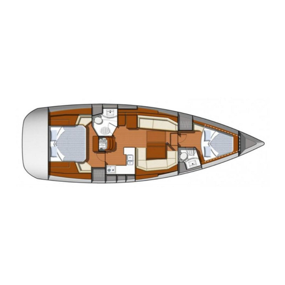
5.3, 5.4, 5.5 ISO 10 240 ACCOMMODATIONS MAINTENANCE FABRICS 71/132... - Page 76 5.3.1 ISO 10 240 72/132...
- Page 77 MAINTENANCE INSIDE - Take advantage of the fine weather to take the settee and berth cushions out. - Put the cushions vertically if you leave the boat for long. - Use blinds to protect the inside of the boat against UV rays. - Carefully remove all crumbs.
- Page 79 FABRICS ADVICE: Mark up each cover and foam when dismantling. STAIN REMOVAL - Remove as much stain as you can with a knife blade (from the edge towards the centre). - Dab with a clean rag. - Remove the stain with solvent on a clean rag. Never pour the solvent directly over the stain. - Rub with a clean and dry rag.
- Page 81 FABRICS 100% POLYESTER/DRALON JACQUARD If you cannot remove the fabric: - Clean with the vacuum cleaner. - Clean with synthetic foam (please refer to the product instructions). If you can remove the fabric: - Hand wash with an ordinary washing powder at 30° C. In both cases, dry cleaning is possible.
- Page 83 MAINTENANCE RECOMMENDATION The builder tested and approved a certain number of biodegradable cleaning and restoring products that protect both material and environment. The related technical data is available at your JEANNEAU dealer. 79/132...
-
Page 85: Plumbing
5.3, 5.5, 5.6 ISO 10 240 PLUMBING WATER TANK FILLING FRESH WATER SYSTEM GAS SYSTEM DRAINAGE SYSTEM SANITARY APPLIANCE OPERATION DRAWINGS AT THE END OF THE MANUAL 81/132... - Page 86 5.3.3 a); 5.3.3 g); 5.3.3 k) ISO 10 240 WATER AND GAS DISTRIBUTION 1. Valve to select tank 2. Flowmeter 3. Pressurized water unit 4. Expansion chamber 5. Bilge pump (refer to "Draining") 82/132...
-
Page 87: Water Tank Filling
WATER TANK FILLING In order to prevent any handling mistakes, never fill the water and fuel tanks at the same time. During filling, avoid handling contaminants near the fillers. Open and close the filler caps with the suitable key. Check the filler cap seals for condition during filling. The tanks are fitted with overflow outlets and vents. - Page 88 5.3.3 a); 5.3.3 g) ISO 10 240 SINK DRAINING 1. Thru-hull fitting with valve; Sink draining THRU-HULL FITTING Thru-hull fitting closed Thru-hull fitting open 84/132...
-
Page 89: Fresh Water System
FRESH WATER SYSTEM PRECAUTION - Never operate the water system equipment when the valve is closed or the tank is empty (the electrical equipment may be damaged). - Check the water filter for condition (refer to manufacturer's instructions). - Close the taps of empty tanks. GAS SYSTEM Refer to chapter 2, "Safety". - Page 90 5.3.3 a); 5.3.3 d); 5.3.3 g); 5.3.3 k) ISO 10 240 FORE WASHROOM 1. Thru-hull fitting with valve; Washbasin draining 1. Thru-hull fitting with valve; Heads 2. Thru-hull fitting with valve; Shower tray draining water intake 1.Thru-hull fitting with valve; WC evacuation 86/132...
-
Page 91: Drainage System
DRAINAGE SYSTEM Waste water from the sink, washbasins and heads is drained off by thru-hull fittings with ball valves (the valve is closed when the valve handle is perpendicular to the hose, the valve is open when the valve handle is in line with the hose). All the floors have holes (limber holes) for the water flow. - Page 92 5.3.3 a); 5.3.3 k) ISO 10 240 AFT WASHROOM 1. Thru-hull fitting with valve; Shower tray draining 1. Thru-hull fitting with valve; Heads 2. Thru-hull fitting with valve; Washbasin draining water intake 1.Thru-hull fitting with valve; WC evacuation 88/132...
-
Page 93: Sanitary Appliance Operation
SANITARY APPLIANCE OPERATION USE OF THE MARINE HEADS Before you use the heads, check that the water intake valve and draining valve are open. To empty the bowl: - Set the control lever of the pump slantwise (FLUSH). - Operate the pump. To dry the bowl: - Set the lever back vertical (DRY). - Page 94 SIMPLE TANK 1. Heads water intake hose with a thru-hull fitting and a valve 2. Tank draining hose with a thru-hull fitting and a valve 3. Heads filler 4. Tank vent hole 5. Waste holding tank (WHT) (about 45 l) 90/132...
- Page 95 USE OF MARINE HEADS EQUIPPED WITH A WASTE HOLDING TANK (WHT) - OPTIONAL EXTRA WARNING Ask for information about the laws in force in your country or your marina about discharging your waste waters into the sea. Open the water intake valve (ref. 1) (valve handle parallel to the pipe). In the case of a direct discharge into the sea: Open the draining valve (ref.
- Page 96 To empty the tank: - In an authorized area, open the draining valve (ref. 2). - In a marina equipped with a system to suck the waste waters, put the sucking hose into the tank through the deck filler (ref. 3). Start the pump of the sucking system. The filler caps are opened and closed with an appropriate key.
-
Page 97: Electric Systems
5.3, 5.4, 5.5, 5.6 ISO 10 240 ELECTRIC SYSTEMS BATTERY SWITCH BATTERIES OPERATION 230 V SYSTEM SHORE POWER MAST HARNESS CONNECTION ELECTRONICS DRAWINGS AND DIAGRAMS (AT THE END OF THE MANUAL) 93/132... - Page 98 5.3.3 b); 5.5.1 ISO 10 240 BATTERY SWITCH 1. Battery switch + House 2. Battery switch + Engine 3. Battery switch - 4. Windlass circuit breaker 94/132...
-
Page 99: Battery Switch
BATTERY SWITCH The electricity onboard is 12 V DC. The electrical system consists of service batteries. The batteries supply power to all the functions on board. The engine has its own battery. Switch on by turning the battery switches (12 V). PRECAUTION Switch off all the battery switches when the boat is unattended. - Page 101 MAINTENANCE RECOMMENDATION - Keep the batteries clean and dry in order to avoid premature wear. - Periodically check the electrolyte level. Add some distilled water if need be. - Have the acidity level of the battery checked if unused for long. - Tighten and maintain the terminal connectors lubricating them regularly with vaseline.
- Page 103 OPERATION The electrical switchboard does not require any routine maintenance . PRECAUTION Never leave the boat unattended when the electric fitting is on (except the safety equipments directly connected to the battery and protected by a circuit breaker). Disconnect the 230 V before you open the electric panel or cupboard. In case an electric appliance is not energized, check: - The main power supply (batteries, battery switches).
-
Page 104: Shore Power
5.3.3 b) 5.5.1 ISO 10 240 SHORE POWER 100/132... - Page 105 230 V SYSTEM (As far as possible) use electric appliances with double insulation or with three conductors (Neutral-Live wire-Ground). Connect the metallic covers or boxes of the electric appliances that are installed to the protective conductor of the boat (green conductor with yellow stripes). SHORE POWER DANGER Never let the end of the boat/shore supply cable hang in the water:...
-
Page 107: Diesel Engine
5.3, 5.4, 5.5, 5.6, ISO 10 240 DIESEL ENGINE FUEL TANKS FUEL FILTER CLOSING VALVE OF THE FUEL SYSTEM ENGINE VISIBILITY FROM THE STEERING STATION INSTRUMENT PANEL / CONTROL LEVER STUFFING BOX PROPELLER ANODE 103/132... -
Page 108: Engine Installation
5.3.3 c); 5.3.3 f); 5.3.3 k); 5.3.3 l) ISO 10 240 ENGINE INSTALLATION 1. Engine water valve 2. Fuel oil return pipe 3. Fuel pipe 4. Sea water filter 5. Exhaust pipe 6. Decanter prefilter 7. Closing valve of the fuel system 8. -
Page 109: Fuel Tanks
FUEL TANKS FILLING Take the general precautions stated in chapter 7 about the water tank filling. Fill the fuel tank using the filler. In order to protect the deck from possible fuel splash, wet the area around the filler with sea water before you remove the filler cap. In case of splashes, rinse the deck thoroughly (after fitting back the filler cap). - Page 110 5.3.3 c); 5.3.3 k); 5.5.1 ISO 10 240 FUEL VALVE 1. Fuel oil valve for engine 106/132...
-
Page 111: Fuel Filter
FUEL FILTER The engine running problems may have different origins, among which dirty fuel. The injection pump may wear out if there is water in the system. The water results either from the condensation resulting from an insufficiently filled tank, or from a filler cap either not closed properly or with a damaged seal. - Page 112 5.3.2; 5.3.3 k); 5.3.3 l); 5.5.1 ISO 10 240 IN BOARD ENGINE Fore access Stern access 1. Anti-siphonage bend 1. Filter for engine cooling water 2. Filter for engine cooling water 3. To water inlet thru-hull fitting 1. Thru-hull fitting with valve; Engine water valve 108/132...
- Page 113 ENGINE RECOMMENDATION Carefully read the instructions given with your boat. These instructions give detailed explanations on proper operation of the engine. PRECAUTION Never run the engine when the boat is hauled out. ACCESS TO THE ENGINE You have access to the engine via the companionway hatch. You can check the main parts thanks to side hatches.
- Page 115 ENGINE WATER VALVE The water inlet valve of the engine is essential in the engine operation. - Keep the strainer under the hull as clean as possible. - Brush the strainer when the boat is careened. - Do not cover the strainer with antifouling paint. This valve must be open before starting the engine (risk of quick damage of the exhaust muffler and of great damage of the engine).
-
Page 117: Engine Operation
ENGINE OPERATION Before starting the engine: - Turn on the fuel valve. - Open the valve of the engine cooling system and the valve of the stuffing box. - Operate the battery switches and energize the electric system. - Disengage the reverse gear (it will make the acceleration possible when in neutral). WARNING Never switch off or de-energize the electric system when the engine is running. - Page 118 POSITION OF THE LEAD LINES Lead lines (Log and speedometer) 114/132...
- Page 119 VISIBILITY FROM THE STEERING STATION The international regulations to prevent collision at sea (COLREG) and the course regulations make mandatory a permanent and proper surveillance and the respect of priority. Make sure there is no other boat on your way. The visibility from the steering station may be obstructed in the following conditions: - Load and load distribution.
- Page 120 5.3.2 ISO 10 240 STUFFING BOX Stuffing box 5. Stern frame 1. Anode 6. Stuffing box 2. Propeller 7. Connecting device 3. P bracket 4. Propeller shaft 116/132...
-
Page 121: Stuffing Box
STUFFING BOX You have access to the stuffing box through the central technical compartment behind the engine. Lubricate the seal every 200 running hours (or at least once a year). Use 1 cm at each lubrication. ADVICE: Apply the grease the manufacturer recommends in his instructions. After launching the boat, drive the air out from the sleeve pinching it with your fingers. -
Page 123: Launching
5.2, 5.3, 5.4 ISO 10 240 LAUNCHING LAUNCHING RECOMMENDATIONS STEPPING THE MAST 119/132... -
Page 125: Launching Recommendations
LAUNCHING RECOMMENDATIONS A lot of skill and care is required to commission your JEANNEAU boat. The proper working of all your boat equipments in the future results from the quality of the commissioning operations. The initial launching and the first tests of the different equipments shall be carried out by your JEANNEAU dealer or agent so you can expect to enjoy the warranty in case of some equipment failure. -
Page 127: Stepping The Mast
HOISTING - Install a fore rope, a rear rope and fenders. - When craning, check that no device is crushed by the belts (sounder, speedometer, shaft, etc.). - Mark the belt position with adhesive tape on the toe rail (most of the boats are already fitted with these stickers). -
Page 129: Winter Storage
5.3, 5.4, 5.5 ISO 10 240 WINTER STORAGE LAYING UP PROTECTION AND MAINTENANCE 125/132... - Page 131 LAYING UP - Take ashore all the ship's log, the ropes that are not used for mooring, the galley equipment, supplies, clothes, the safety equipment, batteries, the gas cylinder. - Mark again the safety equipment, check the expiration dates, have the liferaft overhauled. - Take advantage of this laying up to draw up a complete inventory of the equipment.
- Page 133 ENGINE The engine winterization shall be carried out by a professional. Depending on the boat location, afloat or ashore, winterization is different. Here are a few major tasks to carry out: Afloat - Drain the cooling system and fill it with antifreeze. - Switch off the battery switches, lubricate the terminals with vaseline and check the battery voltage.
-
Page 135: Personal Notes
Personal notes CHANTIERS JEANNEAU - BP 529 - 85505 LES HERBIERS cedex - FRANCE Tel. (33) 02 51 64 20 20 - Fax (33) 02 51 67 37 65 Internet : http://www.jeanneau.com(fr). 131/132...
Need help?
Do you have a question about the SUN ODYSSEY 42 DS and is the answer not in the manual?
Questions and answers