
Related Manuals for Miller SuitCase 8VS


Summary of Contents for Miller SuitCase 8VS
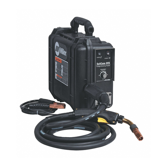
- Page 1 OM-1599 200 624E January 2003 Processes MIG (GMAW) Welding Flux Cored (FCAW) Welding Description Wire Feeder SuitCase 8VS Visit our website at www.MillerWelds.com...
- Page 2 We know you don’t have time to do it any other way. That’s why when Niels Miller first started building arc welders in 1929, he made sure his products offered long-lasting value and superior quality.
-
Page 3: Table Of Contents
TABLE OF CONTENTS SECTION 1 – SAFETY PRECAUTIONS - READ BEFORE USING ......1-1. - Page 4 Declaration of Conformity for European Community (CE) Products NOTE This information is provided for units with CE certification (see rating label on unit). Miller Electric Mfg. Co. Manufacturer’s Name: 1635 W. Spencer Street Manufacturer’s Address: Appleton, WI 54914 USA SuitCase 8VS...
-
Page 5: Section 1 - Safety Precautions - Read Before Using
SECTION 1 – SAFETY PRECAUTIONS - READ BEFORE USING som _nd_7/02 1-1. Symbol Usage Means Warning! Watch Out! There are possible hazards with this procedure! The possible hazards are shown in the adjoining symbols. This group of symbols means Warning! Watch Out! possible Y Marks a special safety message. - Page 6 ARC RAYS can burn eyes and skin. BUILDUP OF GAS can injure or kill. D Shut off shielding gas supply when not in use. Arc rays from the welding process produce intense D Always ventilate confined spaces or use visible and invisible (ultraviolet and infrared) rays that can burn eyes and skin.
-
Page 7: Additional Symbols For Installation, Operation, And Maintenance
1-3. Additional Symbols For Installation, Operation, And Maintenance FIRE OR EXPLOSION hazard. MOVING PARTS can cause injury. D Do not install or place unit on, over, or near D Keep away from moving parts such as fans. combustible surfaces. D Keep all doors, panels, covers, and guards D Do not install unit near flammables. -
Page 8: Principal Safety Standards
1-4. Principal Safety Standards Safety in Welding, Cutting, and Allied Processes, ANSI Standard Z49.1, Boulevard, Rexdale, Ontario, Canada (phone: from American Welding Society, 550 N.W. LeJeune Rd, Miami FL 33126 800–463–6727 or in Toronto 416–747–4044, website: www.csa–in- (phone: 305-443-9353, website: www.aws.org). ternational.org). -
Page 9: Signification Des Symboles
SECTION 1 – CONSIGNES DE SÉCURITÉ – À LIRE AVANT UTILISATION som _nd_fre 7/02 1-1. Signification des symboles Signifie « Mise en garde. Faire preuve de vigilance. » Cette procédure présente des risques identifiés par les symboles adjacents aux directives. Ce groupe de symboles signifie «... - Page 10 LES RAYONS DE L’ARC peuvent cau- LES ACCUMULATIONS DE GAZ peu- ser des brûlures oculaires et cuta- vent causer des blessures ou même nées. la mort. Le rayonnement de l’arc génère des rayons visibles et D Couper l’alimentation en gaz protecteur en cas de invisibles intenses (ultraviolets et infrarouges) suscep- non utilisation.
- Page 11 1-3. Autres symboles relatifs à l’installation, au fonctionnement et à l’entretien de l’appareil. Risque D’INCENDIE OU D’EXPLO- LES ORGANES MOBILES peuvent SION causer des blessures. D Ne pas placer l’appareil sur une surface inflam- D Se tenir à l’écart des organes mobiles comme les mable, ni au–dessus ou à...
-
Page 12: Principales Normes De Sécurité
1-4. Principales normes de sécurité Safety in Welding, Cutting, and Allied Processes, norme ANSI Z49.1, Rexdale, Rexdale (Ontario) Canada M9W 1R3 (téléphone : (800) de l’American Welding Society, 550 N.W. LeJeune Rd, Miami FL 33126 463–6727 ou à Toronto : (416) 747–4044, site Web : www.csa–interna- (téléphone : (305) 443–9353, site Web : www.aws.org). -
Page 13: Section 2 - Definitions
SECTION 2 – DEFINITIONS 2-1. Warning Label Definitions Warning! Watch Out! There are possible hazards as shown by the symbols. Drive rolls can injure fingers Welding wire and drive parts are at welding voltage during operation – keep hands and metal objects clear. -
Page 14: Manufacturer's Rating Label For Ce Products
2-2. Manufacturer’s Rating Label For CE Products For label location see Section 4-1. S/N: IP 23 ST-181 678 2-3. Symbols And Definitions NOTE Some symbols are found only on CE products. Output Input Amperes Volts Degree Of Protec- Duty Cycle Wire Feed Percent tion... -
Page 15: Section 3 - Installation
SECTION 3 – INSTALLATION 3-1. Specifications Welding Input Type of Wire Feed Wire Type Max. Wire Power Welding Overall Input Speed Spool Weight Source Circuit Rating Dimensions Power Range Diameter Capacity Type Rating Solid Steel: .023 – .062 in Length: 15-5/8 in Constant 50 –... -
Page 16: Installing And Aligning Wire Guide And Drive Rolls
3-3. Installing And Aligning Wire Guide And Drive Rolls Installing Wire Guide And Drive Rolls: Drive Roll Nut Drive Roll Carrier Turn nut one click until lobes of nut line up with lobes of drive roll carrier. Drive Roll Slide drive roll onto drive roll carrier. Turn nut one click. -
Page 17: Connecting Welding Gun And Voltage Sensing Lead
3-4. Connecting Welding Gun And Voltage Sensing Lead Gun Securing Knob Gun Block Gun Outlet Wire Guide Loosen knob, insert gun end into block. Position outlet wire guide as close as possible to drive rolls with- out touching. Tighten knob. Gun Trigger Plug Gun Trigger Receptacle Voltage Sensing Clamp... -
Page 18: Connecting Weld Cable
3-6. Connecting Weld Cable User-Suppled Weld Cable Follow wire manufacturer’s recom- Internal Side View mendations for weld cable polarity. User-Suppled Male Connector From Wire Feeder User-Suppled Female Connector Push female connector over male connector, and turn 1/4 turn clock- wise. Ref. -
Page 19: Section 4 - Operation
SECTION 4 – OPERATION 4-1. Controls For Non-CE Models Power Control Switch Trigger Hold Switch (Optional) This unit offers an optional trigger hold function, which is turned On or Off with a front panel toggle switch. Depress the upper part of the switch (turns trigger hold On) to weld with- out holding gun trigger throughout the weld cycle. -
Page 20: Controls For Ce Models
4-2. Controls For CE Models Power Control Switch Trigger Hold Switch Depress the upper part of the switch (turns trigger hold On) to weld without holding gun trigger throughout the weld cycle. To start weld, press and release gun trigger. To end weld, press and release gun trigger. -
Page 21: Section 5 - Maintenance & Troubleshooting
SECTION 5 – MAINTENANCE & TROUBLESHOOTING 5-1. Routine Maintenance Y Disconnect power Maintain more often before maintaining. during severe conditions. 3 Months Replace Damaged Or Replace Damaged Unreadable Gas Hose Labels Repair Or Replace Cracked Cables And Cords 6 Months Clean Blow Out Or Drive... -
Page 22: Troubleshooting
5-3. Troubleshooting Trouble Remedy Wire does not feed; open-circuit voltage Check circuit breaker CB1. Reset CB1. available. Unit overheated. Allow unit to cool. Check sensing lead connection. Check gun trigger plug connection. Check gun trigger. See gun Owner’s Manual. Wire feeds erratically. Readjust hub tension. -
Page 23: Section 6 - Electrical Diagrams
SECTION 6 – ELECTRICAL DIAGRAMS 203 029–B Figure 6-1. Circuit Diagram For Wire Feeder OM-1599 Page 19... - Page 24 Notes OM-1599 Page 20...
-
Page 25: Section 7 - Parts List
SECTION 7 – PARTS LIST Hardware is common and not available unless listed. 802 675-B Figure 7-1. Complete Assembly OM-1599 Page 21... - Page 26 Item Dia. Part Description Mkgs. Quantity Figure 7-1. Complete Assembly ....202 695 Nut, Hub ............
- Page 27 Item Dia. Part Description Mkgs. Quantity Figure 7-1. Complete Assembly (Continued) ... . . 172 732 Cable, Sensing 15 Ft ..........
- Page 28 Table 7-1. Drive Roll & Wire Guide Kits (2 Drive Roll) NOTE Base selection of drive rolls upon the following recommended usages: 1. V-Grooved rolls for hard wire. 2. U-Grooved rolls for soft and soft shelled cored wires. 3. U-Cogged rolls for extremely soft shelled wires (usually hard surfacing types). 4.
- Page 29 Notes OM-1599 Page 25...
- Page 30 Notes OM-1599 Page 26...
- Page 31 Effective January 1, 2002 (Equipment with a serial number preface of “LC” or newer) This limited warranty supersedes all previous Miller warranties and is exclusive with no other Warranty Questions? guarantees or warranties expressed or implied. Call LIMITED WARRANTY – Subject to the terms and conditions APT, ZIPCUT &...
- Page 32 Distributor Address City State For Service Call 1-800-4-A-Miller or see our website at www.MillerWelds.com to locate a DISTRIBUTOR or SERVICE AGENCY near you. Always provide Model Name and Serial/Style Number. Contact your Distributor for: Welding Supplies and Consumables Options and Accessories...
Need help?
Do you have a question about the SuitCase 8VS and is the answer not in the manual?
Questions and answers