Table of Contents
Advertisement
Quick Links
Advertisement
Table of Contents

Related Manuals for Tandberg Data LTO-5


Summary of Contents for Tandberg Data LTO-5
- Page 2 Further, Tandberg Data Corporation reserves the right to revise this publication without obligation of Tandberg Data Corporation to notify any person or organization of such revision or changes. TRADEMARK NOTICES: Tandberg Data Corporation trademarks: Tandberg Data, Exabyte, the Exabyte Logo, EZ17, M2, SmartClean, VXA, and VXAtape are registered trademarks;...
-
Page 3: Table Of Contents
..Attach mounting hardware ................21 ..Install drive ....................22 ..Connect SAS and power cables to an LTO-5 SAS tape drive ...... 24 ..Connect SAS and power cables to an LTO-4 SAS tape drive ...... 25 ..Connect FC and power cables ..............28 ..Connect SCSI and power cables .............. - Page 4 ..Cleaning cartridges ................. 53 ..Data cartridges ..................54 ..WORM data cartridges .................. 54 ..LTO-5 tape drives and partitioning ..............55 ..LTO–5 and LTO-4 tape drives and encryption ..........55 ..When should I use encryption? .............. 56 ..How do I enable encryption? ..............56 ..When will I be asked to enter the key? ...........
- Page 5 Installing a full-height tape drive ..........23 Figure 2-4 Installing a half-height tape drive ..........23 Figure 2-5 Connecting cables to the full-height LTO-5 tape drive .... 25 Figure 2-6 Connecting cables to the half-height LTO-5 tape drive ... 25 Figure 2-7 Connecting cables to the LTO-4 full-height tape drive ....
- Page 6 Figure 3-2 Connecting the cables to a full-height tape drive ....39 Figure 3-3 Connecting the cables to a half-height tape drive ....39 Figure 5-1 Front view of full-height LTO–5 external tape drive ....43 Figure 5-2 Front view of full-height LTO–4 external tape drive ....44 Figure 5-3 Front view of half-height LTO–5 external tape drive ....
- Page 7 Tables Table 1 Document conventions ............IX Table 1-1 FC drive interface speeds ............12 Table 1-2 SAS drive interface speeds ............. 12 Table 1-3 Supported SCSI bus types ............14 Table 5-1 Ready, Drive Error, Tape Error and Clean LED se- quences ..................
- Page 8 Notes...
-
Page 9: About This Guide
About this guide This guide provides information about: • Installing the LTO tape drive • Using the LTO tape drive • Troubleshooting the LTO tape drive Intended audience This guide is intended for users who install, operate and maintain the LTO tape drive. -
Page 10: Technical Support
About this guide Warning Indicates that failure to follow directions could result in bodily harm or death. Indicates that failure to follow directions could result Caution in damage to equipment or data. Important Provides clarifying information or specific instructions. Note: Provides additional information. -
Page 11: Before You Start
16 Supported models This guide describes how to install and operate the following LTO tape drive models: • LTO-5 SAS and FC internal tape drives • LTO-5 SAS external tape drives • LTO-4 SAS, FC and SCSI internal tape drives •... -
Page 12: How Do I Connect The Drive To My Server
SAS components are required. Always verify that the SAS cable you are using is rated for the data transfer speed of the interface of your components. SAS cables described as "equalized" may not support 6 Gb/s data rates and should not be used with LTO-5 1019... -
Page 13: Interface Specifications And Requirements For Scsi Drives
How do I connect the drive to my server? tape drives unless these cables are verified for 6 Gb/s data rates. For optimum performance, only use cables of the length specified as qualified for your products. Interface specifications and requirements for SCSI drives Use an LVDS-compatible ribbon cable to connect the tape drive to a spare 68-pin, high density (HD), wide SCSI connector on the host server. - Page 14 Chapter 1–Before you start Table 1-3 Supported SCSI bus types SCSI Bus Type Supported Ultra160 LVD, Ul- Yes. These are recommended configurations. tra320 LVD Ultra2 LVD, Ultra Yes. These are supported, but performance may Wide LVD be impaired. Ultra wide, single- Yes.
-
Page 15: Your Lto Tape Drive
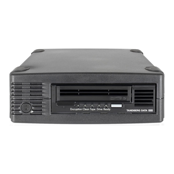
Your LTO tape drive Your LTO tape drive 1. On/Off switch (external drives 5. Drive Error LED only) 2. Eject button 6. Tape Error LED 3. Reset 7. Clean LED 4. Ready LED 8. Encryption LED Figure 1-1 Front view of full-height LTO–5 external tape drive 1. -
Page 16: Power Specifications
Chapter 1–Before you start Power specifications Power for the LTO-5 SAS internal tape drive is supplied through the SAS cable. For all earlier models of LTO SAS tape drive and for all SCSI and FC tape drives, a separate power cable is required, see http:// www.tandbergdata.com. -
Page 17: Enabling Encryption
Backup software Enabling encryption The LTO-5 and LTO–4 tape drive includes hardware capable of performing data encryption while writing and data decryption while reading, both at full speed. This is only possible with Ultrium 3 TB and 1.6 TB media, respectively. - Page 18 Chapter 1–Before you start Notes 1019...
-
Page 19: Installing An Internal Lto Tape Drive
“Attach mounting hardware” on page 21 • “Install drive” on page 22 • “Connect SAS and power cables to an LTO-5 tape drive” on page 24 • “Connect SAS and power cables to an LTO-4 tape drive” on page 25 •... - Page 20 Chapter 2–Installing an internal LTO tape drive from the mains power supply while you install the drive. Static electricity can damage electronic components. Caution Always wear an antistatic wriststrap if one is available. If not, after you have disconnected power from the server and removed the cover, touch a bare metal part of the chassis.
-
Page 21: Attach Mounting Hardware
Attach mounting hardware Attach mounting hardware If your server requires special rails or other hardware to install the tape drive, mount them on the tape drive now. If your server does not require special mounting hardware, proceed to “Install drive” on page 22 now. Please check your server documentation to ascertain the correct method of mounting, and to check whether mounting hardware is provided with the server or must be purchased separately. -
Page 22: Install Drive
Chapter 2–Installing an internal LTO tape drive Figure 2-1 Attaching mounting rails to a full-height tape drive 1. M3 mounting screws 2. M3 offset mounting screws Figure 2-2 Attaching locating screws to a half-height tape drive Install drive If cable access for the tape drive bay is awkward, it may Note: be easier to access power and other connections if the tape drive is installed in the top bay. -
Page 23: Figure 2-3 Installing A Full-Height Tape Drive
Install drive Figure 2-3 Installing a full-height tape drive Figure 2-4 Installing a half-height tape drive Note: The illustration shows a server that uses mounting rails. If your server does not use mounting hardware, check that the holes in the chassis are aligned with the holes in the side of the tape drive. -
Page 24: Connect Sas And Power Cables To An Lto-5 Sas Tape Drive
Chapter 2–Installing an internal LTO tape drive Connect SAS and power cables to an LTO-5 SAS tape drive Important A SAS HBA and appropriate SAS cable are required. LTO-5 tape drives require a SAS cable with power connector. “Connect SAS and power cables to an LTO-4 tape drive”... -
Page 25: Connect Sas And Power Cables To An Lto-4 Sas Tape Drive
Connect the SAS cable to the tape drive, as illustrated below. 1. Power connector 2. SAS connector Figure 2-5 Connecting cables to the full-height LTO-5 tape drive 1. SAS connector 2. Power connector Figure 2-6 Connecting cables to the half-height LTO-5 tape drive Now go to “Secure the... - Page 26 Chapter 2–Installing an internal LTO tape drive If you are installing a FC tape drive, see “Connect FC and power cables” on page 28. If you are installing a SCSI tape drive, see “Connect SCSI and power cables” on page 30. If a SAS HBA is not already installed in the server, follow the instructions supplied with the HBA to install it and any associated drivers before you install the tape drive.
-
Page 27: Figure 2-7 Connecting Cables To The Lto-4 Full-Height Tape Drive
LTO-3 tape drives because this may damage the drive. Always use a spare power cable from the server's internal power supply. (This caution does not apply to LTO-5 tape drives.) 1. SAS connector 2. Power connector Figure 2-7 Connecting cables to the LTO-4 full-height tape drive 1. -
Page 28: Connect Fc And Power Cables
Chapter 2–Installing an internal LTO tape drive Figure 2-8 Connecting cables to the LTO-4 half-height tape drive Now go to “Secure the drive” on page 33. Connect FC and power cables A standard 4–pin power connector is used to supply the 5V and 12V power to the tape drive. -
Page 29: Figure 2-9 Attaching The Fibre Channel Cable To A Full-Height Tape Drive
Connect FC and power cables Remove the FC port caps if necessary. Attach one end of the Fibre Channel cable to The FC optical connector on the tape drive as shown below. 1. FC optical connector Port A 2. FC optical connector Port B (standard) (optional) 3. -
Page 30: Connect Scsi And Power Cables
Chapter 2–Installing an internal LTO tape drive Connect SCSI and power cables To support the high performance of the tape drive it is important that you connect to a recommended SCSI bus and use a suitably-rated SCSI cable. Check the drive's SCSI ID Your DAT drive is shipped with a default SCSI ID of 2. -
Page 31: Connect The Cables
Connect SCSI and power cables Change the tape drive's SCSI ID, if necessary. The SCSI ID is set using jumpers on a set of pins at the rear of the drive, as illustrated. Use tweezers or small pliers to move the jumpers to the pattern corresponding to the ID you want. -
Page 32: Figure 2-12 Attaching The Scsi And Power Cables To A Full-Height Tape Drive
Chapter 2–Installing an internal LTO tape drive Attach a spare power cable from the server's internal power supply to the power connector. Attach a spare connector on the server's built-in SCSI bus or HBA's SCSI ribbon cable to the SCSI connector of the drive, as shown in the following figure. -
Page 33: Secure The Drive
Secure the drive If the drive is the last device on the SCSI chain, make sure that the SCSI cable is terminated correctly. Termination must be present at two and ONLY two Note: positions on the SCSI bus—at the beginning of the SCSI bus and at the end of the SCSI bus. -
Page 34: Reboot The Server
Chapter 2–Installing an internal LTO tape drive Secure the drive, as described in your server documentation. The following diagrams are examples only. Plastic rail Server latch Figure 2-13 Securing full-height drive, mounting hardware used M3 screws Figure 2-14 Securing half-height drive, no mounting hardware used Ensure blanking plates are in place over empty bays and replace the cover on the server. - Page 35 Reboot the server If this does not resolve the problem, refer to “Troubleshooting” on page 61 for further guidelines. May 2010...
- Page 36 Chapter 2–Installing an internal LTO tape drive Notes 1019...
-
Page 37: Installing An External Lto Tape Drive
Installing an external LTO tape drive This chapter describes how to connect your SAS tape drive to an external SAS port on the host controller or new HBA. (The FC and SCSI tape drives are not available as external models.) If you are installing an internal LTO tape drive, please refer to “Installing an internal tape drive ”... -
Page 38: Figure 3-1 Connecting The Sas Cable To The Server
Chapter 3–Installing an external LTO tape drive Connect the purchased SAS cable to the external SAS connector on the SAS HBA. 1. SAS connector on server Figure 3-1 Connecting the SAS cable to the server 1019... -
Page 39: Figure 3-2 Connecting The Cables To A Full-Height Tape Drive
Connecting the tape drive to an external SAS port Connect the SAS and power cables to the tape drive and plug the other end of the power cable into the power outlet. Figure 3-2 Connecting the cables to a full-height tape drive 1. -
Page 40: Reboot The Server
Chapter 3–Installing an external LTO tape drive Reboot the server Switch on the tape drive and power up the server. The power on/off switch is on the front panel. Watch the boot screen carefully after installation. If there are any error or unexpected messages go back and check the cabling carefully. -
Page 41: Verify Installation
Verify installation Once you have installed the drive hardware, check that drivers have been installed correctly and you have the correct version of backup software, and verify that the tape drive is functioning properly before you store your valuable data. Switch on the drive and the server. - Page 42 Chapter 4–Verify installation Carry out a backup and restore test to check that the drive can write data to tape. Use a blank cartridge. Native backup applications can be used to check basic tape drive operation, but they will not support all the advanced features of your tape drive.
-
Page 43: Understanding The Leds
Understanding the LEDs In this chapter: • “Front view of full-height LTO tape drive with LEDs” on page 43 • “Front view of half-height LTO tape drive with LEDs” on page 44 • “Understanding LED sequences” on page 45 Front view of full-height LTO tape drive with LEDs 1. -
Page 44: Front View Of Half-Height Lto Tape Drive With Leds
Chapter 5–Understanding the LEDs 1. On/Off switch (external drives 5. Drive Error LED only) 2. Eject button 6. Tape Error LED 3. Reset 7. Clean LED 4. Ready LED Figure 5-2 Front view of full-height LTO–4 external tape drive Front view of half-height LTO tape drive with LEDs 1. -
Page 45: Understanding Led Sequences
Understanding LED sequences 1. Cassette door 5. Drive LED 2. On/Off switch (external drives 6. Ready LED only) 3. Clean LED 7. Eject button 4. Tape LED Figure 5-4 Front view of half-height LTO–4 and LTO–3 external tape drive Understanding LED sequences The LED sequences in the following table relate to the Ready, Drive (Error), Tape (Error) and Clean LEDs. - Page 46 Chapter 5–Understanding the LEDs Table 5-1 Ready, Drive Error, Tape Error and Clean LED sequences LED Sequence Cause Action required Make sure the drive is switched on. The power on/off switch on an external drive incorporates a green LED. Check the power cable connection and replace the Drive may not have cable if necessary.
- Page 47 Understanding LED sequences LED Sequence Cause Action required Load the Ultrium cleaning cartridge. See “Cleaning cartridges” on page 53 for supported cartridges and The drive requires instructions. Clean FLASHES. cleaning. If the Clean LED is still flashing when you load a new or known good data cartridge after cleaning, call for service.
-
Page 48: Encryption Led, Lto-5 Models Only
Chapter 5–Understanding the LEDs LED Sequence Cause Action required Drive and Ready Power cycle or reset the drive. ON with Tape and The drive has a Upgrade the firmware. If the Clean OFF. firmware error. condition persists, call for Alternates service. -
Page 49: Operating Your Tape Drive
Operating your tape drive In this chapter: • “Loading a cartridge” on page 50 • “Unloading a cartridge” on page 51 • “Removing power from the drive” on page 52 May 2010... -
Page 50: Loading A Cartridge
Chapter 6–Operating your tape drive Loading a cartridge 1. Arrow indicates leading direction 2. Label area 3. Ready LED Figure 6-1 Inserting a cartridge into a full-height tape drive 1. Arrow indicates leading direction 2. Cartridge door 3. Label area 4. -
Page 51: Unloading A Cartridge
Unloading a cartridge Insert the cartridge into the slot in the front of the drive with the white arrow uppermost and facing the drive door. Apply gentle pressure until the drive takes the cartridge and loads it. The Ready light flashes green while the drive performs its load sequence. -
Page 52: Removing Power From The Drive
Chapter 6–Operating your tape drive Press the Eject button on the front panel. Figure 6-3 Ejecting a cartridge from a full-height tape drive 1. Eject button Figure 6-4 Ejecting a cartridge from a half-height tape drive The drive will complete its current task, rewind the tape to the beginning, and eject the cartridge. -
Page 53: Use The Correct Media
In this chapter: • “Cartridges” on page 53 • “WORM data cartridges” on page 54 • “LTO-5 and LTO-4 tape drives and encryption” on page 55 • “Write protecting cartridges” on page 57 • “Cleaning the tape drive” on page 58 •... -
Page 54: Data Cartridges
LTO-5 read only once/read once/read many many read/write read/write not suppor- write write not suppor- LTO-4 read only once/read once/read... -
Page 55: Lto-5 Tape Drives And Partitioning
LTO–5 and LTO-4 tape drives and encryption The LTO-5 and LTO–4 tape drive includes hardware capable of performing data encryption at full speed while writing data, and decrypting when reading. Encryption is the process of changing data into a form that cannot be read until it is deciphered, protecting the data from unauthorized access and use. -
Page 56: When Should I Use Encryption
Chapter 7–Use the correct media When should I use encryption? Your company policy will determine when you need to use encryption. For example, it may be mandatory for company confidential and financial data, but not for personal data. Company policy will also define how encryption keys should be generated and managed. -
Page 57: Does Encryption Affect Tape Drive Performance
(R/W and WORM). Encrypted Ultrium 3 TB and 1.6 TB tapes can be read on any compatible LTO tape drive that supports hardware encryption. (LTO-5 tape drives can read and write encrypted Ultrium 3 TB media and Ultrium 1.6 TB media;... -
Page 58: Cleaning The Tape Drive
Chapter 7–Use the correct media • To write protect a cartridge, push the switch to the right to prevent any data recording on the cartridge. Note the padlock on the tab that indicates that the cartridge is protected. • To write enable a cartridge, push the switch to the left to allow data re- cording on the cartridge. -
Page 59: Handling Cartridges
Handling cartridges The drive will carry out its cleaning cycle and eject the cartridge on completion (which can take up to 5 minutes). During the cleaning cycle the orange Clean LED will be on solidly and the green Ready LED will flash. - Page 60 Chapter 7–Use the correct media Notes 1019...
-
Page 61: Troubleshooting
Troubleshooting In this chapter: • “General Procedure” on page 61 • “Optimizing performance” on page 63 • “Problems with cartridges” on page 64 General Procedure If a problem occurs, the first step is to try to establish whether the problem lies with the cartridge, the drive, the host computer and connections, or the way the system is being operated. - Page 62 Use the correct media type, for example: • Ultrium 3 TB RW and Ultrium 3 TB WORM tape cartridges for use with LTO-5 tape drives. • Ultrium 1.6 TB RW and Ultrium 1.6 TB WORM tape cartridges for use with LTO-4 tape drives.
-
Page 63: Optimizing Performance
Optimizing performance If the problem persists, check the environmental conditions against the specified limits, see Table 8-1 on page 62 or refer to http:// www.tandbergdata.com. Perhaps move the drive to a more suitable site. Has a new operating system been installed in the host computer? Has new backup software been installed? The problem could lie with the host or the software. -
Page 64: Problems With Cartridges
Chapter 8–Troubleshooting Problems with cartridges If you experience any problems using LTO branded cartridges, check: • The cartridge case is intact and that it contains no splits, cracks or damage. • The cartridge has been stored at the correct temperature and humidity. This prevents condensation. -
Page 65: The Drive Will Not Accept The Cartridge (Or Ejects It Immediately)
Problems with cartridges at the time, data may be lost and the cartridge will not have an EOD, which means that subsequent restores are likely to fail. Discard the cartridge. The drive will not accept the cartridge (or ejects it immediately) The cartridge may have been damaged, for example dropped, or the drive may have a fault. - Page 66 Chapter 8–Troubleshooting Notes 1019...
-
Page 67: Index
compatibility backup software, 16 connecting FC cables internal drive, 28 connecting power cable external drive, 39 connecting SAS cables external drive, 37 internal drive, 24, 25 Index connecting SCSI cables internal drive, 30 conventions document, IX text symbols, X audience, IX data cartridges, 54 default SCSI... - Page 68 Index inserting cartridges, 50 SCSI ID install drive, 22 default, 30 installation secure drive, 33 attach mounting hardware, 21 supported models, 11 connect cables (external), 37 symbols in text, X connect cables (internal), 24, 25, 28, 30 external drive, 37 tape drive guidelines, 12 cleaning, 58...
Need help?
Do you have a question about the LTO-5 and is the answer not in the manual?
Questions and answers