
Related Manuals for Thermal Dynamics 42 CUTMASTER


Summary of Contents for Thermal Dynamics 42 CUTMASTER
- Page 1 ™ CUTMASTER PLASMA CUTTING SYSTEM Art # A-09347_AE Operating Manual Rev. AD Date: November 22, 2011 Manual # 0-5141 Operating Features: PHASE...
- Page 2 Pacific) www.thermal-dynamics.com (Americas and Europe). This Operating Manual has been designed to instruct you on the correct use and operation of your Thermal Dynamics product. Your satisfaction with this product and its safe operation is our ultimate concern. Therefore please take the time to read the entire manual, especially the Safety Precautions.
- Page 3 Manufacturer assumes no liability for its use. Plasma Cutting Power Supply CutMaster™ 42 SL40 Torch™ Operating Manual Number 0-5141 Published by: Thermal Dynamics Corporation 82 Benning Street West Lebanon, New Hampshire, USA 03784 (603) 298-5711 www.thermal-dynamics.com Copyright 2010, 2011 by Thermadyne Corporation All rights reserved.
- Page 4 TABLE OF CONTENTS...
-
Page 5: Table Of Contents
TABLE OF CONTENTS SECTION 1: GENERAL INFORMATION ........................ 1-1 1.01 Notes, Cautions and Warnings ................. 1-1 1.02 Important Safety Precautions ................... 1-1 1.03 Publications ......................1-3 1.04 Note, Attention et Avertissement ................1-4 1.05 Precautions De Securite Importantes ............... 1-4 1.06 Documents De Reference .................. - Page 6 TABLE OF CONTENTS SECTION 6: PARTS LISTS ........................... 6-1 6.01 Introduction ......................6-1 6.02 Power Supply Replacement Parts ................6-2 APPENDIX 1: CIRCUIT DIAGRAM .......................... A-1...
-
Page 7: General Information
CUTMASTER 42 SECTION 1: • The kinds of fumes and gases from the plasma arc depend on the kind of metal being used, coatings on the metal, and the GENERAL INFORMATION different processes. You must be very careful when cutting or welding any metals which may contain one or more of the following: Antimony Chromium... - Page 8 CUTMASTER 42 • Provide a fire watch when working in an area where fire hazards may exist. • Hydrogen gas may be formed and trapped under aluminum PLASMA ARC RAYS workpieces when they are cut underwater or while using a water Plasma Arc Rays can injure your eyes and burn your skin. The plasma table.
-
Page 9: Publications
CUTMASTER 42 1.03 Publications 10. NFPA Standard 51B, CUTTING AND WELDING PROCESSES, obtainable from the National Fire Protection Association, Bat- Refer to the following standards or their latest revisions for more terymarch Park, Quincy, MA 02269 information: 11. CGA Pamphlet P-1, SAFE HANDLING OF COMPRESSED GASES 1. -
Page 10: Note, Attention Et Avertissement
CUTMASTER 42 1.04 Note, Attention et Avertissement • Utilisez un appareil respiratoire à alimentation en air si l’aération fournie ne permet pas d’éliminer la fumée et les gaz. Dans ce manuel, les mots “note,” “attention,” et “avertissement” • Les sortes de gaz et de fumée provenant de l’arc de plasma sont utilisés pour mettre en relief des informations à caractère dépendent du genre de métal utilisé, des revêtements se trouvant important. - Page 11 CUTMASTER 42 BRUIT INCENDIE ET EXPLOSION Le bruit peut provoquer une perte permanente de l’ouïe. Les procédés Les incendies et les explosions peuvent résulter des scories chaudes, de soudage à l’arc de plasma peuvent provoquer des niveaux sonores des étincelles ou de l’arc de plasma. Le procédé à l’arc de plasma produit du métal, des étincelles, des scories chaudes pouvant supérieurs aux limites normalement acceptables.
-
Page 12: Documents De Reference
CUTMASTER 42 1.06 Documents De Reference 10. Norme 51B de la NFPA, LES PROCÉDÉS DE COUPE ET DE SOUDAGE, disponible auprès de la National Fire Protection Association, Batterymarch Park, Quincy, MA 02269 Consultez les normes suivantes ou les révisions les plus récentes ayant été... -
Page 13: Declaration Of Conformity
CUTMASTER 42 1.07 Declaration of Conformity Manufacturer: Thermadyne Company Address: 82 Benning Street West Lebanon, New Hampshire 03784 The equipment described in this manual conforms to all applicable aspects and regulations of the ‘Low Voltage Directive’ (European Council Directive 73/23/EEC as amended by Council Directive 93/68/EEC) and to the National legislation for the enforcement of this Directive. The power supply equipment described in this manual conforms to CSA E60974-1 and the plasma torch equipment described in this manual conforms to CSA E60974-7. -
Page 14: Statement Of Warranty
This warranty becomes invalid if replacement parts or accessories are used which may impair the safety or performance of any Thermadyne product. This warranty is invalid if the Thermal Dynamics product is sold by non - authorized persons. Effective October 15, 2010... -
Page 15: Section 2 System: Introduction
CUTMASTER 42 SECTION 2 SYSTEM: INTRODUCTION 2.01 Working Principle Inverter Transformer Rectifier Rectifier Compressed air Gas valve Cutting torch Reduce pressure, filter Workpiece Art # A-09204_AB 2.02 Power Supply Specifications CUTMASTER 42 Power Supply Specifications Input Power 120 VAC (+ - 10%), 1Phase, 50/60Hz 208-230 VAC (+ - 10%), 1Phase, 50/60Hz Output Current 20 Amps @ 120VAC, 15A... -
Page 16: Input Wiring Specifications
CUTMASTER 42 9" (228.6mm) 120V 15A 120V 20A 230V 20A 18.5" (469.9mm) Art# A-09333_AC 7" (177mm) 26lb / 11.8kg Figure 2-1 Power Supply Dimensions & Weight NOTE Weight includes torch & leads, input power cord, and work cable with clamp. CAUTION Provide clearance for proper air flow through the power supply. Operation without proper air flow will inhibit proper cooling and reduce duty cycle. -
Page 17: Power Supply Features
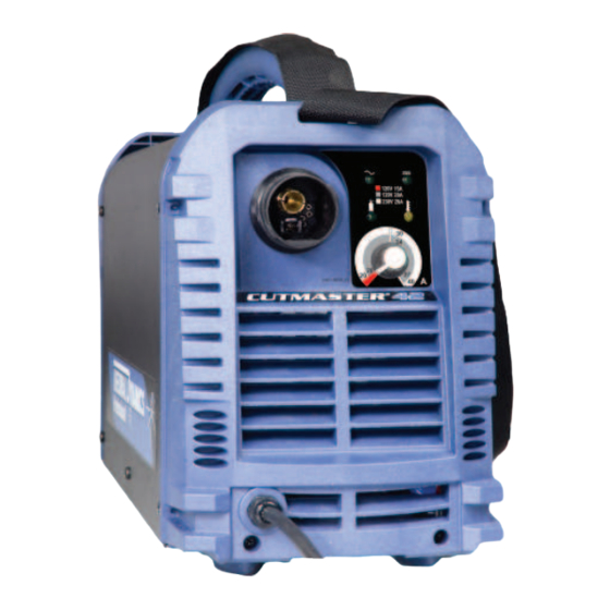
CUTMASTER 42 2.04 Power Supply Features 120/230 VAC Power Source Air Inlet Control Panel 120V 15A 120V 20A 230V 20A Art # A-09334_AC Torch Lead Work Cable and Clamp On/Off Switch Air Inlet Power Cord Art# A-09335 Manual 0-5141 INTRODUCTION... -
Page 18: Torch Specifications
Combination of ambient air and gas stream through torch. E. SL60 Torch Ratings (Refer to Note) NOTE Ratings shown apply to the SL60 Torch only. Refer to the Specifications chart on page 2T-1 for CutSkill 35A data. Plasma Power Supply Used With • Thermal Dynamics CutSkill 35A... -
Page 19: Section 2Torch: Introduction
CUTMASTER 42 SECTION 2TORCH: F. Torch Ratings INTRODUCTION SL40 Torch Ratings Ambient 104° F Temperature 40° C 2T.01 Scope of Manual Duty Cycle 100% @ 40 Amps @ 193 scfh This manual contains descriptions, operating instruc- Maximum Current 40 Amps tions and maintenance procedures for the SL40 Plasma Voltage (V 500V... -
Page 20: 03 Introduction To Plasma
CUTMASTER 42 2T.03 Introduction to Plasma B. Gas Distribution The single gas used is internally split into plasma and A. Plasma Gas Flow secondary gases. Plasma is a gas which has been heated to an extremely The plasma gas flows into the torch through the high temperature and ionized so that it becomes electri- negative lead, through the starter cartridge, around cally conductive. -
Page 21: Installation
CUTMASTER 42 SECTION 3: INSTALLATION 3.01 Unpacking 1. Use the packing lists to identify and account for each item. A. Contents List Description Quantity CM42 Power source 10ft power input cable (installed) 120VAC Adapter Pigtail 15A 120VAC Adapter Pigtail 20A Work cable and clamp (installed) SL40 Torch (15ft(4.6m)) w/consumables Carry case... -
Page 22: Primary Input Power Connections
CUTMASTER 42 3.03 Primary Input Power Connections Power Cords Included With Power Supply Attached to the power supply is an input power cord with a 230 Volt 50 Amp NEMA 6-50P for plug. Supplied adapters allow for connection of the power supply input cable plug for when using 120V input power. Art# A-09432_AB Figure 3-1 120VAC Adapter Pigtail CAUTION... -
Page 23: Air Supply Connections
CUTMASTER 42 3.04 Air Supply Connections A. Connecting Air Supply to Unit The connection is the same for compressed air or industrial compressed air in gas cylinders. 1. Connect the gas line to the compressed air inlet port at the appropriate pressure. On/Off Switch Air Inlet... - Page 24 This page left blank intentionally.
-
Page 25: Section 4 System: Operation
CUTMASTER 42 SECTION 4 SYSTEM: OPERATION 4.01 Control Panel On/Off Air Inlet Switch AC Indicator Power Cord DC Indicator (Ready) Air Indicator Overheat Indicator 120V 15A 120V 20A 230V 20A CUTMASTER ® Art# A-09338-AD The Front Panel The Rear Panel 1. -
Page 26: Preparations For Operating
CUTMASTER 42 Indicator is ON when DC output circuit is active. NOTE All consumables must be correctly installed and maintained to ensure correct operation. 4.02 Preparations For Operating At the start of each operating session: WARNING Disconnect primary power at the source before assembling or disassembling power supply, torch parts, or torch and leads assemblies. - Page 27 CUTMASTER 42 B. Torch Connection Check that the torch is properly connected. C. Check Primary Input Power Source 1. Check the power source for proper input voltage. Make sure the input power source meets the power require- ments for the unit per Section 2, Specifications. 2.
-
Page 28: Sequence Of Operation
CUTMASTER 42 G. Select Current Output Level Set the desired current output level. 120V 15A 120V 20A 230V 20A 27 7 4 4 0 27 7 4 4 0 120V, 15A 120V, 20A 230V, 20A A#09697_AA 4.03 Sequence of Operation The following is a typical sequence of operation for this power supply. - Page 29 CUTMASTER 42 NOTE Art # A-09342 For best performance and parts life, always use the correct parts for the type of operation. A. The torch can be comfortably held in one hand or steadied with two hands. Position the hand Trigger to press the Trigger on the torch handle.
-
Page 30: Cut Quality
CUTMASTER 42 B. The torch can be comfortably held in one hand 3. Complete cutting operation. or steadied with two hands. Position the hand NOTE to press the Trigger on the torch handle. With If the torch is lifted too far from the workpiece the hand torch, the hand may be positioned while cutting, the main arc will stop and the close to the torch head for maximum control... -
Page 31: General Cutting Information
CUTMASTER 42 Nitride Build - Up Nitride deposits can be left on the surface of the cut CAUTION when nitrogen is present in the plasma gas stream. Sparks from the cutting process can cause These buildups may create difficulties if the material damage to coated, painted, and other surfaces is to be welded after the cutting process. - Page 32 CUTMASTER 42 Dross When dross is present on carbon steel, it is com- monly referred to as either “high speed, slow speed, or top dross”. Dross present on top of the plate is normally caused by too great a torch to plate distance. "Top dross" is normally very easy to remove and can often be wiped off with a welding glove. "Slow speed dross"...
-
Page 33: Section 5 System: Service
CUTMASTER 42 SECTION 5 SYSTEM: SERVICE 5.01 General Maintenance Warning! There are extremely dangerous voltage and power levels present inside this product. Do not attempt to open or repair unless you are a qualified electrical tradesperson and you have had training in power measurements Maintain more often and troubleshooting techniques. -
Page 34: Basic Troubleshooting Guide
CUTMASTER 42 A. Every three months Check external air filter, replace if necessary. 1. Shut off input power; turn off the gas supply. Bleed down the gas supply. Check air filter and replace if neces- sary. NOTE Leave internal ground wire in place. B. Every six months 1. Check the in-line air filter(s), clean or replace as required. 2. - Page 35 CUTMASTER 42 3. Indicator blinking (3 sec ON/3 Sec OFF). Torch switch was depressed before machine was completely powered up. Turn ON/OFF switch to OFF position and the restart the machine by turning the power switch to ON. C. Air indicator 1.
- Page 36 CUTMASTER 42 2. Working cable connection to work piece is poor. Make sure that work cable has a proper connection to a clean, dry area of the work piece. 3. Faulty components in unit Return for repair or have qualified technician repair. H.
- Page 37 CUTMASTER 42 5. Torch parts worn Check torch shield cup, cutting tip, start cartridge and electrode. Replace as needed. 6. Faulty component in unit Return for repair or have qualified technician repair per service manual. L. Torch cuts but not well. 1.
- Page 38 This page left blank intentionally.
-
Page 39: Section 5 Torch: Service
CUTMASTER 42 SECTION 5 TORCH: Remove the consumable torch parts as follows: SERVICE NOTE The shield cup holds the tip and starter car- 5T.01 General Maintenance tridge shield cup in place. Position the torch with the shield cup facing upward to prevent NOTE these parts from falling out when the cup is removed. - Page 40 CUTMASTER 42 4. Remove the starter cartridge. Check for excessive SL40 Replacement Parts wear, plugged gas holes, or discoloration. Check Item # Description Cat. No the lower end fitting for free motion. Replace if Electrode 9-0096 necessary. Start Cartridge 9-0097 Tip, 20A Drag 9-0091 Tip, 40A Drag...
-
Page 41: Parts Lists
CUTMASTER 42 SECTION 6: PARTS LISTS 6.01 Introduction A. Parts List Breakdown The parts list provides a breakdown of all replaceable components. B. Returns If a product must be returned for service, contact your distributor. Materials returned without proper authorization will not be accepted. -
Page 42: Power Supply Replacement Parts
CUTMASTER 42 6.02 Power Supply Replacement Parts Item # Description Catalog # Logic PCB assembly 9-0076 Control PCB assembly 9-0077 Main PCB assembly 9-0079 Regulator 9-0081 Solenoid assembly 9-0082 Pressure Switch 9-0075 Front Panel with Label 9-0071 Rear Panel with Label 9-0072 Cover with Labels 9-0080... -
Page 43: Appendix 1: Circuit Diagram
CUTMASTER 42 APPENDIX 1: CIRCUIT DIAGRAM Art # A-09396_AE Manual 0-5141 APPENDIX... - Page 44 Notes...
- Page 45 This Page Intentionally Blank.
- Page 46 U.S. Customer Care: 800-426-1888 / 800-535-0557 Canada Customer Care: 905-827-4515 / 800-588-1714 • International Customer Care: 940-381-1212 / 940-483-8178 www.thermal-dynamics.com • A Global Cutting & Welding Market Leader ™ W O R L D H E A D Q U A R T E R S : 1 6 0 5 2 S w i n g l e y R i d g e R o a d , S u i t e 3 0 0 •...
Need help?
Do you have a question about the 42 CUTMASTER and is the answer not in the manual?
Questions and answers