
Related Manuals for Thermal Dynamics CutMaster 40MM


Summary of Contents for Thermal Dynamics CutMaster 40MM
- Page 1 380/400V CUTMASTER 40 mm ® PLASMA CUTTING SYSTEM Operating Manual Revision: AK Issue Date: February 17, 2014 Manual No.: 0-5084 VictorThermalDynamics.com...
- Page 2 WE APPRECIATE YOUR BUSINESS! Congratulations on your new Victor Thermal Dynamics product. We are proud to have you as our customer and will strive to provide you with the best service and reliability in the industry. This product is backed by our extensive warranty and world-wide service network. To locate your nearest distribu- tor or service agency call 1-800-426-1888, or visit us on the web at www.thermal-dynamics.com.
- Page 3 WARNING Read and understand this entire Manual and your employer’s safety practices before installing, operating, or servicing the equipment. While the information contained in this Manual represents the Manufacturer's best judgement, the Manufacturer assumes no liability for its use. Plasma Cutting Power Supply CutMaster 40mm ®...
-
Page 4: Table Of Contents
TABLE OF CONTENTS SECTION 1: GENERAL INFORMATION .....................1-1 1.01 Notes, Cautions and Warnings ..............1-1 1.02 Important Safety Precautions ..............1-1 1.03 Publications ....................1-2 1.04 Note, Attention et Avertissement ..............1-3 1.05 Precautions De Securite Importantes ............1-3 1.06 Documents De Reference ................1-6 1.07 Declaration of Conformity ................1-7 1.08 Statement of Warranty ................1-9... - Page 5 TABLE OF CONTENTS 4T.04 Hand Torch Operation ................4T-3 4T.05 Gouging ....................4T-6 4T.06 Mechanized Torch Operation ..............4T-7 4T.07 Parts Selection for SL100Torch Cutting ...........4T-8 4T.08 Recommended Cutting Speeds for SL100 Torch With Exposed Tip ..4T-10 4T.09 Recommended Cutting Speeds for SL100Torch With Shielded Tip ..4T-15 PATENT INFORMATION .....................4T-20 SECTION 5 SYSTEM: SERVICE .........................5-1...
- Page 6 This Page Intentionally Blank...
-
Page 7: General Information
CUTMASTER 40MM SECTION 1: To prevent possible injury, read, understand and follow all warnings, safety precautions GENERAL INFORMATION and instructions before using the equipment. Call 1-603-298-5711 or your local distributor if you have any questions. 1.01 Notes, Cautions and Warnings Throughout this manual, notes, cautions, and warnings are used to highlight important information. -
Page 8: Publications
CUTMASTER 40MM • Never touch any parts that are electrically “live” or “hot.” PLASMA ARC RAYS • Wear dry gloves and clothing. Insulate yourself from the work piece or other parts of the welding Plasma Arc Rays can injure your eyes and burn your circuit. -
Page 9: Note, Attention Et Avertissement
CUTMASTER 40MM 1.04 Note, Attention et Avertissement 4. ANSI Standard Z87.1, SAFE PRACTICES FOR OC- CUPATION AND EDUCATIONAL EYE AND FACE PROTECTION, obtainable from American National Dans ce manuel, les mots “note,” “attention,” et “aver- Standards Institute, 1430 Broadway, New York, NY tissement”... - Page 10 CUTMASTER 40MM Il faut communiquer aux opérateurs et au • Ce produit, dans le procéder de soudage et de coupe, personnel TOUS les dangers possibles. Afin produit de la fumée ou des gaz pouvant contenir des d’éviter les blessures possibles, lisez, compre- éléments reconnu dans L’état de la Californie, qui...
- Page 11 CUTMASTER 40MM Nuance Minimum Nuance Suggerée Courant Arc Protective Numéro Numéro INCENDIE ET EXPLOSION Moins de 300* Les incendies et les explosions peuvent résulter des 300 - 400* scories chaudes, des étincelles ou de l’arc de plasma. Le 400 - 800* procédé...
-
Page 12: Documents De Reference
CUTMASTER 40MM 1.06 Documents De Reference Consultez les normes suivantes ou les révisions les plus récentes ayant été faites à celles-ci pour de plus amples renseignements : 1. OSHA, NORMES DE SÉCURITÉ DU TRAVAIL ET DE PROTECTION DE LA SANTÉ, 29CFR 1910, disponible auprès du Superintendent of Documents, U.S. -
Page 13: Declaration Of Conformity
• 2004/108/EC The Electromagnetic Compatibility (EMC) Directive hereby declare that Equipment: Plasma Cutting Power Source Model Name/Number: CutMaster 40MM Market Release Date: January 20, 2012 is in conformity with the applicable requirements of the following harmonized standards • EN 60974-10:2007 Arc Welding Equipment - Part 10: Electromagnetic compatibility (EMC) requirements • EN 60974-1:2012 Arc Welding Equipment - Part 1: Welding power sources. - Page 14 CUTMASTER 40MM Classification: The equipment described in this manual is Class A and intended for industrial use. WARNING This Class A equipment is not intended for use in residential locations where the electrical power is provided by the public low-voltage supply system. There may be potential difficulties in ensuring electromagnetic compatibility in those locations, due to conducted as well as radiated disturbances.
-
Page 15: Statement Of Warranty
This warranty is exclusive and in lieu of any warranty of merchantability or fitness for a particular purpose. Victor Thermal Dynamics will repair or replace, at its discretion, any warranted parts or components that fail due to defects in material or workmanship within the time periods set out below. Victor Technologies, Inc. must be notified within 30 days of any failure, at which time Victor Technologies, Inc. - Page 16 CUTMASTER 40MM CIGWELD Terms of Warranty - 2014 Effective 1st January 2014, all warranties against defects (also known as a manufacturer’s warranty) supplied with goods or services must comply with the mandatory requirements in the new Australian Consumer Law and the Trade Practices (Australian Consumer Law) Amendment Regulations (2010) (No.1).
-
Page 17: Section 2 System: Introduction
Electronic copies of this manual can also be downloaded at no charge in Acrobat PDF format by going to the Victor Thermal Dynamics web site listed below and clicking on Victor Thermal Dynamics and then on the Literature link: http://www.victorthermaldynamics.com... -
Page 18: Power Supply Specifications
CUTMASTER 40MM 2.04 Power Supply Specifications CutMaster 40 Power Supply Specifications 380 VAC (360 - 440 VAC), Three Phase, 50/60 Hz Input Power 400 VAC (360 - 440 VAC), Three Phase, 50 Hz Input Power Cable Power Supply includes input cable. -
Page 19: Input Wiring Specifications
CUTMASTER 40MM 2.05 Input Wiring Specifications CutMaster 40 Power Supply Input Cable Wiring Requirements Input voltage Freq Power Input Suggested Sizes Fuse Flexible Cord Flexible Cord Volts I max I eff (amps) (Min. AWG) (Min. mm 3 Phase 23.6 Line Voltages with Suggested Circuit Protection and Wire Sizes... -
Page 20: Power Supply Features
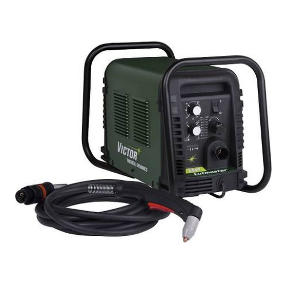
CUTMASTER 40MM 2.06 Power Supply Features Handle and Leads Wrap Control Panel Torch Leads Receptacle Art # A-08359 Work Cable and Clamp Port for Optional Automation Interface Cable Filter Assembly Gas Inlet Port Art # A-08547 Input Power Cord INTRODUCTION... -
Page 21: Section 2 Torch: Introduction
CUTMASTER 40MM SECTION 2 TORCH: 2T.03 Specifications INTRODUCTION A. Torch Configurations 1. Hand/Manual Torch, Models 2T.01 Scope of Manual The hand torch head is at 75° to the torch handle. The hand torches include a torch handle and torch This manual contains descriptions, operating instruc- trigger assembly. -
Page 22: 04 Options And Accessories
CUTMASTER 40MM E. Type Cooling H. Direct Contact Hazard Combination of ambient air and gas stream through For standoff tip the recommended standoff is 3/16 torch. inches / 4.7 mm. F. Torch Ratings 2T.04 Options And Accessories Manual Torch Ratings For options and accessories, see section 6. - Page 23 CUTMASTER 40MM By forcing the plasma gas and electric arc through a Torch Trigger small orifice, the torch delivers a high concentration Torch Switch To Control of heat to a small area. The stiff, constricted plasma Cable Wiring arc is shown in Zone C. Direct current (DC) straight...
- Page 24 CUTMASTER 40MM This Page Intentionally Blank 2T-4 INTRODUCTION Manual 0-5084...
-
Page 25: Section 3 System: Installation
CUTMASTER 40MM SECTION 3 SYSTEM: 3.03 Primary Input Power Connections INSTALLATION CAUTION 3.01 Unpacking Check your power source for correct voltage before plugging in or connecting the unit. 1. Use the packing lists to identify and account for The primary power source, fuse, and any each item. -
Page 26: Gas Connections
CUTMASTER 40MM Regulator/Filter Assembly CAUTION The primary power source and power cable Inlet Port must conform to local electrical code and the recommended circuit protection and wiring requirements (refer to table in Section 2). Hose Clamp 6. Connect the wires as follows. - Page 27 CUTMASTER 40MM Regulator/Filter Regulator/Filter Assembly Assembly 2-Stage Filter Inlet Port (IN) Regulator Input Outlet Port Inlet Port (OUT) Two Stage Filter Hose Clamp Assembly Gas Supply Hose Art # A-07944 1/4 NPT to 1/4” (6mm) Fitting Art # A-07945_AC Hose Clamp Optional Two - Stage Filter Installation 1/4 NPT to 1/4"...
- Page 28 CUTMASTER 40MM This Page Intentionally Blank INSTALLATION Manual 0-5084...
-
Page 29: Section 3 Torch: Installation
If necessary, connect the torch to the Power Supply. 2. Put the Function Control switch in the SET Connect only the Thermal Dynamics model SL100 / position. Manual or SL100 / Mechanical Torch to this power sup- ply. Maximum torch leads length is 100 feet / 30.5 m, 3. - Page 30 CUTMASTER 40MM Pinch Block Assembly Square Workpiece A-02585 Mechanical Torch Set - Up 3. The proper torch parts (shield cup, tip, start car- tridge, and electrode) must be installed for the type of operation. Refer to Section 4T.07, Torch Parts Selection for details.
-
Page 31: Section 4 System: Operation
CUTMASTER 40MM SECTION 4 SYSTEM: OPERATION 4.01 Front Panel Controls / Features See Illustration for numbering Identification 1. Output Current Control Sets the desired output current. Output settings up to 60 Amps may be used for drag cutting (with the torch tip contacting the workpiece) or higher for standoff cutting. -
Page 32: Preparations For Operation
Check that the torch is properly connected. Only ists and for a ten (10) minute period once the Thermal Dynamics model SL100 / Manual or SL100 condition is cleared. / Mechanical Torches may be connected to this Power Supply. - Page 33 LATCH position the main cutting arc will be main- tained after the torch switch is released. Art# A-07946 STANDOFF Typical Cutting Speeds CutMaster 40mm Gas Pressure Settings Cutting speeds vary according to torch output am- SL100 perage, the type of material being cut, and operator Leads...
- Page 34 CUTMASTER 40MM This Page Intentionally Blank OPERATION Manual 0-5084...
-
Page 35: Section 4 Torch: Operation
CUTMASTER 40MM SECTION 4 TORCH: 3. Install the replacement Electrode by pushing it straight into the torch head until it clicks. OPERATION 4 . Install the starter cartridge and desired tip for the operation into the torch head. 4T.01 Torch Parts Selection 5. -
Page 36: 03 General Cutting Information
CUTMASTER 40MM Bevel Angle Piloting The angle between the surface of the cut edge and Piloting is harder on parts life than actual cutting a plane perpendicular to the surface of the plate. because the pilot arc is directed from the electrode A perfectly perpendicular cut would result in a 0°... -
Page 37: 04 Hand Torch Operation
CUTMASTER 40MM dross" is normally very easy to remove and can Torch often be wiped off with a welding glove. "Slow speed dross" is normally present on the bottom edge of the plate. It can vary from a light to heavy bead, but does not adhere tightly to the cut edge, and can be easily scraped off. - Page 38 CUTMASTER 40MM Trigger WARNING The straight edge must be non - conductive. Trigger Release Non-Conductive Straight Edge Cutting Guide A-03539 Using Drag Shield Cup With Straight Edge Art # A-03383 6. Cut as usual. Simply release the trigger assembly The crown shield cup functions best when cutting to stop cutting.
- Page 39 CUTMASTER 40MM back end for maximum heat protection. Choose the technique that feels most comfortable and allows good control and movement. NOTE The tip should never come in contact with Trigger the workpiece except during drag cutting operations. Trigger Release 2.
-
Page 40: 05 Gouging
CUTMASTER 40MM Current Setting • Torch parts wear • Air quality Current settings depend on torch travel speed, mode of operation (hand or machine torch), and the • Line voltage fluctuations amount of material to be removed. • Torch standoff height •... -
Page 41: 06 Mechanized Torch Operation
CUTMASTER 40MM 4T.06 Mechanized Torch Operation For optimum smooth surface quality, the travel speed should be adjusted so that only the leading edge of the arc column produces the cut. If the travel Cutting With Mechanized Torch speed is too slow, a rough cut will be produced as... -
Page 42: 07 Parts Selection For Sl100Torch Cutting
CUTMASTER 40MM 4T.07 Parts Selection for SL100Torch Cutting Ohmic Clip Automation Torch Ohmic Clip 9-8224 Manual Torch 9-8259 20-40A Shield Tip: Shield Cap, Machine Cup Body, STANDOFF 40A 9-8245 9-8237 CUTTING 9-8205 Shield Cap, Deflector Shield Cup 9-8206 9-8243 9-8218... - Page 43 CUTMASTER 40MM This Page Intentionally Blank 4T-9 Manual 0-5084 OPERATION...
-
Page 44: 08 Recommended Cutting Speeds For Sl100 Torch With Exposed Tip
CUTMASTER 40MM 4T.08 Recommended Cutting Speeds for SL100 Torch With Exposed Tip Type Torch: SL100 With Exposed Tip Type Material: Mild Steel Type Plasma Gas: Air Type Secondary Gas: Single Gas Torch Thickness Output Amperage Speed (Per Minute) Standoff Plasma Gas Press... - Page 45 CUTMASTER 40MM Type Torch: SL100 With Exposed Tip Type Material: Mild Steel Type Plasma Gas: Air Type Secondary Gas: Single Gas Torch Thickness Output Amperage Speed (Per Minute) Standoff Plasma Gas Press Flow (CFH) Pierce Pierce Height Inches mm (Cat. No.) Volts(VDC)
- Page 46 CUTMASTER 40MM Type Torch: SL100 With Exposed Tip Type Material: Mild Steel Type Plasma Gas: Air Type Secondary Gas: Single Gas Torch Thickness Output Amperage Speed (Per Minute) Standoff Plasma Gas Press Flow (CFH) Pierce Pierce Height Inches mm (Cat. No.) Volts(VDC)
- Page 47 CUTMASTER 40MM Type Torch: SL100 With Exposed Tip Type Material: Mild Steel Type Plasma Gas: Air Type Secondary Gas: Single Gas Torch Thickness Output Amperage Speed (Per Minute) Standoff Plasma Gas Press Flow (CFH) Pierce Pierce Height Inches mm (Cat. No.) Volts(VDC)
- Page 48 CUTMASTER 40MM Type Torch: SL100 With Exposed Tip Type Material: Stainless Steel Type Plasma Gas: Air Type Secondary Gas: Single Gas Torch Thickness Output Amperage Speed (Per Minute) Standoff Plasma Gas Press Flow (CFH) Pierce Pierce Height Inches mm (Cat. No.) Volts(VDC)
-
Page 49: 09 Recommended Cutting Speeds For Sl100Torch With Shielded Tip
CUTMASTER 40MM 4T.09 Recommended Cutting Speeds for SL100Torch With Shielded Tip Type Torch: SL100 With Shielded Tip Type Material: Mild Steel Type Plasma Gas: Air Type Secondary Gas: Single Gas Torch Thickness Output Amperage Speed (Per Minute) Standoff Plasma Gas Press... - Page 50 CUTMASTER 40MM Type Torch: SL100 With Shielded Tip Type Material: Mild Steel Type Plasma Gas: Air Type Secondary Gas: Single Gas Torch Thickness Output Amperage Speed (Per Minute) Standoff Plasma Gas Press Flow (CFH) Pierce Pierce Height Inches mm (Cat. No.) Volts(VDC)
- Page 51 CUTMASTER 40MM Type Torch: SL100 With Shielded Tip Type Material: Mild Steel Type Plasma Gas: Air Type Secondary Gas: Single Gas Torch Thickness Output Amperage Speed (Per Minute) Standoff Plasma Gas Press Flow (CFH) Pierce Pierce Height Inches mm (Cat. No.)
- Page 52 CUTMASTER 40MM Type Torch: SL100 With Shielded Tip Type Material: Mild Steel Type Plasma Gas: Air Type Secondary Gas: Single Gas Torch Thickness Output Amperage Speed (Per Minute) Standoff Plasma Gas Press Flow (CFH) Pierce Pierce Height Inches (Cat. No.)
- Page 53 CUTMASTER 40MM Type Torch: SL100 With Shielded Tip Type Material: Stainless Steel Type Plasma Gas: Air Type Secondary Gas: Single Gas Torch Thickness Output Amperage Speed (Per Minute) Standoff Plasma Gas Press Flow (CFH) Pierce Pierce Height Inches mm (Cat. No.) Volts(VDC)
-
Page 54: Patent Information
CUTMASTER 40MM PATENT INFORMATION Plasma Cutting Torch Patents The following parts are covered under U.S. and Foreign Patents as follows: Catalog # Description Patent(s) 9-8215 Electrode US Pat No(s) 6163008; 6987238 Other Pat(s) Pending 9-8213 Cartridge US Pat No(s) 6903301; 6717096; 6936786;... - Page 55 CUTMASTER 40MM Catalog # Description Patent(s) 9-8245 Shield Cap US Pat No(s) 6914211; D496951 Other Pat(s) Pending The following parts are also licensed under U.S. Patent No. 5,120,930 and 5,132,512: Catalog # Description 9-8235 Shield Cap 9-8236 Shield Cap 9-8237...
- Page 56 CUTMASTER 40MM This Page Intentionally Blank 4T-22 OPERATION Manual 0-5084...
-
Page 57: Section 5 System: Service
CUTMASTER 40MM SECTION 5 SYSTEM: SERVICE 5.01 General Maintenance Maintain more often Warning! if used under severe Disconnect input power before maintaining. conditions Each Use Visual check of torch tip and electrode Weekly Visually inspect the cables and leads. Replace as needed... -
Page 58: Maintenance Schedule
3. Metal too thick. ing environment. 4. Worn torch parts 5. Cutting current too low. Daily Operational Checks or Every Six Cutting 6. Non - Genuine Thermal Dynamics Hours: parts used 7. Incorrect gas pressure 1. Check torch consumable parts, replace if dam- aged or worn. -
Page 59: Fault Indicator
CUTMASTER 40MM 5.04 Fault Indicator At initial power up, two lights will temporarily illumi- nate for 2-3 seconds to show the version of software used. To determine the first digit, count the function indicators left to right, 1 through 5. To determine the second digit count the pressure indicators, reading from bottom to top, 0 through 7. -
Page 60: Basic Troubleshooting Guide
CUTMASTER 40MM 5.05 Basic Troubleshooting Guide WARNING There are extremely dangerous voltage and power levels present inside this unit. Do not attempt to diagnose or repair unless you have had training in power electronics measurement and troubleshooting techniques. Problem - Symptom Possible Cause... - Page 61 CUTMASTER 40MM Problem - Symptom Possible Cause Recommended Action FAULT & 80 PSI 1. Torch shield cup is loose. 1. Tighten shield cup by hand. Do not overtighten. indicators flashing. 2. Torch tip, electrode or starter 2. Turn OFF power supply. Remove shield cup. Install missing Gas flow is cycling cartridge missing.
-
Page 62: Power Supply Basic Parts Replacement
CUTMASTER 40MM 5.06 Power Supply Basic Parts C. Filter Element Assembly Replacement Replacement The Filter Element Assembly is in the rear panel. For better system performance, the filter element should be checked per the Maintenance Schedule (Subsection 5.02), and either cleaned or replaced. - Page 63 CUTMASTER 40MM 6. Disconnect the input line from the filter element assembly. Housing 7. Remove the filter element assembly through the rear opening. NOTE Filter If replacing or cleaning just the filter element Element (Cat. No. 9-7741) refer to the following illustration for disas- sembly.
- Page 64 CUTMASTER 40MM 4. Note the location and orientation of the old Filter Elements. 5. Slide out the old Filter Elements. First & Second Stage Cartridges (as marked) Art # A-02942 Optional Two-Stage Filter Replacement 6. Slide the replacement Filter Elements into the Filter Assembly, with the same orientation as noted in Step 4 above.
-
Page 65: Section 5 Torch: Service
CUTMASTER 40MM SECTION 5 TORCH: SERVICE Upper Groove 5T.01 General Maintenance with Vent Holes Must Remain Open NOTE Refer to Previous "Section 5 System" for com- Upper O-Ring in Correct Groove mon and fault indicator descriptions. Threads Cleaning Torch Lower O-Ring... -
Page 66: 02 Inspection And Replacement Of Consumable Torch Parts
CUTMASTER 40MM 5T.02 Inspection and Replacement of 4. Remove the tip. Check for excessive wear (indi- cated by an elongated or oversized orifice). Clean Consumable Torch Parts or replace the tip if necessary. Good Tip Worn Tip WARNING Disconnect primary power to the system before disassembling the torch or torch leads. -
Page 67: Parts Lists
The following items are included with the replacement power supply: work cable & clamp, input power cable, gas pressure regulator / filter, and operating manual. Description Catalog # CutMaster 40mm Non CE Power Supply with 400VAC, 3 phase input power cable 3-1930-3 CutMaster 40mm CE Power Supply... -
Page 68: Options And Accessories
CUTMASTER 40MM 6.05 Options and Accessories Description Catalog # Single - Stage Filter Kit (includes Filter & Hose) 7-7507 Replacement Filter Body 9-7740 Replacement Filter Hose (not shown) 9-7742 Replacement Filter Element 9-7741 Two - Stage Filter Kit (includes Hose & Mounting Screws) - Page 69 CUTMASTER 40MM Art # A-07993_AB Manual 0-5084 PARTS LIST...
-
Page 70: Replacement Parts - For Machine Torches With Unshielded Leads
CUTMASTER 40MM 6.07 Replacement Parts - for Machine Torches with Unshielded Leads Item No. Qty Description Catalog No. Torch Head Assembly without leads (includes items 2, 3, and 14) 9-8220 Large O-Ring 8-3487 Small O-Ring 8-3486 PIP Switch Kit 9-7036 Unshielded Automated Leads Assemblies with ATC connectors 5 - foot / 1.5 m Leads Assembly with ATC connector... - Page 71 CUTMASTER 40MM 5 & 6 A-07994_AB Manual 0-5084 PARTS LIST...
-
Page 72: Replacement Shielded Machine Torch Leads Assemblies
CUTMASTER 40MM 6.08 Replacement Shielded Machine Torch Leads Assemblies Item No. Qty Description Catalog No. Mechanized Shielded Leads Assemblies with ATC Connectors 5 - foot / 1.5 m Leads Assembly with ATC Connector 4-7846 10 - foot / 3.05 m Leads Assembly with ATC Connector 4-7847 25 - foot / 7.6 m Leads Assembly with ATC Connector... -
Page 73: Torch Consumable Parts (Sl100)
CUTMASTER 40MM 6.09 Torch Consumable Parts (SL100) Ohmic Clip Automation Torch Ohmic Clip 9-8224 Manual Torch 9-8259 20-40A Shield Tip: Shield Cap, Machine Cup Body, STANDOFF 9-8237 40A 9-8245 CUTTING 9-8205 Shield Cap, Deflector Shield Cup 9-8206 9-8243 9-8218 9-8208... - Page 74 CUTMASTER 40MM This Page Intentionally Blank PARTS LIST Manual 0-5084...
-
Page 75: Appendix 1: Sequence Of Operation (Block Diagram
CUTMASTER 40MM APPENDIX 1: SEQUENCE OF OPERATION (BLOCK DIAGRAM) ACTION: ACTION: ACTION: ACTION: RUN / Rapid Auto Restart / ON / OFF switch to ON Close external RUN / SET / LATCH disconnect switch. Rapid Auto Restart / switch to RUN... -
Page 76: Appendix 2: Data Tag Information
CUTMASTER 40MM APPENDIX 2: DATA TAG INFORMATION West Lebanon, NH USA 03784 Manufacturer's Name and/or Logo, Location, Model and M odel : Revision Level, Serial Number and Production Code Dat e of M f r : Made in USA Type of Power... -
Page 77: Appendix 3: Torch Pin - Out Diagrams
CUTMASTER 40MM APPENDIX 3: TORCH PIN - OUT DIAGRAMS A. Hand Torch Pin - Out Diagram ATC Female Receptacle ATC Male Connector Front View Front View Negative / Negative / Plasma Plasma 8 - Open 8 - Ground 4 - Green /... -
Page 78: Appendix 4: Torch Connection Diagrams
CUTMASTER 40MM APPENDIX 4: TORCH CONNECTION DIAGRAMS A. Hand Torch Connection Diagram Torch: SL60 / SL100 Hand Torch Leads: Torch Leads with ATC Connector Power Supply: with ATC Receptacle Male ATC Leads ATC Female Receptacle Power Connector Torch Torch Supply... - Page 79 CUTMASTER 40MM This Page Intentionally Blank Manual 0-5084 APPENDIX...
-
Page 80: Appendix 5: System Schematic, 400V Units
CUTMASTER 40MM APPENDIX 5: SYSTEM SCHEMATIC, 400V UNITS PRI 3 PRI 3 PRI 4 PRI 4 BIAS SUPPLY PRI 2 PRI 2 PRI 2 PRI 2 INRUSH +12VDC PRI 1 PRI 1 RESISTORS PRI 1 PRI 1 MTH1 MTH1 MTH2... - Page 81 ECO B1611 05/05/09 Date: Date: Date: Information Proprietary to THERMAL DYNAMICS CORPORATION. Information Proprietary to THERMAL DYNAMICS CORPORATION. Information Proprietary to THERMAL DYNAMICS CORPORATION. MARCH 30, 2009 Not For Release, Reproduction, or Distribution without Written Consent. Not For Release, Reproduction, or Distribution without Written Consent.
-
Page 82: Appendix 6: Publication History
CUTMASTER 40MM APPENDIX 6: Publication History Cover Date Rev. Change(s) Sept. 19, 2008 AA Manual released. May 28, 2009 AB Updated 400V/600V schematic in appendix per ECOB1399. Corrected part numbers in section 6 per ECOB1201. Jan. 7, 2010 Updated “Power Supply Input Cable Wiring Requirements” with metric cable sizes in Section 2. - Page 83 This Page Intentionally Blank...
- Page 84 THE AMERICAS Denton, TX USA U.S. Customer Care Ph 1-800-426-1888 (tollfree) Fax: 1-800-535-0557 (tollfree) International Customer Care Ph 1-940-381-1212 Fax: 1-940-483-8178 Miami, FL USA Sales Office, Latin America Ph 1-954-727-8371 Fax: 1-954-727-8376 Oakville, Ontario, Canada Canada Customer Care Ph 1-905-827-4515 Fax: 1-800-588-1714 (tollfree) EUROPE Chorley, United Kingdom...
Need help?
Do you have a question about the CutMaster 40MM and is the answer not in the manual?
Questions and answers