Advertisement
Quick Links
cover
5/11/95 9:42 AM
Page 1
© Samsung Electronics Co.,Ltd. MAR. 1999
Printed in Korea
AD68-00079B
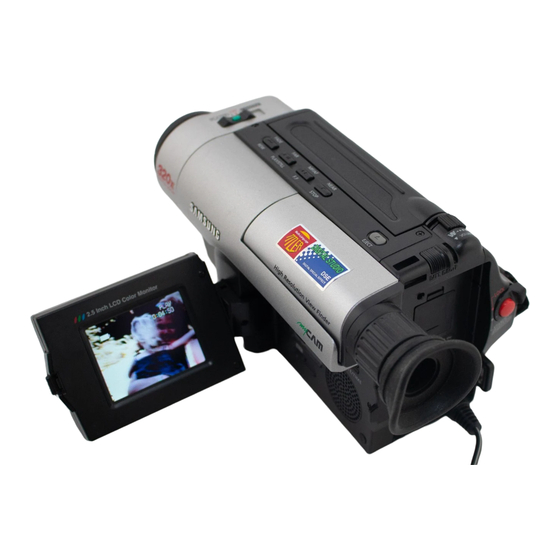
8mm CAMCORDER
SCL300/L310/L320/L330/L350
SCL800/L850
VP-L300/L320/L330/L350
VP-L980
SERVICE
For mechanical disassembly and adjustment, refer to the "Mechanical Manual"
(DE-6
AD68-30200A).
8mm CAMCORDER
Manua
CONTENTS
1. Precautions
2. Service Tips
3. Product Specifications and
Comparison Chart
4. Disassembly and Reassem
5. Alignment and Adjustment
6. Exploded View and Parts L
7. Electrical Parts List
8. PCB Diagrams
9. Wiring Diagram
10. Schematic Diagrams
Advertisement

Related Manuals for Samsung SCL300


Summary of Contents for Samsung SCL300
- Page 1 3. Product Specifications and Comparison Chart 4. Disassembly and Reassem 5. Alignment and Adjustment 6. Exploded View and Parts L 7. Electrical Parts List 8. PCB Diagrams 9. Wiring Diagram © Samsung Electronics Co.,Ltd. MAR. 1999 Printed in Korea AD68-00079B 10. Schematic Diagrams...
- Page 2 Alternatively, wear a dis- charging Wrist-strap device. (Be sure to tion, replace the picture tube only with one that is the same type as the original. remove it prior to applying power--this is an electric shock precaution.) Samsung Electronics...
- Page 3 16. Always connect a test instrument’s ground might create shock, fire or other hazards. lead to the instrument chassis ground before connecting the positive lead; always remove the instrument’s ground lead last. Samsung Electronics...
- Page 4 5. Reassemble the video light cover unit to the cam- corder carefully as figure. Do not apply excessive force because the cover is easy to be broken. 6. Reassemble the screw with a small screw driver to the camcorder. Samsung Electronics...
- Page 5 Service Tips MEMO MEMO Samsung Electronics...
- Page 6 Built-in speaker Dynamic, 0.5 W standard Operating temperature 0°C to 40°C (32°F to 104°F) Dimension (WXHXD) SCL300/L310/L320/L330 : 109X104X215 mm (4.29X4.09X8.46 inch) SCL350/L800/L850 : 109X104.5X221mm (4.29X4.09X8.7 inch) Weight SCL300/L310/L320 : 860 g (1.89 lbs), SCL330 : 870 g (1.92 lbs) SCL350 : 900 g (1.98 lbs),...
- Page 7 0°C to 40°C (32°F to 104°F) Dimension (WXHXD) VP-L300/L320/L330 : 109X104X215, VP-L350/L980 : 109X104.5X221 Weight VP-L300/L320 : 860 g, VP-L330 : 870 g VP-L350 : 900 g, VP-L980 : 900 g The technical specifications and design may be changed without notice. Samsung Electronics...
- Page 8 Product specifications and comparison chart 3-3 Comparison Chart Model NTSC SCL300 SCL310 SCL320 SCL330 SCL350 SCL800 SCL850 Features Format 8 mm 8 mm 8 mm 8 mm 8 mm Hi8 mm Hi8 mm LCD Size 2.5´´ 2.5´´ 2.5´´ 3´´ 3´´...
- Page 9 Product specifications and comparison chart MEMO MEMO Samsung Electronics...
-
Page 10: Disassembly And Reassembly
You don’t need to disassemble the Cover Housing except that you change the Deck Remove 2 screws. Mechanism. Remove the ass'y cover housing in the direction of arrow Fig. 4-1 Ass’y Cover Housing Removal Samsung Electronics... - Page 11 REASSEMBLY : Put the 7 tabs into the slot, while sliding it as shown in DETAIL "B". 2 locking tabs "B" Precision screw driver < DETAIL "B" > < DETAIL "A" > Fig. 4-2 Ass’y Case Top Removal Samsung Electronics...
- Page 12 (Ass'y front for Pull out the ass'y front in Non-EIS models) the direction of arrow Remove 4 screws. Disconnect the FPC or wire from the audio block of MAIN PCB. (Ass'y front for EIS models) Fig. 4-3 Ass’y Front Removal Samsung Electronics...
- Page 13 Disassemblr and Reassembly 4-1-4 Ass’y Case Right Removal Pull out the unit case in the direction of arrow Remove 4 screws. Disassemble after turning knob to be "LOCK". Fig. 4-4 Ass’y Case Right Removal Samsung Electronics...
- Page 14 Disassemblr and Reassembly 4-1-5 Ass’y Case Left Removal Pull out the case left assembly in the direction Disconnect wire of arrow of 15 pins. Disconnect wire of 10 pins. Remove 5 screws. Fig. 4-5 Ass’y Case Left Removal Samsung Electronics...
- Page 15 Disassemblr and Reassembly 4-1-6 Ass’y LCD Removal Remove 1 screw. Remove 2 screws. Pull out the LCD assembly in the direction of arrow Pull out the cover in the direction of arrow Fig. 4-6 Ass’y LCD Removal Samsung Electronics...
- Page 16 Disassemblr and Reassembly 4-1-7 Ass’y EVF Removal Remove 2 screws. Remove 1 screw. Disconnect wire of 3 pins from the FUNCTION PCB. Pull out the EVF ass'y in the direction of arrow Fig. 4-7 Ass’y EVF Removal Samsung Electronics...
- Page 17 Disassemblr and Reassembly 4-1-8 Ass’y Rear Board Removal Remove 1 screw. Pull out the ass'y REAR board in the direction of arrow Remove 1 screw. Fig. 4-8 Ass’y Case Rear Removal Samsung Electronics...
- Page 18 4-1-9 Ass’y 8mm Deck Removal Remove 3 screws. Disconnect connector from the MAIN PCB. Disconnect connector from the Head-Drum. Pull out the MAIN PCB from the ass'y DECK in the directiob of arrow Fig. 4-9 Ass’y 8mm Deck Removal Samsung Electronics...
- Page 19 Remove solder with an iron to isolate PCB and LENS. Disconnect connector and pull out the ass'y LENS in the direction of arrow Disconnect FPC from the connector of the MAIN PCB. Fig. 4-10 Ass’y Camera Removal 4-10 Samsung Electronics...
-
Page 20: Circuit Boards Location
4-2 Circuit Boards Location ASS'Y EIS BOARD (EIS MODEL) ASS'Y FRONT BOARD (NON EIS MODEL) ASS'Y CCD BOARD ASS'Y MAIN BOARD ASS'Y EVF BOARD ASS'Y REAR BOARD ASS'Y LCD BOARD ASS'Y FUNCTION BOARD Fig. 4-11 Circuit Boards Location Samsung Electronics 4-11... - Page 21 MIC ASS’Y –– CN893 FRONT PCB MIC ASS’Y –– CN893 FRONT PCB MIC ASS’Y –– CN895 FRONT PCB LIGHT ASS’Y –– CN472 FUNCTION PCB –– CN473 FUNCTION PCB SPEAKER –– –– HINGE –– Fig. 4-12 Connector Diagrams 4-12 Samsung Electronics...
- Page 22 Test Points for Mechanism Alignment 1. PB RF - Pin 11 of CN605 2. Head Switching (Trigger) - Pin 9 of CN605 PB RF Head Switching - Trigger CN605 Fig. 1 Test point Fig. 2 Test location of test point Samsung Electronics...
- Page 23 COMMON GROUND IC601 28PIN IC601 27PIN IC601 26PIN LOADING EJECT UNLOADING PLAY LOADING STOP STOP IC601 IC601 IC601 POSITION ACTION MODE 28PIN 27PIN 26PIN EJECT EJECT UNLOADING STOP UNLOADING STOP LOADING STOP LOADING STOP PLAY, FF, Z/RTN, STILL..Samsung Electronics...
-
Page 24: Camera Section Adjustment
Data store after finishing adjustment by DATA UP/DOWN button. EDIT – (DATA DOWN) When change data value of adjust state. EDIT + (DATA UP) TITLE (MODE UP) Mode change. DATE/TIME (MODE DOWN) Manual focus adjustment. (FAR/NEAR) ZOOM TELE/ZOOM WIDE Move the zoom position of lens. Samsung Electronics... - Page 25 Then unit goes into service mode. STEP 3 On screen display show “ODF. T.INI XX XX” CAM- ERA ADJUSTMENT mode has successfully been activated. Note : When ÒXX XXÓ is shown in service adjustment procedures, this indicates variable values. Samsung Electronics...
-
Page 26: Samsung Electronics
"@CDS E-R(e1,e0),J-R(j0),M-R;D0:e0,D1:e1,D2:j0(CAM),D4:e0,D5:e1,D6:j0(VCR),D7:cds-rev='1'" "@CDS F-REG(f9,f2) VCR ;PGA GAIN -HIGH(0.00dB~ 10.0dB)" @WDR REGISTER[7,0] *AEINSEL=D7,AELPFSEL=D6,X[5:0] @WDR REGISTER[15,8] *AECLIP_TH[7:0] @WDR REGISTER[23,16] *AEL_TH[7:0] @WDR REGISTER[31,24] *AEH_TH[7:0] @WDR REGISTER[39,32] *AEW2VE[7:0] @WDR REGISTER[47,40] *AEW2VS[7:0] @WDR REGISTER[55,48] *AEW2HE[7:0] @WDR REGISTER[63,56] *AEW2HS[7:0] @WDR REGISTER[71,64] *AEW1VE[7:0] @WDR REGISTER[79,72] *AEW1VS[7:0] Samsung Electronics... - Page 27 AUTO 3MLENS ADJ(0DE) ZOOM PULSE LOW 16X LENS changed by AUTO 3MLENS ADJ(0DE) ZOOM PULSE HIGH 16X LENS changed by AUTO AWB ADJ(0CF) R-CONTROL 3100K changed by AUTO AWB ADJ(0CF) B CONTROL 3100K changed by AUTO AWB ADJ(0CF) R-CONTROL 5100K Samsung Electronics...
- Page 28 "@WDR ON; ADDR#136;GREEN DARK SLICE" @CINEMA F-ZONE LIMIT UP @CINEMA F-ZONE LIMIT UP @R-GAIN POSITIVE(ADDR.147) at OUTDOOR @R-GAIN NEGATIVE(ADDR.148) at OUTDOOR @R-HUE POSITIVE (ADDR.149) at OUTDOOR @R-HUE NEGATIVE (ADDR.14A) at OUTDOOR @B-GAIN POSITIVE(ADDR.14B) at OUTDOOR @B-GAIN NEGATIVE(ADDR.14C) at OUTDOOR Samsung Electronics...
- Page 29 "@D/ZOOM MAX RATIO; CO=4X, EE=14.3X, F4= 20X " @ NOISE SLICE START AGC VALUE @ HAP(DSP #10BH) MIN VALUE AT AGC MAX @ VAP(DSP 310C) MIN VALUE AT AGC MAX @ YAP(DSP #10DH) MAX VALUE AT AGC MAX @ CHROMA SUPPRESS PERCENT Samsung Electronics...
- Page 30 @HALL CLOSE TARGET NO USED EIS GYRO-RESET TIME '0C=3.7SEC' EIS START TIME ('10'=4.4SEC) AFTER EIS GYRO-RESET @IRIS CONTROL OF ZOOM WIDE POSITION AT LENS ADJUSTMENT @QB_GCTRL @AETAR L (FLEX-ZONE) @AETAR H (FLEX-ZONE) @@HALL AUTO ADJUST @@IRIS AUTO ADJUST Samsung Electronics...
- Page 31 @@AGC AUTO ADJUST (ADDR. 0B0,0B1,0D1,0AC,0AD) "@LENS ZOOM TRACK CHECKING ;CONFIRM,DATA UP,DOWN KEY" NO USED "@@LENS 3M ZOOM TRACK ADJUST =SERVICE FIELD MODE (KEEP DISTANCE; 3M+/-1Cm)" @EEPROM -TABLE -INITIAL ('99'+CONFIRM =CAMERA ONLY, 'AA'+CONFIRM=CAM+VCR INITIAL) ~0FF ~0FF ~0FF ~0FF VCR ADDRESS & DATA 5-10 Samsung Electronics...
- Page 32 |---- RAM-OUT[7:0] ----| |---- PFINDCNT[5:0] ----| * AWB- AREA INTERVAL FORM CENTER AXIS LENS HYSTERESIS ZOOM TRACKING CURVE CLUSTER 2 (HEADER[3:0] = 4'b0010) LUMINANCE "YVBKTH[1;0]" YVBKG[1:0] "YHBKTH[1;0]" YHBKG[1:0] Y_H_GAIN[1:0] |---- Y_H_POSI_GAIN[4:0] ----| Y_L_GAIN[1:0] YOLD-GAMMA |---- Y_V_POSI_GAIN[4:0] ----| Samsung Electronics 5-11...
- Page 33 |---- CBRG[7:0] R-G signal coeff. for B-Y signal creating. ----| |---- CRBG[7:0] B-G signal coeff. for R-Y signal creating. ----| |---- CBBG[7:0] B-G signal coeff. for B-Y signal creating. ----| |---- CRYGP[7:0] R-Y GAIN CONTROL + ----| 5-12 Samsung Electronics...
- Page 34 VZOFFE[7:0] EVEN FIELD LINE OFFSET ----| |---- VZOFFO[7:0] ODD FIELD LINE OFFSET ----| |---- HZOOM[7:0] ----| MOSAIC H-ADJ[1:0] HZSTR[8] |---- HZSTR[7:0] ----| |---- HZOFS[7:0] ----| |---- MOSAIC[5:0] 4d=8x8,5d=10x10,63d=126x126 ----| MOSAIC V-ADJ[1:0] FE MODE[1:0] 01=F,10=H.M FCM[9:8] |---- FCM[7:0] ----| HMIRROR[9:8] Samsung Electronics 5-13...
- Page 35 OAF_CLIP_TH[7:0] AF CLIP COUNTER THRESHOLD ----| |---- OAE_CLIP_TH[7:0] AE CLIP COUNTER THRESHOLD ----| OVAF OLPFSEL OFILPASS OYISEL OAWBSEL |---- OZNSEL[2:0] ----| ODMTST OAWBC SEL ORBSEL OAWB AREA DUMMY DUMMY DUMMY DUMMY CLUSTER 9 (HEADER[3:0]=4'b1001 ,AWB |---- ORYTH[4:0] ----| 5-14 Samsung Electronics...
- Page 36 CLUSTER 11 (HEADER[3:0] = 4'b1011) ,AF DATA2 * AF ZIGZAG NOISE THRESHOLD1 ----| * AF ZIGZAG CHECKING TIME1 ----| * AF ZIGZAG NOISE THRESHOLD2 ----| * AF ZIGZAG CHECKING TIME2 ----| * AF ZIGZAG NOISE THRESHOLD3 ----| * AF PEAK CONFIRM THRESHOLD1 ----| Samsung Electronics 5-15...
- Page 37 * AWB HALL STOP AT SPORTS MODE ----| * AWB HALL AT PORTRAIT MODE * AWB HALL AT SAND&SNOW MODE "CLUSTER 13 (HEADER[3:0] = 4'b1101); DECODER 1" ~1FC ~1FC ~1FC ~1FC FIXED ----| ~1FF ~1FF ~1FF ~1FF MICOM VERSION 5-16 Samsung Electronics...
- Page 38 Alignment and Adjustment CHANGED DATA BY MODEL ADDR DATA CONTENT APPLY MODEL NTSC NORMAL NORMAL BIT SEGMENTATION EXPLAIN * OPTION SELECT( WDR ,M/FOCUS RING,REMOCON) VP-L300/SCL300 SCL310/SCL320 * GLOBAL DELAY Samsung Electronics 5-17...
- Page 39 The adjustment is finished when the O.K! message appears on the TV screen. At the wide zoom position, the brightness of picture depends on data of Addr. 0C9, if the picture is dark, decrease the data of Addr. 0C9. (3M±1cm) (Be sure to maintain the distance.) LENS 5-18 Samsung Electronics...
- Page 40 5) Adjust the ÒEDIT + (DATA UP)/EDIT Ð (DATA DOWN)Ó button and MENU/ENTER(CONFIRM) but- ton so that frequency is : VP-L300/320/330 --> 9.453125MHz ± 50Hz. VP-L350/980 --> 14.18750MHz ± 50Hz. NTSC : SCL300/310/320/330/350 --> 9.534964MHz ± 50Hz. SCL800/850 --> 14.318182MHz ± 50Hz. P.CLK ADJUSTMENT X-TAL...
- Page 41 R-Y axial on screen of the vectorscope. b. W/B Outdoor Note : Bright dot shifts after the confirm button is b-1. Aim the camera at a 5100¡K gray-scale (or, pressed. 3100¡K+C16 filter) chart illuminated at 1500 to 2000 lx. (40us) 5-20 Samsung Electronics...
- Page 42 7) Be sure to press the ÒMENU/ENTER(CON- FIRM)Ó button to memorize setting. FIRM)Ó button to memorize setting. Note : Bright dot shifts after the confirm button is Note : Bright dot shifts after the confirm button is pressed. pressed. 70IRE 50IRE Samsung Electronics 5-21...
- Page 43 DOWN)Ó button so that the yellow vector is BLUE VECTOR 165. 346 DEG. 7) Be sure to press the ÒMENU/ENTER (CON- FIRM)Ó button to memorize setting. Note : Bright dot shifts after the confirm button is pressed. 5-22 Samsung Electronics...
- Page 44 FIRM)Ó button to memorize setting. FIRM)Ó button to memorize setting. Note : Bright dot shifts after the confirm button is Note : Bright dot shifts after the confirm button is pressed. pressed. RED VECTOR 104 DEG. CYAN VECTOR 284 DEG. Samsung Electronics 5-23...
- Page 45 1) CAMERA ÒAUTOÓ, Aim the gray scale chart. 2) Viewfinder and VRE03. 3) Adjust VRE03 so that all steps of the gray scale can be distinguished. 2. V. Size 3. Bright 1. AFC VRE02 VRE03 V.SIZE BRIGHT ICE01 VRE01 EVF PCB (Solder side) 5-24 Samsung Electronics...
- Page 46 On screen display shows "A VCO EPR:XX EVR : XX EVR:XX" LCD adjustment mode has suc- cessfully been activated. Note : "XX XX" indicates variable value. CAMERA/VIDEO PLAY/STILL STOP EJECT SELECT SWITCH BUTTON BUTTON BUTTON BUTTON BUTTON Samsung Electronics 5-25...
- Page 47 COLOR MAX 04 (02) 04 (02) COLOR MAX FIXED TINT MIN 06 (00) 06 (00) TINT MIN FIXED TINT MAX 04 (00) 04 (00) TINT MAX FIXED CHECK 1 CHECK 1 FIXED CHECK 2 CHECK 2 FIXED 5-26 Samsung Electronics...
- Page 48 4) By using "TITLE" button of unit, change the adjustment address to 05 Bright EPR:XX LVR:XX. 5) By using "EDIT +/Ð" button of unit, adjust the voltage VCOM 6.5V ± 0.1 Vp-p. 6) Confirm with " MENU" button of unit. 1VDC 20uS 6.5 Vp-p Samsung Electronics 5-27...
- Page 49 20uS level. 6) Confirm with "MENU" button of unit. 1VDC 20uS RED : CARRIER LEVEL : MINIMUM 4. TINT (SCL300/L350 only) PEDESTAL YELLOW LEVEL LEVEL 1) Color bar pattern 2) TP B and EVR 3) Connect the probe of oscilloscope to TP-B.
- Page 50 VCR UNREG JIG SCK FRONT PCB SS GND MAIN PCB JIG SO JIG DETECT JIG SI Press the SW772 (START/STOP) SW772 button to record in the VCR adjustment mode. REAR PCB FUNCTION PCB Fig. 1 Video Signal Connection Samsung Electronics 5-29...
- Page 51 Address of the adjustment mode. EPR:XX EVR:XX Name of the adjustment mode. : there are 01 to 1C.(refer 5-32) : every address have a name like this (refer 5-32) Present data New data : be adjusted before. : be adjusted newly. 5-30 Samsung Electronics...
- Page 52 5. If you want to finish the adjustment mode, you have to do Battery Reset. The Battery Reset means that you pull out the power source and pull in it again. Then, the adjustment ended and the camcorder works normally. Samsung Electronics 5-31...
- Page 53 Y-FM CARRIER (HI8) — Adjustment WHITE CLIP (HI8) — MTFQ (HI8) — D CLIP (HI8) — MODEL CODE Model code setting Model code setting Y-EMPHASIS IN (HI8) — Adjustment Y-FM DEVIATE (HI8) — Adjustment COLOR BAR LEVEL Adjustment Adjustment 5-32 Samsung Electronics...
- Page 54 XXÓ ÒXXÓ is different dependent on the model the PLAY button. as below. MODEL NAME ADDRESSED CODE MODEL NAME ADDRESSED CODE SCL300 VP-L300 Note : If there is no video out, when you pressed SCL310 VP-L320 the PLAY button, you can not adjust the SCL320 VP-L330 Head Switching Point.
- Page 55 Reset the power source so as to fix the new data h. Be sure to press the ÒMENU/ENTER(CON- to the EEPROM. FIRM)Ó button of CAMCORDER to memorize setting. i. Reset the power source so as to fix the new data to the EEPROM. 5-34 Samsung Electronics...
- Page 56 JIG DETECT JIG SI g. Press the ÒEDIT + (DATA UP)/EDIT Ð (DATA DOWN)Ó button so that the CN605 PIN13 is 1.0±0.02Vp-p from SYNC to peak level. WHITE ( APPROX. 100% ) APPROX. 0.02Vp-p 0.7V APPROX. 0.3V Samsung Electronics 5-35...
- Page 57 Connect the oscilloscope to the addressed Test Point. AUDIO OUT R VIDEO OUT AUDIO OUT R PB RF AUDIO OUT L HD SW VCR UNREG JIG CS VCR UNREG JIG SCK SS GND JIG SO JIG DETECT JIG SI 5-36 Samsung Electronics...
- Page 58 EEPROM. 0.5 0.02Vp-p h. Be sure to press the ÒMENU/ENTER(CON- FIRM)Ó button of CAMCORDER to memorize setting. i. Reset the power source so as to fix the new data to the camcorderÕs EEPROM. Samsung Electronics 5-37...
- Page 59 WHITE ( APPROX. 100% ) APPROX. 0.7V 1.0 0.02Vp-p APPROX. 0.3V h. Be sure to press the ÒMENU/ENTER(CONFIRM)Ó button of CAMCORDER to memorize setting. i. Reset the power source so as to fix the new data to the camcorderÕs EEPROM. 5-38 Samsung Electronics...
- Page 60 JIG SO JIG DETECT JIG SI h. Record for enough time to check the waveform when you playback where you recorded in step f). * 1 minute may be enough to check the wave- form in playback mode. Samsung Electronics 5-39...
- Page 61 Connect the oscilloscope to the addressed Test Point. AUDIO OUT R VIDEO OUT AUDIO OUT R PB RF AUDIO OUT L HD SW VCR UNREG JIG CS VCR UNREG JIG SCK SS GND JIG SO JIG DETECT JIG SI 5-40 Samsung Electronics...
- Page 62 Connect the oscilloscope to the addressed Test Point. AUDIO OUT R VIDEO OUT AUDIO OUT R PB RF AUDIO OUT L HD SW VCR UNREG JIG CS VCR UNREG JIG SCK SS GND JIG SO JIG DETECT JIG SI Samsung Electronics 5-41...
- Page 63 Connect the oscilloscope to the addressed Test Point. AUDIO OUT R VIDEO OUT AUDIO OUT R PB RF AUDIO OUT L HD SW VCR UNREG JIG CS VCR UNREG JIG SCK SS GND JIG SO JIG DETECT JIG SI 5-42 Samsung Electronics...
- Page 64 6-1 Cabinet Assembly (1) 6-2 Cabinet Assembly (2) 6-3 Cabinet Assembly (3) 6-4 Cabinet Assembly (4) 6-5 Cabinet Assembly (5) 6-10 6-6 EVF 6-12 6-7 Mechanical Parts (1) 6-14 6-8 Mechanical Parts (2) 6-16 6-9 Mechanical Parts (3) 6-18 Samsung Electronics...
- Page 65 Exploded View and Parts List 6-1 Cabinet Assembly (1) CN451 Samsung Electronics...
- Page 66 Exploded View and Parts List Loc. No New Part No Description and Specification Remark AD64-30995A CASE-LEFT;-,ABS94,HB,-,-,-,VP-L300,- SCL300/SCL310/SCL320/VP-L300 AD64-30995B CASE--LEFT;-,ABS94HB,-,-,-,D/GRAY,-,SC-L SCL350/SCL850 AD64-30995E CASE-LEFT;-,ABS,HB,-,-,D/G,-,SC-L330 SCL330/SCL800 AD64-30995F CASE-LEFT;-,ABS,HB,-,-,D/G,-,VP-L330 VP-L320/VP-L330 AD64-30995G CASE-LEFT;-,ABS,HB,-,-,D/G,-,VP-L350 VP-L350/VP-L980 AD61-11086A BRACKET-HINGE;-,SUS,-,T1.0,-,-,SC-L300 AD63-32008A COVER-LEFT BOT;-,ABS94,HB,-,-,SC-L300,-, AD63-32007A COVER-LEFT TOP;-,ABS94,HB,-,-,SC-L300,-, SCL300/SCL310/SCL320/SCL330 SCL350/SCL800/SCL850 AD63-32007B COVER-LEFT-TOP;-,ABS,HB,-,L/G,-,-,VP-L30...
- Page 67 Exploded View and Parts List 6-2 Cabinet Assembly (2) Samsung Electronics...
- Page 68 ASSY-MIC;SCL300,MONO SCL300/SCL310/SCL320/SCL330 SCL350/VP-L300/VP-L320/VP-L330 VP-L350 AD64-40691A WINDOW-REMOCON(C);-,PMMA,-,-,BLU,-,VP-A8 SCL350/SCL850/VP-L350/VP-L980 AD64-40691B WINDOW-REMOCON(C);-,PMMA,-,-,BLU,22X,MON SCL300/SCL310/SCL320/SCL330 SCL800/VP-L300/VP-L320/VP-L330 AD67-10203A LENS-HOOD(B);-,-,PA+ABS BLK,-,-,-,VP-A80 SCL800 AD67-10204A LENS-HOOD(C);-,-,PC+ABS BLK,-,-,22X/BILC SCL350/SCL850/VP-L350/VP-L980 AD67-10211A LENS-HOOD;-,-,PC+ABS,-,-,-,SCL300 SCL300/SCL310/SCL320/SCL330 VP-L300/VP-L320/VP-L330 AD64-10895A KNOB-POWER;-,PC+ABS,-,BLK,-,SC-L300 AD64-32018A CASE-FRONT(B);-,ABS,94HB,-,-,-,-,VP-A800 SCL800 AD64-32028A CASE-FRONT(B);-,PC+ABS,94HB,-,-,-,S-JACK VP-L300/VP-L320/VP-L330/SCL300 SCL320/SCL330 AD64-32028C CASE-FRONT(B); SCL310 AD64-32029B CASE-FRONT(C);-,PC+ABS,94HB,-,-,-,S-JACK VP-L350/SCL350 AD64-32017A CASE-FRONT(C);-,PC+ABS,94HB,-,-,-,-,VP-A VP-L980/SCL850 AD61-21146A HOLDER-POWER;-,POM,-,-,22X,16X,SC-L350...
- Page 69 Exploded View and Parts List 6-3 Cabinet Assembly (3) X16 Model (VP-L300/VP-L320/VP-L330 SCL300/SCL310/SCL320 SCL330) X22 Model (VP-L350/VP-L980 SCL350/SCL800/SCL850) Samsung Electronics...
- Page 70 Exploded View and Parts List Loc. No New Part No Description and Specification Remark AD63-62002A SPACER-CCD;-,SILICONE,T1,BLK,-,VP-A57 SCL300/SCL310/SCL320/SCL330 VP-L300/VP-L320/VP-L330 AD63-62008A SPACER-CCD;-,SILICON,22X,-,-,SC-L350 SCL350/SCL800/SCL850 VP-L350/VP-L980 AD29-92001D FILTER-OLP;SV-2C04MM,KSS,SPACE,TR SCL300/SCL310/SCL320/SCL330 VP-L300/VP-L320/VP-L330 AD29-92001E FILTER;SV-3C08MM,KSS,SPACE,TR SCL350/SCL800/SCL850 VP-L350/VP-L980 AD61-12048A BRACKET-LENS;-,SUS T0.5,SC-L300 AD90-10854B ASSY-LENS;X16,LENS SCL300/SCL310/SCL320/SCL330 VP-L300/VP-L320/VP-L330 AD97-00597A ASSY-LENS;-,-,X22,HI8,SAMSUNG VP-L350/VP-L980/SCL350 SCL800/SCL850 AD90-10841D ASSY-MAIN BOARD;VP-L300/XEU,S8C-PAL LCD...
- Page 71 Exploded View and Parts List 6-4 Cabinet Assembly (4) 910 162 167 168 Samsung Electronics...
- Page 72 Description and Specification Remark AC61-32047A PLATE-NUT;SECC,T0.8,-,-,SV-V40 AC61-20223A HOLDER-LOCK;SECC,T1.0,NAT,-,-,- AD64-32006A CASE-REAR;-,ABS94,HB,-,-,-,-,SC-L300 AD61-22014A HOLDER-ZOOM;-,ABS94HB,T0.8,-,-,- AD61-60568A SPRING-ZOOM;-,-,SUS304,-,D0.55,-,SV-S99 AD64-10893A KNOB-ZOOM;-,PC+ABS,-,-,-,SC-L300 AD61-21155A HOLDER-PUSH BATT;-,POM,-,BLACK,SCL300,- AD61-12047A BRACKET-BATT.EJECT;SUS T0.5 SC-L300,-,- AD61-21138A HOLDER-BATTERY EJECT;-,POM94,HB,BLK,-,SC AD61-60636A SPRING-BATT.;-,-,SUS304,-,PWD,-,SCL300 AD61-30234A LOCKER-BATTERY EJECT;-,PC94,HB,BLK,-,SC- AD64-10892A KNOB-BATTERY;-,ABS94,HB,-,-,SC-L300 AC63-30040A COVER-LI BATTERY;PP,HB,T1.5,BLK,H3.5,-,V AD59-10566A UNIT-CAP HOOD;A3/S3,- SCL300/SCL310/SCL320/SCL330 SCL800/VP-L300/VP-L320/VP-L330 AD64-32005A CASE-RIGHT;-,ABS94,HB,-,-,-,-,SC-L300...
- Page 73 Exploded View and Parts List 6-5 Cabinet Assembly (5) ´´ (VP-L330/VP-L350/VP-L980 SCL330/SCL350/SCL850 SCL800) ´´ (VP-L300/VP-L320 SCL300/SCL310/SCL320) 6-10 Samsung Electronics...
- Page 74 Exploded View and Parts List Loc. No New Part No Description and Specification Remark AD64-30997B CASE--LCD TOP;ABS 94 V0,-,-,-,-,D/GRAY,- SCL300 AD64-30997C CASE--LCD TOP;ABS 94 V0,-,-,-,-,D/GRAY,- SCL350 AD64-30997D CASE--LCD TOP;ABS 94 V0,-,-,-,-,D/GRAY,- VP-L300 AD64-30997E CASE--LCD TOP;ABS 94 V0,-,-,-,-,D/GRAY,- VP-L350 AD64-30997F CASE-LCD TOP;ABS 94 V0,-,-,-,-,D/GRAY,-, SCL330 AD64-30997G CASE-LCD TOP;ABS 94 V0,-,-,-,-,D/GRAY,-,...
- Page 75 Exploded View and Parts List 6-6 EVF 6-12 Samsung Electronics...
- Page 76 AD73-10049A RUBBER-EYE CUP;TPR BLK,-,-,- AD61-50783A GUIDE-LOCK;-,ABS94,HB,-,-,-,- AD61-50782A GUIDE-CAP;-,ABS94,HB,-,-,-,- AD61-60632A SPRING-EVF;-,-,SUS304 T0.3,-,-,-,- AD60-42038A RING-EVF;-,ABS94,HB,-,-,- AD60-42039A RING-GUIDE;-,ABS94,HB,-,-,- AD61-20918B CAP-FOCUS;-,MBR,-,BLK,-,VP-K70 AD64-32012A CASE-EVF R;-,ABS94,V0,-,-,-,-,- AD61-50781A SHAFT-LOCK;-,C3602BD,-,-,-,-,- AD66-80165A LINK-EVF;-,POM,-,-,- AD64-32011A CASE-EVF L;-,ABS94,V0,-,-,B/W,NTSC,SC-A3 AD61-00032A PLATE--EVF;-,-,-,SECC-P, T0.8,A3-PJ AC60-10055A SCREW-TAPPING;BH,+,-,M2,X4,FZB AC60-10054A SCREW-TAPPING;BH,+,-,M2,X6,FZB AD60-00002A SCREW MACHINE;-,-,-,-,-,-,M2X4, -FH, FEN Samsung Electronics 6-13...
- Page 77 Exploded View and Parts List 6-7 Mechanical Parts (1) 6-14 Samsung Electronics...
- Page 78 AD60-10500E SCREW-MACHINE;-,BWSH,+,UP,M2,L5,ZPCNYLOK AD60-10500D SCREW-MACHINE;-,BWSH,+,UP,M2,L7,ZPCNYLOK AC60-10017A SCREW-MACHINE;BH,+,M1.7,X3.5,FEFZY,SWCH1 AC60-12112A SCREW-BH;-,BH,+,M1.4,L2,- AC60-30015A WASHER-SLIT;ID 1.1,OD 2.6,T 0.4,POLYSLID AD96-10473P ASS’Y-HOUSING;DE-6B,- AD96-10471Z ASS’Y-DRUM;DE6A-PH-SS,- VP-L300/VP-L330/VP-L320 VP-L350/VP-L980 AD96-10471Y ASS’Y-DRUM;DE6A-NH-SS,- SCL300/SCL310/SCL320/SCL330 SCL350/SCL800/SCL850 AD66-40153A ROLLER-IMP ASS’Y;-,YF-10,OD7,-,DE-6 AC61-72009A CONTACT-EARTH BRUSH;SECC/PBSP/CR/C,-,-,- AC63-32091A COVER-DRUM;DURACON(M90-44),-,-,-,-,-,DE- AC63-30009A COVER-REEL ASS’Y;ABS 95,HB,-,-,-,-,DE-6,- AC66-12035A IDLER-ASS’Y;-,-,DE-6 Samsung Electronics 6-15...
- Page 79 Exploded View and Parts List 6-8 Mechanical Parts (2) 6-16 Samsung Electronics...
- Page 80 AC60-12112A SCREW-BH;-,BH,+,M1.4,L2,- AC60-30017A WASHER-SLIT;ID 1,OD 2.6,T 0.4,POLYSLIDER AC31-12001Q MOTOR-CAPSTAN;DMCCHL06A(DE-6),-,- AC66-22123A GEAR-CAPSTAN(ASS’Y);-,-,-,-,-,DE-6 AC66-22124A GEAR-PULLEY(ASS’Y);-,-,-,-,-,DE-6 AC66-62001A BELT-TIMMING;POLYURETHAN,L137 T0.4,-,-,- AC66-32197A LEVER-CAM;SUS430-CP,T0.6,-,-,DE-6,- AC66-42005A ROLLER-CAM MAIN;SUS303,-,-,PI3.5X1.1 AC66-22092A GEAR-CAM MAIN;SUS304-CSP,M0.5,Z64,-,-,- AC66-82055A SLIDER-MAIN(ASS’Y);-,-,-,-,DE-6 AC66-32198A LEVER-EJECT;DURANEX #3300,-,-,-,DE-6,- AC34-22001C SWITCH-MODE ASS’Y;HMW0484-01WA,DE-6,-,-,- AC66-22126A GEAR-LOADING;DURACON(99-44),M0.4,Z37 WO, AC31-12001P MOTOR-LOADING ASS’Y;DE-6,-,- Samsung Electronics 6-17...
- Page 81 Exploded View and Parts List 6-9 Mechanical Parts (3) 6-18 Samsung Electronics...
- Page 82 AD61-60622A SPRING-REVIEW ARM;PS SUS304-WPB PI0.3 AC61-52014A POLE-BASE S(ASS’Y);ZDC2/SUS303,-,-,-,-,DE AC61-52015A POLE-BASE T(ASS’Y);ZDC2/SUS303,-,-,-,-,DE AC66-32221A BRAKE-SUB S(ASS’Y);-,-,-,-,DE-6,- AC66-12042A REEL-T(ASS’Y);-,-,-,DE-6 AC66-12041A REEL-S(ASS’Y);-,-,-,DE-6 AC66-32217A ARM-PINCH ROLLER(ASS;-,-,-,-,DE-6 AC66-32213A ARM-REVIEW ASS’Y;-,-,-,-,DE-6 AC66-32223A BRAKE-MAIN(T);DURACON(M904-44),-,-,-,-,- AC66-30120A BRAKE-SOFT T (ASS’Y);-,-,-,-,DE-6,- AC66-30093A ARM-TENSION (ASS’Y);SUS304-CSP POM FELT,- AC61-62022A SPRING-SOFT BRAKE(S);-,SUS304,-,-,-,-,- AC61-62023A SPRING-TENSION;-,SUS304-WPB,-,-,-,-,- Samsung Electronics 6-19...
-
Page 83: Electrical Parts List
PAL/NTSC C010 2203-000783 C-CERAMIC,CHIP;330pF,5%,50V,NPO,TP,1608, OPTION RE13 2007-000078 R-CHIP;1Kohm,5%,1/16W,DA,TP,1608 PAL/NTSC C010 2404-001131 C-TA,CHIP;22UF,10%,10V,GP,TP,3528 RE14 2007-000081 R-CHIP;2.7Kohm,5%,1/16W,DA,TP,1608 PAL/NTSC C011 2203-000189 C-CERAMIC,CHIP;100nF,+80-20%,25V,Y5V,TP, OPTION RE15 2007-000965 R-CHIP;5.1Kohm,5%,1/16W,DA,TP,1608 PAL/NTSC C011 2404-001020 C-TA,CHIP;10uF,20%,10V,GP,TP,3216,3.2 RE16 2007-000078 R-CHIP;1Kohm,5%,1/16W,DA,TP,1608 PAL/NTSC C012 2203-000257 C-CERAMIC,CHIP;10nF,10%,50V,X7R,TP,1608, RE17 2007-001056 R-CHIP;6.2Kohm,5%,1/16W,DA,TP,1608 PAL/NTSC Samsung Electronics... - Page 84 2203-000257 C-CERAMIC,CHIP;10nF,10%,50V,X7R,TP,1608, C053 2203-001686 C-CERAMIC,CHIP;75pF,5%,50V,CH,TP,1608,1. C138 2203-000257 C-CERAMIC,CHIP;10nF,10%,50V,X7R,TP,1608, C054 2203-000357 C-CERAMIC,CHIP;150pF,5%,50V,NPO,TP,1608, C139 2203-000626 C-CERAMIC,CHIP;22pF,5%,50V,NPO,TP,1608,- C055 2203-000236 C-CERAMIC,CHIP;100pF,5%,50V,NPO,TP,1608, 2203-000925 C-CERAMIC,CHIP;470nF,+80-20%,50V,Y5V,TP, C056 2203-000189 C-CERAMIC,CHIP;100nF,+80-20%,25V,Y5V,TP, C140 2203-000257 C-CERAMIC,CHIP;10nF,10%,50V,X7R,TP,1608, C060 2203-000332 C-CERAMIC,CHIP;12pF,5%,50V,NPO,TP,1608,- OPTION C141 2203-000405 C-CERAMIC,CHIP;180pF,5%,50V,NPO,TP,1608, C060 2203-000384 C-CERAMIC,CHIP;15pF,5%,50V,NPO,TP,1608,- C142 2203-001683 C-CERAMIC,CHIP;68pF,5%,50V,CH,TP,1608,1. Samsung Electronics...
- Page 85 C293 2203-000815 C-CERAMIC,CHIP;33pF,5%,50V,NPO,TP,1608,- C224 2203-001656 C-CERAMIC,CHIP;470pF,5%,50V,CH,TP,1608,1 2404-000218 C-TA,CHIP;330nF,20%,35V,-,TP,3216,- C225 2203-000715 C-CERAMIC,CHIP;3.3nF,10%,50V,X7R,TP,1608 OPTION 2203-001652 C-CERAMIC,CHIP;470NF,+80-20%,16V,Y5V,TP, OPTION C225 2203-001607 C-CERAMIC,CHIP;220pF,5%,50V,CH,TP,1608,1 OPTION 2203-005148 C-CERAMIC,CHIP;100nF,10%,16V,X7R,TP,1608 C225 2203-001656 C-CERAMIC,CHIP;470pF,5%,50V,CH,TP,1608,1 2203-000257 C-CERAMIC,CHIP;10nF,10%,50V,X7R,TP,1608, C226 2203-000189 C-CERAMIC,CHIP;100nF,+80-20%,25V,Y5V,TP, C311 2203-005148 C-CERAMIC,CHIP;100nF,10%,16V,X7R,TP,1608 C227 2203-001640 C-CERAMIC,CHIP;390pF,10%,50V,X7R,TP,1608 C312 2203-000405 C-CERAMIC,CHIP;180pF,5%,50V,NPO,TP,1608, Samsung Electronics...
- Page 86 2203-002793 C-CERAMIC,CHIP;1uF,+80-20%,25V,Y5V,TP,20 C512 2203-000888 C-CERAMIC,CHIP;4.7nF,10%,50V,X7R,TP,1608 C613 2203-002793 C-CERAMIC,CHIP;1uF,+80-20%,25V,Y5V,TP,20 C513 2203-000189 C-CERAMIC,CHIP;100nF,+80-20%,25V,Y5V,TP, C615 2203-001640 C-CERAMIC,CHIP;390pF,10%,50V,X7R,TP,1608 C514 2203-000257 C-CERAMIC,CHIP;10nF,10%,50V,X7R,TP,1608, 2404-001020 C-TA,CHIP;10uF,20%,10V,GP,TP,3216,3.2 2203-000257 C-CERAMIC,CHIP;10nF,10%,50V,X7R,TP,1608, C515 2203-000888 C-CERAMIC,CHIP;4.7nF,10%,50V,X7R,TP,1608 C516 2203-000257 C-CERAMIC,CHIP;10nF,10%,50V,X7R,TP,1608, 2203-001607 C-CERAMIC,CHIP;220pF,5%,50V,CH,TP,1608,1 C517 2203-000257 C-CERAMIC,CHIP;10nF,10%,50V,X7R,TP,1608, 2203-001607 C-CERAMIC,CHIP;220pF,5%,50V,CH,TP,1608,1 C518 2203-000257 C-CERAMIC,CHIP;10nF,10%,50V,X7R,TP,1608, 2203-000440 C-CERAMIC,CHIP;1nF,10%,50V,X7R,TP,1608,- Samsung Electronics...
- Page 87 2203-000189 C-CERAMIC,CHIP;100nF,+80-20%,25V,Y5V,TP, C811 2203-000604 C-CERAMIC,CHIP;22nF,10%,25V,X7R,TP,1608, C722 2203-000189 C-CERAMIC,CHIP;100nF,+80-20%,25V,Y5V,TP, OPTION C812 2203-000257 C-CERAMIC,CHIP;10nF,10%,50V,X7R,TP,1608, C813 2203-000257 C-CERAMIC,CHIP;10nF,10%,50V,X7R,TP,1608, C722 2203-000491 C-CERAMIC,CHIP;2.2nF,10%,50V,X7R,TP,1608 C723 2203-000491 C-CERAMIC,CHIP;2.2nF,10%,50V,X7R,TP,1608 OPTION C814 2404-000167 C-TA,CHIP;2.2uF,20%,16V,-,TP,3216,- C723 2404-000151 C-TA,CHIP;1uF,20%,16V,-,TP,3216,- C815 2203-000929 C-CERAMIC,CHIP;470pF,10%,50V,X7R,TP,1608 C724 2404-000246 C-TA,CHIP;4.7uF,20%,6.3V,-,TP,3216,- OPTION C816 2203-001634 C-CERAMIC,CHIP;33nF,10%,50V,X7R,TP,1608, Samsung Electronics...
- Page 88 2404-001020 C-TA,CHIP;10uF,20%,10V,GP,TP,3216,3.2 C931 2203-000257 C-CERAMIC,CHIP;10nF,10%,50V,X7R,TP,1608, CP129 2203-000626 C-CERAMIC,CHIP;22pF,5%,50V,NPO,TP,1608,- C932 2203-001607 C-CERAMIC,CHIP;220pF,5%,50V,CH,TP,1608,1 CP13 2203-000236 C-CERAMIC,CHIP;100pF,5%,50V,NPO,TP,1608, C933 2203-000189 C-CERAMIC,CHIP;100nF,+80-20%,25V,Y5V,TP, CP14 2203-000257 C-CERAMIC,CHIP;10nF,10%,50V,X7R,TP,1608, C934 2203-000189 C-CERAMIC,CHIP;100nF,+80-20%,25V,Y5V,TP, CP15 2203-000626 C-CERAMIC,CHIP;22pF,5%,50V,NPO,TP,1608,- C935 2203-000440 C-CERAMIC,CHIP;1nF,10%,50V,X7R,TP,1608,- CP16 2203-000189 C-CERAMIC,CHIP;100nF,+80-20%,25V,Y5V,TP, C936 2203-000440 C-CERAMIC,CHIP;1nF,10%,50V,X7R,TP,1608,- CP17 2404-000190 C-TA,CHIP;22uF,20%,16V,-,TP,5832,- Samsung Electronics...
- Page 89 0401-001054 DIODE-SWITCHING;KDS160,85V,300mA,SOD-323 CP62 2203-000041 C-CERAMIC,CHIP;10pF,0.25pF,50V,NPO,TP,16 D701 0401-001054 DIODE-SWITCHING;KDS160,85V,300mA,SOD-323 CP63 2404-001020 C-TA,CHIP;10uF,20%,10V,GP,TP,3216,3.2 D901 0407-000139 DIODE-ARRAY;IMN10,80V,100mA,CX3,IMD,TP CP64 2203-000189 C-CERAMIC,CHIP;100nF,+80-20%,25V,Y5V,TP, DG01 0401-001054 DIODE-SWITCHING;KDS160,85V,300mA,SOD-323 CP65 2203-000189 C-CERAMIC,CHIP;100nF,+80-20%,25V,Y5V,TP, DG02 0401-001054 DIODE-SWITCHING;KDS160,85V,300mA,SOD-323 CP66 2203-002793 C-CERAMIC,CHIP;1uF,+80-20%,25V,Y5V,TP,20 DG03 0401-001054 DIODE-SWITCHING;KDS160,85V,300mA,SOD-323 CP67 2203-000189 C-CERAMIC,CHIP;100nF,+80-20%,25V,Y5V,TP, DP01 0407-000148 DIODE-ARRAY;MA141WK,40V,150mA,CA2-3,SC-7 Samsung Electronics...
- Page 90 OPTION L003 2703-001758 INDUCTOR-SMD;100uH,10%,3.2x2.5x2.2mm L702 2703-001758 INDUCTOR-SMD;100uH,10%,3.2x2.5x2.2mm L004 2703-000404 INDUCTOR-SMD;220uH,10%,3.2x2.5x2.2mm L710 2703-000425 INDUCTOR-SMD;27uH,5%,2x2.5x1.8mm L751 2703-000407 INDUCTOR-SMD;330uH,10%,3.2x2.5x2.2mm L031 2703-000381 INDUCTOR-SMD;180uH,5%,3.2x2.5x2.2mm OPTION L031 2703-000385 INDUCTOR-SMD;330uH,5%,3.2x2.5x2.2mm L901 2703-000402 INDUCTOR-SMD;1uH,20%,3.2x2.5x2.2mm L032 2703-000388 INDUCTOR-SMD;470uH,5%,3.2x2.5x2.2mm L902 2703-000408 INDUCTOR-SMD;3.3uH,20%,3.2x2.5x2.2mm L033 2703-000397 INDUCTOR-SMD;33uH,10%,2.5x2x1.8mm L903 2703-000414 INDUCTOR-SMD;22uH,20%,7x7x3.2mm Samsung Electronics...
- Page 91 0501-002171 TR-SMALL SIGNAL;KTA2014,PNP,100mW,SOT-32 Q706 0501-000172 TR-SMALL SIGNAL;2SB1121,PNP,500MW,PCP,TP 0504-001032 TR-DIGITAL;KRC404,NPN,100MW,47K/47K,SOT- Q707 0504-001032 TR-DIGITAL;KRC404,NPN,100MW,47K/47K,SOT- Q751 0501-000426 TR-SMALL SIGNAL;KTA1664Y,PNP,500mW,SOT-8 Q101 0501-002128 TR-SMALL SIGNAL;KTC4075,NPN,100mW,USM,TP Q102 0504-001032 TR-DIGITAL;KRC404,NPN,100MW,47K/47K,SOT- Q752 0504-001038 TR-DIGITAL;KRC402,NPN,100MW,10K/10K,SOT- Q103 0501-002128 TR-SMALL SIGNAL;KTC4075,NPN,100mW,USM,TP Q761 0504-001036 TR-DIGITAL;KRA304,PNP,100mW,47K/47Kohm,S Q104 0504-001032 TR-DIGITAL;KRC404,NPN,100MW,47K/47K,SOT- Q762 0501-002128 TR-SMALL SIGNAL;KTC4075,NPN,100mW,USM,TP Samsung Electronics...
- Page 92 2007-000092 R-CHIP;15Kohm,5%,1/16W,DA,TP,1608 OPTION R055 2007-000079 R-CHIP;1.8Kohm,5%,1/16W,DA,TP,1608 R011 2007-000097 R-CHIP;47Kohm,5%,1/16W,DA,TP,1608 R056 2007-000123 R-CHIP;1.5Kohm,5%,1/16W,DA,TP,1608 R012 2007-000092 R-CHIP;15Kohm,5%,1/16W,DA,TP,1608 OPTION R057 2007-000458 R-CHIP;18Kohm,5%,1/16W,DA,TP,1608 R012 2007-000130 R-CHIP;39Kohm,5%,1/16W,DA,TP,1608 R058 2007-000078 R-CHIP;1Kohm,5%,1/16W,DA,TP,1608 R013 2007-000118 R-CHIP;390ohm,5%,1/16W,DA,TP,1608 R059 2007-000458 R-CHIP;18Kohm,5%,1/16W,DA,TP,1608 R014 2007-000118 R-CHIP;390ohm,5%,1/16W,DA,TP,1608 R060 2007-000078 R-CHIP;1Kohm,5%,1/16W,DA,TP,1608 7-10 Samsung Electronics...
- Page 93 2007-000119 R-CHIP;560ohm,5%,1/16W,DA,TP,1608 R141 2007-000077 R-CHIP;470ohm,5%,1/16W,DA,TP,1608 R237 2007-000078 R-CHIP;1Kohm,5%,1/16W,DA,TP,1608 R142 2007-000077 R-CHIP;470ohm,5%,1/16W,DA,TP,1608 R238 2007-000077 R-CHIP;470ohm,5%,1/16W,DA,TP,1608 R143 2007-000078 R-CHIP;1Kohm,5%,1/16W,DA,TP,1608 R239 2007-000079 R-CHIP;1.8Kohm,5%,1/16W,DA,TP,1608 R144 2007-000076 R-CHIP;330ohm,5%,1/16W,DA,TP,1608 OPTION 2007-000090 R-CHIP;10Kohm,5%,1/16W,DA,TP,1608 R144 2007-000118 R-CHIP;390ohm,5%,1/16W,DA,TP,1608 R240 2007-000084 R-CHIP;4.7Kohm,5%,1/16W,DA,TP,1608 R145 2007-000076 R-CHIP;330ohm,5%,1/16W,DA,TP,1608 R241 2007-000078 R-CHIP;1Kohm,5%,1/16W,DA,TP,1608 Samsung Electronics 7-11...
- Page 94 2007-000100 R-CHIP;68Kohm,5%,1/16W,DA,TP,1608 R311 2007-000077 R-CHIP;470ohm,5%,1/16W,DA,TP,1608 R507 2007-001179 R-CHIP;8.2Kohm,5%,1/16W,DA,TP,1608 R312 2007-000078 R-CHIP;1Kohm,5%,1/16W,DA,TP,1608 R508 2007-000094 R-CHIP;22Kohm,5%,1/16W,DA,TP,1608 R509 2007-000107 R-CHIP;470Kohm,5%,1/16W,DA,TP,1608 R313 2007-000082 R-CHIP;3.3Kohm,5%,1/16W,DA,TP,1608 R314 2007-000081 R-CHIP;2.7Kohm,5%,1/16W,DA,TP,1608 R510 2007-000109 R-CHIP;1Mohm,5%,1/16W,DA,TP,1608 R315 2007-000120 R-CHIP;680ohm,5%,1/16W,DA,TP,1608 R511 2007-000078 R-CHIP;1Kohm,5%,1/16W,DA,TP,1608 R316 2007-000121 R-CHIP;820ohm,5%,1/16W,DA,TP,1608 R512 2007-000078 R-CHIP;1Kohm,5%,1/16W,DA,TP,1608 7-12 Samsung Electronics...
- Page 95 2007-000078 R-CHIP;1Kohm,5%,1/16W,DA,TP,1608 R559 2007-000078 R-CHIP;1Kohm,5%,1/16W,DA,TP,1608 R651 2007-000078 R-CHIP;1Kohm,5%,1/16W,DA,TP,1608 R560 2007-000078 R-CHIP;1Kohm,5%,1/16W,DA,TP,1608 R652 2007-000078 R-CHIP;1Kohm,5%,1/16W,DA,TP,1608 R653 2007-000090 R-CHIP;10Kohm,5%,1/16W,DA,TP,1608 R601 2007-000755 R-CHIP;330Kohm,1%,1/16W,DA,TP,1608 R602 2007-000772 R-CHIP;33Kohm,1%,1/16W,DA,TP,1608 R654 2007-000077 R-CHIP;470ohm,5%,1/16W,DA,TP,1608 R603 2007-000060 R-CHIP;100Kohm,1%,1/16W,DA,TP,1608 R655 2007-000077 R-CHIP;470ohm,5%,1/16W,DA,TP,1608 R604 2007-000078 R-CHIP;1Kohm,5%,1/16W,DA,TP,1608 R656 2007-000077 R-CHIP;470ohm,5%,1/16W,DA,TP,1608 Samsung Electronics 7-13...
- Page 96 2007-000078 R-CHIP;1Kohm,5%,1/16W,DA,TP,1608 2007-000124 R-CHIP;2.2Kohm,5%,1/16W,DA,TP,1608 R713 2007-000078 R-CHIP;1Kohm,5%,1/16W,DA,TP,1608 OPTION R761 2007-000090 R-CHIP;10Kohm,5%,1/16W,DA,TP,1608 R713 2007-000090 R-CHIP;10Kohm,5%,1/16W,DA,TP,1608 R762 2007-000092 R-CHIP;15Kohm,5%,1/16W,DA,TP,1608 R714 2007-000090 R-CHIP;10Kohm,5%,1/16W,DA,TP,1608 OPTION R763 2007-000072 R-CHIP;47ohm,5%,1/16W,DA,TP,1608 R714 2007-000104 R-CHIP;150Kohm,5%,1/16W,DA,TP,1608 R765 2007-000076 R-CHIP;330ohm,5%,1/16W,DA,TP,1608 R715 2007-000070 R-CHIP;0ohm,5%,1/16W,DA,TP,1608 OPTION R766 2007-000094 R-CHIP;22Kohm,5%,1/16W,DA,TP,1608 7-14 Samsung Electronics...
- Page 97 2007-000090 R-CHIP;10Kohm,5%,1/16W,DA,TP,1608 R903 2007-000094 R-CHIP;22Kohm,5%,1/16W,DA,TP,1608 RP100 2007-000078 R-CHIP;1Kohm,5%,1/16W,DA,TP,1608 R904 2007-000123 R-CHIP;1.5Kohm,5%,1/16W,DA,TP,1608 RP101 2007-000122 R-CHIP;1.2Kohm,5%,1/16W,DA,TP,1608 R905 2007-000134 R-CHIP;33Kohm,5%,1/16W,DA,TP,1608 RP102 2007-000583 R-CHIP;22Kohm,1%,1/16W,DA,TP,1608 R906 2007-000134 R-CHIP;33Kohm,5%,1/16W,DA,TP,1608 RP103 2007-000102 R-CHIP;100Kohm,5%,1/16W,DA,TP,1608 R907 2007-000090 R-CHIP;10Kohm,5%,1/16W,DA,TP,1608 RP104 2007-000052 R-CHIP;10Kohm,1%,1/16W,DA,TP,1608 R908 2007-000090 R-CHIP;10Kohm,5%,1/16W,DA,TP,1608 RP106 2007-000102 R-CHIP;100Kohm,5%,1/16W,DA,TP,1608 Samsung Electronics 7-15...
- Page 98 2007-000102 R-CHIP;100Kohm,5%,1/16W,DA,TP,1608 RP152 2007-000084 R-CHIP;4.7Kohm,5%,1/16W,DA,TP,1608 RP48 2007-000863 R-CHIP;4.3OHM,5%,1/10W,DA,TP,2012 RP153 2007-000098 R-CHIP;56Kohm,5%,1/16W,DA,TP,1608 RP50 2007-000102 R-CHIP;100Kohm,5%,1/16W,DA,TP,1608 RP52 2007-000070 R-CHIP;0ohm,5%,1/16W,DA,TP,1608 RP154 2007-000763 R-CHIP;330ohm,1%,1/16W,DA,TP,1608 RP155 2007-000119 R-CHIP;560ohm,5%,1/16W,DA,TP,1608 RP53 2007-000070 R-CHIP;0ohm,5%,1/16W,DA,TP,1608 RP156 2007-000090 R-CHIP;10Kohm,5%,1/16W,DA,TP,1608 RP54 2007-000070 R-CHIP;0ohm,5%,1/16W,DA,TP,1608 RP157 2007-000092 R-CHIP;15Kohm,5%,1/16W,DA,TP,1608 RP59 2007-000122 R-CHIP;1.2Kohm,5%,1/16W,DA,TP,1608 7-16 Samsung Electronics...
- Page 99 2004-000413 R-METAL;18Kohm,1%,1/8W,AA,TP,1.8x3.2mm CN890 AD39-20826V LEAD CONNECTOR-ASSY;-,35023,51021,8P,70M R478 2004-000798 R-METAL;33Kohm,1%,1/8W,AA,TP,1.8 CN891 3711-000779 CONNECTOR-HEADER;BOX,2P,1R,1.25MM,ANGLE, OPTION R479 2004-000798 R-METAL;33Kohm,1%,1/8W,AA,TP,1.8 CN891 3711-000922 CONNECTOR-HEADER;BOX,4P,1R,1.25mm,SMD-A, R480 2004-001199 R-METAL;68Kohm,1%,1/8W,AA,TP,1.8x3.2mm CN893 3711-000456 CONNECTOR-HEADER;3WALL,4P,1R,1.25mm,SMD- SW471 3404-001081 SWITCH-TACT;15V,20mA,130gf,6x6x4.3mm,SPS CN894 3708-001114 CONNECTOR-FPC/FC/PIC;30P,0.5mm,SMD-S,SN SW472 3404-001081 SWITCH-TACT;15V,20mA,130gf,6x6x4.3mm,SPS CN895 3711-002162 CONNECTOR-HEADER;3WALL,2P,1R,1.25mm,SMD- Samsung Electronics 7-17...
- Page 100 RG22 2007-000092 R-CHIP;15Kohm,5%,1/16W,DA,TP,1608 RG23 2007-001026 R-CHIP;560Kohm,5%,1/16W,DA,TP,1608 RG24 2007-000097 R-CHIP;47Kohm,5%,1/16W,DA,TP,1608 RG25 2007-000070 R-CHIP;0ohm,5%,1/16W,DA,TP,1608 RG27 2007-000090 R-CHIP;10Kohm,5%,1/16W,DA,TP,1608 RG28 2007-000077 R-CHIP;470ohm,5%,1/16W,DA,TP,1608 RG29 2007-000781 R-CHIP;33OHM,5%,1/10W,DA,TP,2012 RG36 2007-000070 R-CHIP;0ohm,5%,1/16W,DA,TP,1608 RG37 2007-000070 R-CHIP;0ohm,5%,1/16W,DA,TP,1608 RM891 AD59-60060E MODULE-REMOCON;DP,PNA4612M00XC,38KHz,940 SW890 3409-001035 SWITCH-DETECTOR;3~5V,50uA~10mA,2,30gf,LE SW891 3409-001035 SWITCH-DETECTOR;3~5V,50uA~10mA,2,30gf,LE OPTION 7-18 Samsung Electronics...
- Page 101 8-5 Rear PCB 8-10 8-6 Front PCB (EIS/Stereo or Mono) 8-11 8-7 Front PCB (Non EIS/Mono) 8-12 8-8 Front PCB (Non EIS/Stereo) 8-13 8-9 LCD PCB 8-14 8-10 EVF PCB 8-15 8-11 CCD PCB 8-16 8-12 Function PCB 8-16 Samsung Electronics...
- Page 102 8.PCB Diagrams 5/11/95 9:48 AM Page 2 PCB Diagrams 8-1 Main PCB (8mm) - Component Side Samsung Electronics...
- Page 103 8.PCB Diagrams 5/11/95 9:48 AM Page 3 PCB Diagrams RESISTOR COIL DIODE CONDENSER IC&WAFER XTAL Samsung Electronics...
- Page 104 8.PCB Diagrams 5/11/95 9:48 AM Page 4 PCB Diagrams 8-2 Main PCB (8mm) - Conductor Side Samsung Electronics...
- Page 105 8.PCB Diagrams 5/11/95 9:48 AM Page 5 PCB Diagrams RESISTOR CONDENSER DIODE IC&WAFER COIL XTAL Samsung Electronics...
- Page 106 8.PCB Diagrams 5/11/95 9:48 AM Page 6 PCB Diagrams 8-3 Main PCB (Hi-8) - Component Side Samsung Electronics...
- Page 107 8.PCB Diagrams 5/11/95 9:48 AM Page 7 PCB Diagrams Samsung Electronics...
- Page 108 8.PCB Diagrams 5/11/95 9:48 AM Page 8 PCB Diagrams 8-4 Main PCB (Hi-8) - Conductor Side Samsung Electronics...
- Page 109 8.PCB Diagrams 5/11/95 9:48 AM Page 9 PCB Diagrams Samsung Electronics...
- Page 110 8.PCB Diagrams 5/11/95 9:48 AM Page 10 PCB Diagrams 8-5 Rear PCB (Component Side) (Conductor Side) 8-10 Samsung Electronics...
- Page 111 8.PCB Diagrams 5/11/95 9:48 AM Page 11 PCB Diagrams 8-6 Front PCB (EIS/Stereo or Mono) (Component Side) (Conductor Side) Samsung Electronics 8-11...
- Page 112 8.PCB Diagrams 5/11/95 9:48 AM Page 12 PCB Diagrams 8-7 Front PCB (Non EIS/Mono) (Component Side) 8-12 Samsung Electronics...
- Page 113 8.PCB Diagrams 5/11/95 9:48 AM Page 13 PCB Diagrams 8-8 Front PCB (Non EIS/Stereo) (Component Side) (Conductor Side) Samsung Electronics 8-13...
- Page 114 8.PCB Diagrams 5/11/95 9:48 AM Page 14 PCB Diagrams 8-9 LCD PCB (Component Side) (Conductor Side) 8-14 Samsung Electronics...
- Page 115 8.PCB Diagrams 5/11/95 9:48 AM Page 15 PCB Diagrams 8-10 EVF PCB (Component Side) (Conductor Side) Samsung Electronics 8-15...
- Page 116 8.PCB Diagrams 5/11/95 9:48 AM Page 16 PCB Diagrams 8-11 CCD PCB 8-12 Function PCB 8-16 Samsung Electronics...
- Page 117 9. Wring Diagram 5/11/95 9:49 AM Page 1 9. Wring Diagram Samsung Electronics...
- Page 118 9. Wring Diagram 5/11/95 9:49 AM Page 2 Wiring Diagram MEMO MEMO Samsung Electronics...
- Page 119 When replacing any of these 10-9 CCD 10-12 components. Use only the same type. 10-10 LCD 10-13 10-11 EVF 10-14 10-12 Front (EIS/Stereo or Mono) 10-15 10-13 Front (Non EIS/Mono) 10-16 10-14 Front (Non EIS/Stereo) 10-17 10-15 Function 10-18 Samsung Electronics 10-1...
- Page 120 Page 2 Schematic Diagrams Option Lists NTSC NTSC NTSC L.NO SCL300 SCL310 SCL320 SCL330 SCL350 VP-L300 VP-L320 VP-L330 VP-L350 L.NO SCL300 SCL310 SCL320 SCL330 SCL350 VP-L300 VP-L320 VP-L330 VP-L350 L.NO SCL300 SCL310 SCL320 SCL330 SCL350 VP-L300 VP-L320 VP-L330 VP-L350 C060 D207 0ßΩ...
- Page 121 5/11/95 9:50 AM Page 3 Schematic Diagrams NTSC NTSC NTSC NTSC NTSC L.NO SCL300 SCL310 SCL320 SCL330 SCL350 VP-L300 VP-L320 VP-L330 VP-L350 L NO. SCL800 SCL850 VP-L980 L NO. SCL800 SCL850 VP-L980 L NO. SCL800 SCL850 VP-L980 L NO. SCL800 SCL850 VP-L980 4.7K...
- Page 122 10. Schematic Diagrams 5/11/95 9:50 AM Page 4 Schematic Diagrams 10-1 DC/DC Converter (Main) 10-4 Samsung Electronics...
- Page 123 10. Schematic Diagrams 5/11/95 9:50 AM Page 5 Schematic Diagrams 10-2 System Control/Servo (Main) Samsung Electronics 10-5...
- Page 124 10. Schematic Diagrams 5/11/95 9:50 AM Page 6 Schematic Diagrams 10-3 Video (8mm) (Main) 10-6 Samsung Electronics...
- Page 125 10. Schematic Diagrams 5/11/95 9:50 AM Page 7 Schematic Diagrams 10-4 Video (Hi8) (Main) Samsung Electronics 10-7...
- Page 126 10. Schematic Diagrams 5/11/95 9:50 AM Page 8 Schematic Diagrams 10-5 Audio (Mono) (Main) 10-8 Samsung Electronics...
- Page 127 10. Schematic Diagrams 5/11/95 9:50 AM Page 9 Schematic Diagrams 10-6 Audio (Stereo) (Main) Samsung Electronics 10-9...
- Page 128 10. Schematic Diagrams 5/11/95 9:50 AM Page 10 Schematic Diagrams 10-7 Camera (Main) 10-10 Samsung Electronics...
- Page 129 10. Schematic Diagrams 5/11/95 9:50 AM Page 11 Schematic Diagrams 10-8 Rear Don’t care for LCD models. Samsung Electronics 10-11...
- Page 130 10. Schematic Diagrams 5/11/95 9:50 AM Page 12 Schematic Diagrams 10-9 CCD 10-12 Samsung Electronics...
- Page 131 10. Schematic Diagrams 5/11/95 9:50 AM Page 13 Schematic Diagrams 10-10 LCD Samsung Electronics 10-13...
- Page 132 10. Schematic Diagrams 5/11/95 9:50 AM Page 14 Schematic Diagrams 10-11 EVF 10-14 Samsung Electronics...
- Page 133 10. Schematic Diagrams 5/11/95 9:50 AM Page 15 Schematic Diagrams 10-12 Front (EIS/Stereo or Mono) Samsung Electronics 10-15...
- Page 134 10. Schematic Diagrams 5/11/95 9:50 AM Page 16 Schematic Diagrams 10-13 Front (Non EIS/Mono) 10-16 Samsung Electronics...
- Page 135 10. Schematic Diagrams 5/11/95 9:50 AM Page 17 Schematic Diagrams 10-14 Front (Non EIS/Stereo) Samsung Electronics 10-17...
- Page 136 10. Schematic Diagrams 5/11/95 9:50 AM Page 18 Schematic Diagrams 10-15 FUNCTION 10-18 Samsung Electronics...