Kyocera Mita Ecosys FS-1010 Service Manual
Laser printer
Hide thumbs
Also See for Ecosys FS-1010:
- Operation manual (182 pages) ,
- Installation manual (32 pages)
Table of Contents
Advertisement
Quick Links
Advertisement
Chapters
Table of Contents
Troubleshooting

Related Manuals for Kyocera Mita Ecosys FS-1010


Summary of Contents for Kyocera Mita Ecosys FS-1010
-
Page 1: Service Manual
Laser printer SERVICE MANUAL Published in Dec. ’01 2BX70760... - Page 2 Revision history Version Date Replaced pages Remarks 5-Dec-2001...
-
Page 3: Safety Precautions
Safety precautions This booklet provides safety warnings and precautions for our service personnel to ensure the safety of their customers, their machines as well as themselves during maintenance activities. Service personnel are advised to read this booklet carefully to familiarize themselves with the warnings and precautions described here before engaging in maintenance activities. - Page 4 Safety warnings and precautions Various symbols are used to protect our service personnel and customers from physical danger and to prevent damage to their property. These symbols are described below: DANGER: High risk of serious bodily injury or death may result from insufficient attention to or incorrect compliance with warning messages using this symbol.
-
Page 5: Installation Precautions
1. Installation Precautions WARNING • Do not use a power supply with a voltage other than that specified. Avoid multiple connections to one outlet: they may cause fire or electric shock. When using an extension cable, always check that it is adequate for the rated current..................... •... -
Page 6: Precautions For Maintenance
2. Precautions for Maintenance WARNING • Always remove the power plug from the wall outlet before starting machine disassembly....• Always follow the procedures for maintenance described in the service manual and other related brochures............................• Under no circumstances attempt to bypass or disable safety features including safety mechanisms and protective circuits. - Page 7 • Do not pull on the AC power cord or connector wires on high-voltage components when removing them; always hold the plug itself....................... • Do not route the power cable where it may be stood on or trapped. If necessary, protect it with a cable cover or other appropriate item.
-
Page 8: Table Of Contents
Contents Chapter 1 1-1 Printer specifications ............................1-3 1-2 Names of parts ..............................1-6 1-3 Safety information ............................1-7 1-4 Environmental requirements .......................... 1-10 1-5 About the toner container ..........................1-14 Chapter 2 2-1 Unpacking ................................ 2-3 2-2 Installing the printer ............................2-4 2-3 Using the operator panel .......................... - Page 9 P r o d u c t I n f o r m a t i o n Chapter 1...
- Page 10 Chapter 1 Contents 1-1 Printer specifications ........................1-3 1-1-1 Specifications ..........................1-3 (1) Engine ..........................1-3 (2) Controller ..........................1-4 (3) Weight and dimensions ....................... 1-4 (4) Power requirements......................1-5 (5) Environmental requirements ....................1-5 1-2 Names of parts ..........................1-6 1-2-1 Name of parts ..........................
-
Page 11: Printer Specifications
Heat roller and press roller Paper Plain paper: Legal to A5 Capacity of paper feed trays Cassette: 250 sheets, MP tray: 50 sheets (80 g/m [0.11 mm thickness]) Capacity of output trays Face-up: 30 sheets, Face-down: 150 sheets (80 g/m [0.11 mm thickness]) FS-1010... -
Page 12: Controller
PCL6, Diablo 630, IBM proprinter X24E, Epson LQ850, Line printer, KPDL2 (3) Weight and dimensions Item Specification Item Main unit (excl. protrusions) Width: 378 mm (14 inches) Height: 222 mm (8 inches) Depth: 375 mm (14 inches) Weight: 9.5 Kg (20 lb.) FS-1010... -
Page 13: Power Requirements
10 to 32.5 °C (50 to 90.5 °F), 20 to 80 %RH humidity Maximum altitude 2,000 m (6,500 feet) Noise emission (Excluding peaks, 50 dB (A) maximum/28 dB (A) at standby/unmeasureably low measured at 1 m from printer, at sleeping) as per ISO7779) FS-1010... -
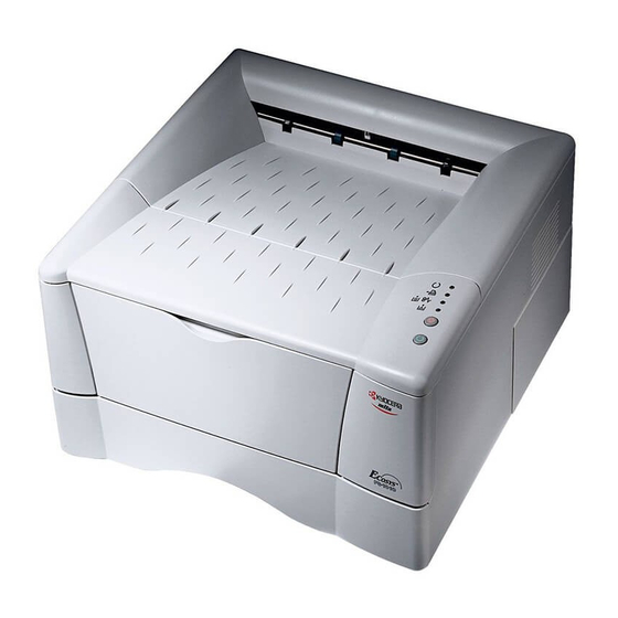
Page 14: Names Of Parts
9 Option interface slot cover 3 Face-up output tray 0 Parallel interface connector 4 Side cover ! USB interface connector 5 Operator panel @ Power switch 6 Front cover # AC inlet 7 Paper cassette Figure 1-2-1 Name of parts FS-1010... -
Page 15: Safety Information
Class I (1) laser products, and elsewhere is certified as a Class I laser product conforming to the requirements of IEC 825. (3) Laser caution label on the scanner unit The laser scanner unit has the following label affixed atop. Observe these cautionary statements and figures when handling the laser scanner unit. FS-1010... - Page 16 Use of controls or adjustments or performance of procedures other than those specified herein may result in hazardous radiation exposure. Label on the scanner unit (Inside the printer) Label on the left cover rear side European countries U.S.A/Canada Label on the fuser unit Figure 1-3-1 Caution labels FS-1010...
-
Page 17: Cdrh Regulations (U.s.a.)
Be sure to turn off printer power before connecting or disconnecting an interface cable to the printer. For protection against static discharge which may be applied to the printer’s internal electronics through the interface connector(s), keep any interface connector which is not in use capped using the protective cap supplied. FS-1010... -
Page 18: Environmental Requirements
Environmental requirements in chapter 1, the best print quality may not be expected and there will be an increased chance of paper jams. • Provide a sufficient clearances around the printer to ensure ventilation and ease of access. (See section Clearance on next page). FS-1010 1-10... -
Page 19: Clearance
Allow the necessary minimum clearance on all sides of the printer as diagrammed below. Figure 1-4-2 Clearances Ref. Clearance Dimensions Left 25 cm (9-7/8 inches) Front 50 cm (19-11/16 inches) Right 25 cm (9-7/8 inches) Back 40 cm (15-3/4 inches) Above 30 cm (11-13/16 inches) FS-1010 1-11... -
Page 20: Places To Avoid
• An easily accessible socket outlet must be provided near the equipment. WARNING As the disconnect device is not incorporated in the printer’s AC primary circuit, an easily accessible socket outlet must be provided near the equipment. FS-1010 1-12... -
Page 21: Removing The Printer
• Before removing the printer to a warm place, wrap it in a blanket, etc., before crating it. Allow approximately two to three hours after having moved after uncrated. Failure to observe the above may result in moisture condensation which will affect the performance of the printer. FS-1010 1-13... -
Page 22: About The Toner Container
To loosen and mix the toner inside before use, with the label side down, thoroughly shake the toner container 1 horizontally at least five times. Figure 1-5-1 Toner container handling CAUTION Do not attempt to disassemble or refill the toner container. FS-1010 1-14... -
Page 23: Toner Container Storage
CAUTION If the printer is shipped for return, etc., do not ship it with the toner container installed. Otherwise, toner may leak and contamination may result in the printer. FS-1010 1-15... - Page 24 I n s t a l l a t i o n / O p e r a t i o n Chapter 2...
- Page 25 Chapter 2 Contents 2-1 Unpacking ............................2-3 2-1-1 Unpacking and inspection ......................2-3 2-2 Installing the printer ........................2-4 2-2-1 Installing the toner container ..................... 2-4 2-2-2 Expanding memory ........................2-8 (1) Minimum memory requirements ..................2-8 (2) DIMM specifications ......................2-8 (3) Notes on handling DIMM .....................
-
Page 26: Unpacking
Carefully remove the printer. Toner container (TK-17) Cleaning cloth Printer Installation guide Kyocera Mita digital library Power cord CD-ROM Figure 2-1-1 Unpacking (1) Remove the tape on the rear side of the printer, and remove the two spacers and the printed notice from the paper cassette. -
Page 27: Installing The Printer
1. Open the top cover all the way. 2. Confirm that the lock lever #1 1 is in the release (forward) position. If not, pull it forward until it is in the release position. Figure 2-2-1 Confirming the lock lever #1 FS-1010... - Page 28 Shake the toner container 2 horizontally at least five times. This ensures that the toner is evenly distributed inside. Figure 2-2-2 Shaking the toner container 4. Carefully remove the protective seal 3. Figure 2-2-3 Removing the protective seal FS-1010...
- Page 29 5. Install the toner container 2 into the printer. 6. Push firmly on the top of the toner container 2 at the positions marked [PUSH HERE]. Figure 2-2-4 Installing the toner container FS-1010...
- Page 30 The period of time is approximately 15 minutes. If the toner low or replace toner indication does not go off after installing the new toner container, take the toner container out once, shake it well, then install again. FS-1010...
-
Page 31: Expanding Memory
2-2-2 Expanding memory The FS-1010 printer comes standard equipped with 16 MB of main memory on the main board. Printer memory can be expanded to up to the maximum 144 MB (16 + 128 MB). (1) Minimum memory requirements Refer to the table below for minimum memory requirements in various environments. -
Page 32: Notes On Handling Dimm
• Before touching a DIMM, touch a water pipe or other large metal object to discharge yourself of static electricity. While doing the work, it is recommended that you wear an antistatic wrist strap. • Touch the main board and DIMM only by the edges, not in the middle. Figure 2-2-6 Handling DIMM FS-1010... -
Page 33: Installing The Dimm
Turn the printer’s power switch off. Unplug the printer’s power cable and disconnect the printer from the computer or the network. Remove the side cover 1 as shown in the figure below. Step 2 Step 1 Remove one screw. Figure 2-2-7 Removing side cover FS-1010 2-10... -
Page 34: Testing The Expansion Memory
If the installation has been successful, the Available Memory item of the status page will show the expanded memory size corresponding to the amount of memory added. FS-1010 2-11... -
Page 35: Installing The Memory Card (Compactflash)
Remove the two screws 1 from the option interface slot cover 2 and remove the option interface slot cover (or network interface card 3 or the serial Interface board) . Figure 2-2-9 Removing the option interface slot cover FS-1010 2-12... - Page 36 Insert the memory card 4 in the slot. Insert as shown in the figure. Push it in all the way. Close and secure the option interface slot cover (or network interface card or the serial Interface board) . Figure 2-2-10 installing the memory card FS-1010 2-13...
-
Page 37: Installing The Network Interface Card
( or the serial Interface board) .Insert the network interface card 3 in the slot. Insert as shown in the figure. Push it in all the way. Secure the network interface card by using two screws Figure 2-2-11 installing the memory card FS-1010 2-14... -
Page 38: Using The Operator Panel
If you continued to press the key for 10 or more seconds, service status page is printed. • Switches between the MP tray and paper cassette when the paper runs out. • Prints out any unprinted page. FS-1010 2-15... -
Page 39: Remote Operation Panel
Displays printer settings and confirmation items. Changes the printer 3D image in real time according to the printer’s Monitor window status. For example, if you open the printer’s top cover, the top cover on the 3D image else open. FS-1010 2-16... -
Page 40: Maintenance/Adjustments
Maintenance/Adjustments Chapter 3... - Page 41 Chapter 3 Contents 3-1 Maintenance/Adjustments ......................3-3 3-1-1 Life expectancy of modules ....................... 3-3 3-1-2 Toner container .......................... 3-4 (1) When to replace the toner container ................... 3-4 (2) Notes on changing toner container ..................3-4 (3) Toner container replacement ....................3-5 (4) Toner saver mode (EcoPrint) ....................
-
Page 42: Maintenance/Adjustments
The table below shows the nominal life expectancy for modules. Detailed part information for each module (except toner container) can be found in Parts Catalog. Table 3-1-1 Life expectancy of modules Module Nominal life (pages) Remarks TK-17 Toner container 6,000 User-replaceable PU-42 Process unit 100,000 User-replaceable FS-1010... -
Page 43: Toner Container
• Keep magnetic media such as floppy disks away from the toner container. • Be sure to clean the parts as instructed in this section at the same timing of replacing toner container. • Use of the toner kit TK-17 is highly recommended for the optimum operation of the printer. FS-1010... -
Page 44: Toner Container Replacement
To replace the toner container, open the top cover. Pull lock lever #1 1 to the release [UNLOCK] position, then pull lock lever #2 2 to the release (right) position. Figure 3-1-1 Releasing Lock levers #1 and #2 Gently remove the old toner container 3. Figure 3-1-2 Removing the old toner container FS-1010... -
Page 45: Toner Saver Mode (Ecoprint)
The EcoPrint enables to reduce the amount of toner consumed on the page so as to save printing costs by drastically extending the toner container life. EcoPrint mode is factory-set to off and turned on by using the Remote Operation Panel (MENU) utility. For details refer to the printer’s User’s Manual. FS-1010... -
Page 46: Cleaning The Printer
Open the top cover 1 and front cover 2. Lift the process unit 3 together with the toner container out of the printer. Figure 3-1-4 Removing the process unit NOTE The drum in the process unit is sensitive to light. Never expose the drum even to normal office lighting (500 lux) for more than five minutes. FS-1010... -
Page 47: Cleaning The Registration Roller
Slide the charger cleaner knob (green colored) back and forth 2 to 3 times, then return it to its [CLEANER HOME POSITION]. Figure 3-1-6 Cleaning the main charger wire After cleaning is done, install the process unit in the printer, using the reverse manner as above. Close the front cover and top cover. FS-1010... -
Page 48: Updating The Firmware
The data to be downloaded are supplied in the following format: System firmware file name example A94K8000.bcmp compression Boot program is included. Version code: Version 80.00 ID code for Kyocera Machine code: FS-1010 (A94) Figure 3-1-9 Firmware program data format FS-1010... -
Page 49: Downloading The Firmware From The Parallel Interface
Confirm the status page shows the new firmware version (See Service information on the status page on page B-4). If downloading fails, the printer indicates an error display using the LED indicators. To identify error, refer to the table on page 3-12. FS-1010 3-10... -
Page 50: Downloading The Firmware From The Memory Card
Confirm the status page shows the new firmware version (See Service information on the status page on page B-4). If downloading fails, the printer indicates an error display using the LED indicators. To identify error, refer to the table on page 3-12. FS-1010 3-11... -
Page 51: Downloading Errors
Fast receiving error parallel cable between PC and printer’s interface flashing PC and printer connector. Defective parallel cable Replace parallel cable. If the corrective action above does not solve the problem, replace engine board (KP-882). See page 5-11. FS-1010 3-12... - Page 52 O p e r a t i o n O v e r v i e w Chapter 4...
- Page 53 Chapter 4 Contents 4-1 Electrophotographic system ......................4-3 4-1-1 Electrophotographic cycle ......................4-3 Process unit mechanism ......................4-4 (1) Main charging ........................4-5 Photo conductive drum ......................4-5 Charging the drum ........................4-6 (2) Exposure ..........................4-7 Laser scanner unit ........................4-8 Drum surface potential ......................
-
Page 54: Electrophotographic System
Each step is technically explained in the following sections. Laser scaner unit Process unit Main charging Exposure Drum Cleaning Developing Transfer Fusing Fuser unit Figure 4-1-1 Electrophotographic cycle The sections for main charging, exposure (drum), developing, and cleaning are modularized in one Process unit PU-42. FS-1010... -
Page 55: Process Unit Mechanism
# DLP screw B ⁄ Cleaning blade 6 Gear Z14-Z36 $ DLP screw A ¤ Sweep roller 7 Gear Z18-Z36 % Drum ‹ Waste toner reservoir 8 Free gear Z40 ^ Drum gear Z35H Figure 4-1-2 Process unit mechanism FS-1010... -
Page 56: Main Charging
The limit is approximately 500 lux for less than five minutes. If the drum (process unit) remains removed form the printer, it should be stored in a cool, dark place. Photo conductive layer Aluminum base cylinder Figure 4-1-3 Photo conductive drum FS-1010... -
Page 57: Charging The Drum
Due to high-voltage scorotron charging, the charging wire can get contaminated by oxidization after a long rum. Therefore, it must be cleaned periodically from time to time using the method explained in chapter 3. Cleaning the charging wire prevents print quality problems such as black streaks. FS-1010... -
Page 58: Exposure
The laser beam (780 nm wavelength) beam is dispersed as the polygon motor (polygon mirrors) revolves to reflect the laser beam over the drum. Various lenses and mirror are housed in the scanner unit, adjust the diameter of the laser beam, and focalize it at the drum surface. FS-1010... -
Page 59: Laser Scanner Unit
Bends the very first shot of a laser scan towards the beam detection sensor (6). 6 Pin photo sensor When shone by the sensor mirror above, this photo-sensor generates a trigger signal for the engine controller to start activating the paper feeding system. FS-1010... -
Page 60: Drum Surface Potential
Note that the area to be printed black has the low potential, constituting a “positively exposed” image. Laser beam Exposed surface potential approximately +60 to +80 V Charged surface potential +400±15 V layer Drum Aluminum cylinder Figure 4-1-7 Drum surface potential FS-1010... -
Page 61: Development
A is approximately 0.3 mm.) The non-exposed areas of the drum F repel the positively charged toner as these areas maintain the positive charge. The developing roller A is also AC-biased to ensure contrast in yielding by compensating the toner’s attraction and repelling action during development. FS-1010 4-10... -
Page 62: Transfer
-2.5 kV/-6 µA for thicker paper. On the other hand, the bias current is reduced to -1.8 kV/-6 µA for thin paper. FS-1010 4-11... -
Page 63: Fusing
The temperature of the heat roller is constantly monitored by the engine board using the thermistor and triac. Should the temperature of the heat roller exceed the predetermined value, the thermal cutout is activated to effectively disconnect the heater (halogen) lamp from power. FS-1010 4-12... -
Page 64: Fuser Unit Mechanism
9 Separator(s) 2 Idle gear Z34 6 Press roller 0 Thermistor 3 Exit gear Z23 7 Heater lamp [500±25 W] ! Exit pulley(s) 4 Idle gear Z18 8 Thermal cutout @ Lower exit roller Figure 4-1-11 Fuser unit mechanism FS-1010 4-13... -
Page 65: Cleaning
The residual charge is canceled by exposing the drum B to the light emitted from the eraser lamp E. This lowers the electrical conductivity of the drum surface making the residual charge on the drum surface escape to the ground. FS-1010 4-14... -
Page 66: Paper Feeding System
& Exit pulley 4 Face-up output tray ! Upper registration roller * Upper exit roller 5 Process unit @ Transfer roller ( Exit pulley 6 Fuser unit # Drum 7 Feed roller $ Heat roller Figure 4-2-1 Paper feeding path FS-1010 4-15... -
Page 67: Paper Feed Control
Bias board Engine board 1 MP feed roller 2 Feed roller 3 Lower registration roller 4 Upper registration roller 5 Transfer roller 6 Heat roller 7 Lower exit roller 8 Upper exit roller Figure 4-2-2 Paper feed control FS-1010 4-16... -
Page 68: Paper Feeding Mechanism
@ Transfer roller # TC gear Z18 ^ Heat gear Z33 ( Upper exit roller $ Press roller & Lower exit roller ) Exit gear Z23 UP % Heat roller * Exit gear Z23 Figure 4-2-3 Paper feeding mechanism FS-1010 4-17... -
Page 69: Electrical Control System
5 Bias board (KP-884) & Thermal cutout K Cassette switch * Thermistor indicator (LED) E Data indicator (LED) L Registration sensor ( Paper feeder interface F On line indicator (LED) M Paper sensor connector Figure 4-3-1 Electrical parts layout FS-1010 4-18... -
Page 70: Operation Of Circuit Boards
DIMM SDCSN0 CTS, DSR, RXD Slot SDD31-0 RSSEL SDCLK [Debugger connector] SDD31-16 YC09 SDRAM SDA12-0 DBTXD DBRXD, DBCLK SDCSN1-2 SDCLK 3.3 V Regulator +5 V1 +3.3 V1 SDRAM Data bus SDD31-0 Figure 4-3-2 Main board circuit block diagram FS-1010 4-19... -
Page 71: Engine Board
Zero AC input cross Interlock signal 24 V DC High voltage switch detection output circuit Triac output circuit circuit Exit sensor Thermistor Power supply board High voltage board Figure 4-3-3 Engine board circuit block diagram FS-1010 4-20... -
Page 72: Eraser Lamp Control Circuit
The LED indicator “Call service 5300” error is then displayed. Engine board +24V Eraser lamp cotrol circuit 3 Q14 ERASERN P25/ASCK0 Eraser lamp YC05 ERASPW ERASER PGND ERRDYN P16/ANI6 DZ01 Figure 4-3-4 Eraser lamp control circuit FS-1010 4-21... -
Page 73: Heater Lamp Control Circuit
P50/A8 QA03-a ZCROSS P00/INTP0 Power supply unit Bias board AC input Zero Thermal cutout cross signal High detection Heat roller voltage circuit board +24 V Heater lamp (PC2) Triac Photo-triac (TRC1) Thermistor Figure 4-3-5 heater lamp control circuit FS-1010 4-22... - Page 74 #3, the level at pin #1 becomes low. Since pin #1 is wired to the output line for the HEAT signal, the HEAT signal is enforced to be low regardless the behavior of CPU (U01), thus preventing possible heat overrun. The LED indicator “Call service 6110” error is then displayed. FS-1010 4-23...
- Page 75 − cross point Conductivity staus of Triac (TRC1) Variation No.2 (Duty 80 %) − Variation No.3 (Duty 60 %) − Variation No.4 (Duty 40 %) − Variation No.5 (Duty 0 %) − Figure 4-3-6 heater lamp turn-on variations FS-1010 4-24...
-
Page 76: Polygon Motor Control Circuit
Engine board Laser scanner unit Polygon motor control circuit +24V Polygon motor PLGDR PGND 17,008 rpm +24V PLGRDYN PGND Main board PLGDRN control IC PLGRDYN (IC1) PLGCLK YC06 1700.8 Hz PLGCLK PGND Figure 4-3-7 Polygon motor control circuit FS-1010 4-25... -
Page 77: Power Supply Board
Photo- Over voltage coupler detection (PC1) circuit +24 V Photo- ZCROSS Transistor Heater coupler (Q8) lamp (PC3) Triac Zero cross signal (TRC1) detection circuit Thermal cutout Photo- HEAT Triac (PC2) Figure 4-3-8 Power supply board circuit block diagram FS-1010 4-26... -
Page 78: Bias Board
24 V DC SWIN Paper sensor RTHVDR, HVISEL PSEL1, PSEL2 FANL FANH HEATN, ZCROSS EXTIN, THERM +24 V 275 V DC + AC HVCLK Developing bias output circuit Developing roller Figure 4-3-9 Bias board circuit block diagram FS-1010 4-27... -
Page 79: High Voltage Board
THVDR, Transfer RTHVDR roller Control PSEL1, PSEL2 driver HVISEL circuit Transfer bias output positive voltage Power supply board circuit +24V2 +24V2 Interlock switch +24V1 FAN, HEATN, SLEEP ZCROSS, THERM, EXITN Figure 4-3-10 High voltage board circuit block diagram FS-1010 4-28... -
Page 80: Interlock Switch
Projection Engine board, Bias board, etc. Front cover Power supply unit High voltage Interlock output circuit switch Triac, etc. +24V2 +24V1 +24 V DC output Machine left side view High voltage board Cooling fan Figure 4-3-11 Interlock switch FS-1010 4-29... - Page 81 D i s a s s e m b l y Chapter 5...
- Page 82 Chapter 5 Contents 5-1 General instructions ........................5-3 5-1-1 Screw/hardware ......................... 5-3 5-1-2 Before starting disassembly ...................... 5-3 5-2 Disassembly ............................. 5-4 5-2-1 Removing the process unit ......................5-4 5-2-2 Removing the principal outer covers ..................5-5 (1) Removing the top cover/face-down output tray ..............5-5 (2) Removing the right cover .....................
-
Page 83: General Instructions
The printer use electrostatic sensitive parts inside (on circuit boards, Laser scanner unit, etc.). Provide an antistatic (discharging) device, such as a wrist strap, that can effectively discharge your body before touching the circuit boards, the laser scanner unit, etc. FS-1010... -
Page 84: Disassembly
After removing the process unit, seal it in the protective bag and place it on flat surface. Do not place the process unit in a dusty area. Do not give impact to the process unit. Do not place floppy disks near the process unit. FS-1010... -
Page 85: Removing The Principal Outer Covers
5-2-2 Removing the principal outer covers (1) Removing the top cover/face-down output tray 1. Open the top cover 1. 2. Remove two screws 2. 3. Remove the top cover/face-down output tray 3. Figure 5-2-2 Removing the top cover/face-down output tray FS-1010... -
Page 86: Removing The Right Cover
3. Unlatch the six snaps 3 and one hook hole 4 on the chassis, remove the right cover 5. Figure 5-2-3 Removing the right cover (3) Removing the left cover 1. Unlatch the six snaps 1 and two hook holes 2 on the chassis, remove the left cover 3. Figure 5-2-4 Removing the left cover FS-1010... -
Page 87: Removing The Feed Roller
1. Remove the paper cassette and the process unit. (See page 5-4) 2. Stand the machine the front side up. 3. Move the feed roller in the direction A, and remove the feed roller 1. Figure 5-2-5 Removing the feed roller FS-1010... -
Page 88: Removing The Mp Tray Feed Roller
1. Remove the engine board. (See page 5-11) 2. Remove one screw 1. 3. Remove the grounding plate 2. 4. Remove one stop ring 3. 5. Remove the MP feed clutch 4. Figure 5-2-6 Removing the MP feed clutch FS-1010... - Page 89 9. While pressing the latch 9 by using the driver and then remove the MP feed unit 0. Figure 5-2-7 Removing the MP feed unit 10. Remove the stop ring ! and then remove the MP feed roller @. Figure 5-2-8 Removing the MP feed roller FS-1010...
-
Page 90: Removing The Transfer Roller
1. Remove the process unit. (See page 5-4) 2. Remove the transfer roller 1 from the both bushes. Paper passing direction Long Short Transfer roller Bush Gear Bush (Black colored) Spring (Black colored) Bush Spring Figure 5-2-9 Removing the transfer roller FS-1010 5-10... -
Page 91: Removing The Principal Circuit Boards
1. Remove the top cover/face-down output tray and right cover (See pages 5-5 and 5-6). 2. Remove all (ten) connectors from the engine board 1. 3. Remove three screws 2. 4. Remove the engine board 1. Figure 5-2-10 Removing the engine board FS-1010 5-11... -
Page 92: Removing The Main Board
2. Remove the top/face-down output tray and right cover (See pages 5-4 and 5-5). 3. Remove two connectors 1 from main board 2. 4. Remove six screws 3. 5. Remove the controller box (with main board) 4. Figure 5-2-11 Removing the controller box (with main board) FS-1010 5-12... - Page 93 6. Remove two screws 5 at the back of the main board 2. 7. Remove three screws 6 from the parallel interface connector 7 and USB connector 8. 8. Remove the main board 2. Figure 5-2-12 Removing the main board FS-1010 5-13...
-
Page 94: Removing The Power Supply Board And High Voltage Board
5. Remove the power supply board 2 and high voltage board 4. (Note: The high voltage board 4 is directly connected to the bias board 5.) 6. Separate the high voltage board 4 from the power supply board 2. Figure 5-2-13 Removing the power supply board and high voltage board FS-1010 5-14... -
Page 95: Removing The Bias Board
5. Remove one connector 1 from the bias board 2. 6. Remove five screws 3. 7. Remove the bottom cover 4. 8. Remove the two connectors 5 from the bias board 2. 9. Remove the bias board 2. Figure 5-2-14 Removing the bias board FS-1010 5-15... -
Page 96: Removing The Main Motor And Drive Unit
2. Remove the top cover/face-down output tray and right cover (See pages 5-5 and 5-6). 3. Remove three connectors 1 from the main motor 2. 4. Remove four screws 3. 5. Remove main motor 2. Figure 5-2-15 Removing the main motor FS-1010 5-16... - Page 97 6. Remove the engine board (See page 5-11). 7. Remove wires from wire saddles 4 on the cord cover 5. 8. Remove one screw 6. 9. Remove the cord cover 5. 5-2-16 Removing the cord cover FS-1010 5-17...
- Page 98 10. Remove one screw 6. 11. Remove the grounding plate 7. 12. Remove three stop rings 8. 13. Remove MP feed clutch 9, feed clutch 0, and registration clutch !. Figure 5-2-17 Removing the clutches FS-1010 5-18...
- Page 99 14. Remove the four screws @. 15. Remove the drive unit #. Figure 5-2-18 Removing the drive unit FS-1010 5-19...
-
Page 100: Removing And Splitting The Fuser Unit
2. Remove the top cover/face-down output tray, right and left covers. (See page 5-5, 5-6) 3. Remove the rear side cover 1. 4. Remove the two connectors 2. 5. Remove two screws 3. 6. Remove the fuser unit 4. Figure 5-2-19 Removing the fuser unit FS-1010 5-20... - Page 101 7. Remove two screws 5. 8. Open and split the fuser unit 4. Figure 5-2-20 Splitting the fuser unit FS-1010 5-21...
-
Page 102: Removing The Separators
1. Remove and split the fuser unit (See page 5-20). 2. Loosen the stopper screws 1. 3. Hold the separators 2 upright, and remove the separators 2 and separator springs 3. Step 1 Step 2 Figure 5-2-21 Removing the separators FS-1010 5-22... -
Page 103: Removing The Heater Lamp
4. Remove the heater lamp 3 form the lamp B holder 4. 5. Remove the heater lamp 3 from the heat roller 5. Machine right side Machine left side Long Projection Short Figure 5-2-22 Removing the heater lamp FS-1010 5-23... -
Page 104: Removing The Heat Roller
3. Press the lamp A holder 1 away from the heat roller. Pull up both heat R bush 2 and heat L bush 3 at the same time. Figure 5-2-23 Removing the heat R bush and heat L bush FS-1010 5-24... - Page 105 3. Remove the heat gear Z33 4, heat R bush 2, and heat L bush 3 from the heat roller 5. Figure 5-2-24 Removing the heat roller FS-1010 5-25...
-
Page 106: Removing The Thermistor
1. Remove and split the fuser unit (See page 5-20). 2. Remove the heater lamp (See page 5-23). 3. Remove the heat roller (See page 5-24). 4. Remove one screw 1. 5. Remove the thermistor 2. Figure 5-2-25 Removing the thermistor FS-1010 5-26... -
Page 107: Removing The Thermal Cutout
1. Remove and split the fuser unit (See page 5-20). 2. Remove the heater lamp (See page 5-23). 3. Remove the heat roller (See page 5-24). 4. Remove the two screws 1. 5. Remove the thermal cutout 2. Figure 5-2-26 Removing the thermal cutout FS-1010 5-27... -
Page 108: Removing The Press Roller
The press roller is extremely hot immediately after the printer was running. Allow substantial period of time until it cools down. 1. Remove and split the fuser unit (See page 5-20). 2. Remove the press roller 1 from the fuser unit 2. Figure 5-2-27 Removing the press roller FS-1010 5-28... -
Page 109: Removing The Laser Scanner Unit And The Eraser Lamp
3. Remove four connectors 1. 4. Remove five screws 2 and four screws 3. 5. While keeping the ground joint plate 4 away from the LSU plate 5, remove the LSU plate. Figure 5-2-28 Removing the LSU plate FS-1010 5-29... - Page 110 5. Remove three screws 6. 6. Remove one connector 7 from the laser scanner unit 8. 7. Remove the laser scanner unit 8. Figure 5-2-27 Removing the laser scanner unit FS-1010 5-30...
- Page 111 8. Remove the eraser lamp 9. 5-2-28 Removing the eraser lamp FS-1010 5-31...
-
Page 112: Removing The Main Charger Unit
3. Draw the main charger unit 3 in the direction of arrow A, then pull it out in the direction of arrow B. 5-2-29 Removing the main charger unit When refitting the main charger unit 3, hold terminal 4 down C, then push CAUTION frontwards. Use care not to deform the terminal 4. FS-1010 5-32... -
Page 113: Troubleshooting
T r o u b l e s h o o t i n g Chapter 6... - Page 114 Chapter 6 Contents 6-1 Troubleshooting ..........................6-3 6-1-1 Error messages ......................... 6-3 (1) Messages ..........................6-4 Normal messages ........................6-5 Maintenance messages ......................6-6 Error messages ........................6-8 6-1-2 Service error indications ......................6-10 (1) 2000 - Main motor error ..................... 6-10 (2) 4000 - Laser scanner unit [Polygon motor] error ...............
-
Page 115: Troubleshooting
On line indicator Data indicator Paper empty/Paper jam indicator Toner indicator Cancel key Go key Figure 6-1-1 Indicators and control keys For explanation on the basic function of the indicators and the keys, refer to pages 2-14. FS-1010... -
Page 116: Messages
Fast Slow flashing flashing Green By using the Remote Operation Panel utility to monitor the printer’s status from the computer, the error message can be is displayed on the computer’s screen when an error occurs. FS-1010... -
Page 117: Normal Messages
The printer then warms up and goes online. (You can set the amount of time before the printer enters sleep mode from the Remote Operation Panel utility.) FS-1010... -
Page 118: Maintenance Messages
Go key to switch the paper source. The printer prints on the paper size set in that particular paper source. Note: Feeding the paper having a paper size which does not match the current paper size from the MP tray can cause paper jam. FS-1010... - Page 119 (See page 3-4) (No indication patterns available) The print job cannot be done at current Warning resolution because there is not enough image adapt indication internal memory. patterns Try adding memory or changing available) resolution. (No indication patterns available) FS-1010...
-
Page 120: Error Messages
You can abandon printing by pressing the Cancel key. Printing cannot continue because there Memory overflow is not enough memory. Press GO Try adding more memory. Press the Go key to resume printing. You can abandon printing by pressing the Cancel key. FS-1010... - Page 121 (No indication patterns available) This message appears when the printer Format error is in the ready state and the memory MemoryCard indication card is not formatted, and therefore patterns cannot be read or written. available) Format the memory card. FS-1010...
-
Page 122: Service Error Indications
CN1 on main motor goes high, then low, within 3 seconds from pin 8 (MOTORN) goes low? Replace engine board (KP-882). See page 5-11. Replace main motor. See page 5-15. If not solved, check or replace drive unit. See page 5-16. FS-1010 6-10... -
Page 123: 4000 - Laser Scanner Unit [Polygon Motor] Error
2 (PLGRDYN) and pin 3 (PLGDRN) of YC06 on engine board Turn power switch on. Continued (KP-882). to next page. Turn power switch off, then on. Replace harness (S02779) between engine bard and laser scanner unit. End. FS-1010 6-11... - Page 124 Continued from previous page. Replace engine board (KP-882). See page 5-11. Turn power switch on. Replace main board (KP-888). See page 5-12. End. Turn power switch on. End. Replace harness (S02770) between engine board and main board. FS-1010 6-12...
-
Page 125: 4200 - Laser Scanner Unit [Pin Photo Diode] Error
(KP-888) output pulse signal*, within 0.1 second after pin 4 (OUTPEN) goes high, then low? *: Pin photo diode detect horizontal synchronization signal (Frequency: 1417 Hz, Low level width: 10 µs) Continued Continued to next page. to next page. FS-1010 6-13... - Page 126 Turn power switch on. Replace harness (S02502) between main End. board and laser scanner unit. End. Turn power switch on. Replace harness (S02770) between main board and engine board. End. Replace harness (S02770) between main board and engine board. FS-1010 6-14...
-
Page 127: 5300 - Eraser Lamp Error
? Turn power switch off, then on. Print a status page. Does pin 2 (ERASER) of YC05 on engine board (KP-882) remain low? Replace engine board (KP-882). See page 5-11. Replace eraser lamp [PWB] (KP-790). See page 5-29. FS-1010 6-15... -
Page 128: 6000 - Fuser Unit Error
(KP-884). connector. "6000" error Open (infinite)? shown? Replace thermal cutout or heater lamp. See page 5-26 or 5-23. Replace bias board or high voltage board or power supply board. See page 5-15 or 5-14. End. FS-1010 6-16... -
Page 129: 7980 - Waste Toner Full [Total Page Count Less Than 100,000 Pages Of Printing]
Printer indicators Shake the process unit horizontally. Turn power switch off, then on. "7980" error shown? Replace the process unit. Turn power switch off, then on. "7980" error shown? End. Replace the waste toner sensor or engine board. FS-1010 6-17... -
Page 130: 7990 - Waste Toner Full [Total Page Count More Than 100,000 Pages Of Printing]
(9) F020 - Controller RAM read/write error Remove the expansion memory (DIMM). Turn power switch off, then on. If not solved, replace main board. If solved, replace the expanding memory (See pages 2-8 and 5-12). Printer indicators Remote Operation Panel Call service F020:nnnnnn FS-1010 6-18... -
Page 131: F030 - Controller System Error
Printer indicators Remote Operation Panel Call service F040:nnnnnn (12) F050 - Engine ROM checksum error Turn power switch off, then on. If not solved, replace engine board (See page 5-12). Printer indicators Remote Operation Panel Call service F050:nnnnnn FS-1010 6-19... -
Page 132: Print Quality Problems
(5) Black horizontal (6) Black vertical (7) Unsharpness (8) Gray streaks streaks background See page 6-26. See page 6-24. See page 6-25. See page 6-27. (9) Dirt on the top edge or back of the paper See page 6-28. FS-1010 6-20... -
Page 133: Completely Blank Printout
Replace the high voltage board if high voltage potential is not available on the board (See page 5-14). Check the laser scanner unit. • The scanner components within the scanner may be disordered. Replace the laser scanner unit if necessary (See page 5-29). FS-1010 6-21... -
Page 134: All-Black Printout
• Make sure the bias from the high voltage board correctly arrives at the process unit. Check high voltage potential at the high voltage board. • Check the high voltage output on the high voltage board. Replace the high voltage board if high voltage potential is not available on the board. FS-1010 6-22... -
Page 135: Dropouts
• Check the transfer bias output on the high voltage board. This requires removal of the left cover and the test equipment. Replace the high voltage board if high voltage potential is not available on the board (See page 5-10). FS-1010 6-23... -
Page 136: Black Dots
• The drum axle in the process unit and its counter part, the grounding tab in the printer, must be in a good contact. If necessary, apply a small amount of electro-conductive grease onto the tab. The drum may be defective. • Replace the process unit. FS-1010 6-24... -
Page 137: Black Vertical Streaks
• A streak of toner remaining on drum after printing means that the cleaning blade (in the process unit) is not working properly. Replace the process unit. Defective magnet roller (in the process unit). • Replace the process unit. FS-1010 6-25... -
Page 138: Unsharpness
• The EcoPrint mode can provides faint, unsharp printing because it acts to conserve toner for draft printing purpose. For normal printing, turn the EcoPrint mode off by using the Remote operation panel. For details refer to the printer’s User’s Manual. FS-1010 6-26... -
Page 139: Gray Background
• If a process unit which is known to work normally is available for check, replace the current process unit in the printer with the normal one. If the symptom disappears, replace the process unit with a new one. FS-1010 6-27... -
Page 140: Dirt On The Top Edge Or Back Of The Paper
Check the transfer roller. • If the transfer roller is contaminated with toner, clean the transfer roller using a vacuum cleaner; or by continuously printing a low-density page until the symptom has faded away. FS-1010 6-28... -
Page 141: Repetitive Defects Gauge
[25 mm] Upper registration roller [38 mm] Lower registration roller [50 mm] Transfer roller [61 mm] Heat roller, Press roller (Fuser unit) [63 mm] Developing roller (Process unit) [94 mm] Drum (Process unit) Figure 6-1-2 Repetitive defects gauge FS-1010 6-29... -
Page 142: Correcting A Paper Jam
(1) Jam at the face-down and face-up trays 1. Open the face-up tray and remove the jammed paper as shown in the figure. Figure 6-1-3 Jam at the face-down and face-up trays FS-1010 6-30... - Page 143 (3) Jam inside the printer 1. Open the top cover and front cover. 2. Take the process unit together with the toner container out of the printer. 3. Remove the jammed paper. Figure 6-1-5 Jam inside the printer FS-1010 6-31...
- Page 144 Appendix A...
- Page 145 Appendix A Contents Timing charts ............................A-3 1. Option paper cassette feeding, two A4 size papers ................ A-3 2. Option paper cassette feeding, two legal size papers ..............A-4 3. Option paper cassette feeding, two letter size papers ..............A-5 4.
-
Page 146: Timing Charts
Timing charts 1. Option paper cassette feeding, two A4 size papers FS-1010... -
Page 147: Option Paper Cassette Feeding, Two Legal Size Papers
2. Option paper cassette feeding, two legal size papers FS-1010... -
Page 148: Option Paper Cassette Feeding, Two Letter Size Papers
3. Option paper cassette feeding, two letter size papers FS-1010... -
Page 149: Mp Tray Feeding, Two A4 Size Papers
4. MP tray feeding, two A4 size papers FS-1010... -
Page 150: Mp Tray Feeding, Two Legal Size Papers
5. MP tray feeding, two legal size papers FS-1010... -
Page 151: Mp Tray Feeding, Two Letter Size Papers
6. MP tray feeding, two letter size papers FS-1010... -
Page 152: Wiring Diagram
Wiring diagram FS-1010... -
Page 153: Status Page
S t a t u s P a g e Appendix B... - Page 154 Appendix B Contents Status page ............................. B-3 Printing the service status page ......................B-3 Details of service information ......................B-4...
- Page 155 1 Connect the printer to the PC via the parallel interface. 2 Ensure that the printer is ready to print. 3 At the DOS prompt, type: echo !R! STAT 1; EXIT; >lpt1: The service status page is printed. (If you omit ‘1,’ a user status page is printed.) FS-1010...
- Page 156 Most of these service information on the status page are alphanumerically-coded. Each item is explained on the next page. Details of service information Controller firmware version* Released date of the firmware Released: 23/July/2001 Software version: Service information [A003][28.00C][17/05] Total page 9690 /t/P00/S00/F00/N00 /0020/0020/1061/8811/ /RS2/00/AI.E/G/1 /0200800000000000/0000000000000000/00000000000E1000/0000000000000000 /00800080/00800080/00800080/80000000/00000000/00000000/00000000/ /00000000/00000000/00000000/00000000/00000000/00000000/00000000/ SPD1:0203040508090A0B0C0D0F101112131415161718191A1B1C1D1E1F202122235E SN:SPL92000010 Service information FS-1010...
-
Page 157: Total Page
% ^ & * ( /0200800000000000/0000000000000000/00000000000E1000/0000000000000000 /00800080/00800080/00800080/80000000/00000000/00000000/00000000/ ⁄ /00000000/00000000/00000000/00000000/00000000/00000000/00000000/ ¤ SPD1:0203040508090A0B0C0D0F101112131415161718191A1B1C1D1E1F202122235E ‹ SN:SPL92000010 › Example Meaning Description 1 [A003] Engine ROM version 2 [28.00C] Boot ROM version 3 [17/05] Internal use 4 Total page 9690 Total count page 5 /t Internal use FS-1010... - Page 158 In + inch source (MP tray/Printer’s cassette/Optional paper feeder’s cassette) % RS2 Serial interface mode RS2= RS-232C, RS4= RS422A (Shown only optional serial interface board is installed) Average print coverage (total) ^ /00 Calibration table setting Hexadecimal (FRPO I4) FS-1010...
- Page 159 Fuser temperature, paper weight, and duplex print setting value ¤ /00000000/... Media type attribute setting Media type 1 to 28 (Reserved: 12 to 20) For print density setting value ‹ SPD1:02030405... DRAM SPD (slot 1) › SN:SPL9200010 Serial number for the printer FS-1010...
- Page 160 Appendix C...
- Page 161 Appendix C Contents Parallel interface ............................ C-3 Selecting the parallel interface mode ....................C-3 Parallel interface pin assignment ......................C-4 Parallel interface signals ........................C-5 USB interface ............................C-6 USB interface pin assignment ......................C-6 Serial interface (Optional) ........................C-7 Changing the serial interface configuration ..................
-
Page 162: Parallel Interface
Type at the DOS prompt... echo !R! FPRO O0, 0; EXIT; lpt1: Normal echo !R! FPRO O0, 1; EXIT; lpt1: High-speed echo !R! FPRO O0, 5; EXIT; lpt1: Nibble echo !R! FPRO O0, 70; EXIT; lpt1: Automatic* *: Factory-set default. FS-1010... -
Page 163: Parallel Interface Pin Assignment
(SELECT) nInit (INIT*) nAutoFd (AUTOFD*) nFault (FAULT*) Not defined Not defined Pull-up (1kΩ) Logic ground Not defined Chassis ground Not defined Pull-up (1kΩ) Peri-logic H (VCC) nSelect In (SELECTI*) Maximum rated current for pin 18 is 400 mA (fused). FS-1010... -
Page 164: Parallel Interface Signals
This signal is high when the printer’s power is on. Power Ready (Pin 35) This signal is used in some versions of the Centronics interface to Select In [NSelectIn] enable the computer to force the printer on-line. In high-speed mode, it is used as an interrupt. FS-1010... -
Page 165: Usb Interface
5 meters (16 feet). Transfer mode Full speed (max. 12 Mbps) Power control Self-power device USB interface pin assignment Shell Signal Description Vbus Power supply (+5 V) Data transmission Data transmission Signal ground Shell Shield Shell: Shield FS-1010... -
Page 166: Serial Interface (Optional
Before touching the main board, touch a water pipe or other large metal object to discharge yourself of static electricity. While doing the work, it is recommended that you wear an antistatic wrist strap. Touch the main board only by the edge. FS-1010... - Page 167 RS-232C to RS-422A, for example, carefully remove the jumper connector 3 on the serial interface board 2. Reconnect to the pin position as shown in the diagram. Replace the serial interface board 2 back into the printer. Secure the board by the thumb screws. FS-1010...
-
Page 168: Serial Interface Signals
The voltage levels of the RS-422A signals are equivalent to those of the RS-232C signals except the signals used for transmission and reception. RS-422A interface voltage levels The interface signal voltage levels for RS-422A conforms with the EIA RS-422A standards. The differential voltage ranges is from 200 mV to 6 V. FS-1010... -
Page 169: Connector Configurations
RS-422A configuration by referring to the diagram (last) below. RS-232C - For computers with a DB-9 connector Printer Computer serial port (DB-25) serial port (DB-9) RS-232C - For computers with a DB-25 connector Printer Computer serial port (DB-25) serial port (DB-25) FS-1010 C-10... -
Page 170: Rs-422A
The serial interface supports the full baud rate of: 1200, 2400, 4800, 9600, and 19200, 38400, 57600 and 115.2 k (bps). For adjusting serial interface parameters including baud rate, parity, etc., refer to optional Serial interface board User’s Manual. FS-1010 C-11... - Page 171 Via Verdi 89/91 20063 Cernusco sul Naviglio (Milano) Italy Headquarters: Phone: 02-92179 1 225 Sand Road, P.O. Box 40008, Fairfield, New Jersey 07004-0008, S.A. KYOCERA MITA BELGIUM N.V. U.S.A. Hermesstraat 8A, 1930 Zaventem, Belgium Phone: (973) 808-8444 Phone: (02) 7209270 KYOCERA MITA FRANCE S.A.
- Page 172 KYOCERA MITA MEXICO, S.A. DE C.V. Av. 16 de Septiembre #407 Col. Santa Inés, 02130 Azcapotzalco México, D.F. Mexico TEL : (5) 383-2741 FAX : (5) 383-7804 ©2001 KYOCERA MITA CORPORATION is a trademark of Kyocera Corporation is a registered trademark of KYOCERA MITA CORPORATION...
Need help?
Do you have a question about the Ecosys FS-1010 and is the answer not in the manual?
Questions and answers