Table of Contents
Advertisement
Advertisement
Table of Contents

Related Manuals for Ubiquiti airFiber 5


Summary of Contents for Ubiquiti airFiber 5
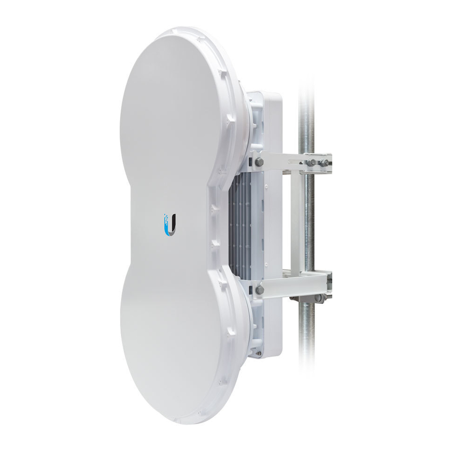
- Page 1 5 GHz Full Duplex Point-to-Point Gigabit Radio Models: AF-5, AF-5U...
-
Page 2: Table Of Contents
MGMT Port Ethernet Settings ........... .30 Ubiquiti Networks, Inc. - Page 3 Ubiquiti Networks Support ........
-
Page 4: Introduction
Power Cord Quick Start Guide (Qty. 2) (50V, 1.2A) TERMS OF USE: Ubiquiti radio devices must be professionally installed. Shielded Ethernet cable and earth grounding must be used as conditions of product warranty. TOUGHCable ™ is designed for outdoor installations. It is the customer’s responsibility to follow local country regulations, including operation within legal frequency channels, output power, and Dynamic Frequency Selection (DFS) requirements. - Page 5 4X to 0.25X LOCAL MANAGEMENT DATA No Ethernet Link SPEED SPEED Ethernet Link Established Random Flashing Ethernet Activity 10 Mbps Speed 100 Mbps No Ethernet Link Ethernet Link Established Random Flashing Ethernet Activity 10/100 Mbps Speed 1000 Mbps Ubiquiti Networks, Inc.
-
Page 6: Link Planning
• (Recommended) 2 Outdoor GigE PoE surge protectors Note: For guidelines about grounding and lightning protection, follow your local electrical regulatory codes. • Outdoor, shielded Category 6 (or above) cabling and shielded RJ-45 connectors are required for all wired Ethernet connections. Ring Configuration Ubiquiti Networks, Inc. -
Page 7: Installation Overview
1. Push the button and slide the port cover down to access cable ports. (The port cover cannot be completely removed.) 4. Connect the Power Cord to the power port on the GigE PoE Adapter. Connect the other end of the Power Cord to a power source. Ubiquiti Networks, Inc. -
Page 8: Airfiber Configuration
Download the firmware at: downloads.ubnt.com/airfiber 6. Enter the requirements of your link, and then click Calculate. Adjust the values as needed to get the optimal result, and then write down the settings needed for your configuration. Ubiquiti Networks, Inc. - Page 9 ). You can omit zeroes and use colons, similar to IPv6 format. Note: The airFiber Configuration Interface supports IPv6 formats excluding dotted quad and “::” (double-colon) notation. ASCII Enter a combination of alphanumeric characters (0-9, A-Z, or a-z). 10. Click Change and then click Apply. Ubiquiti Networks, Inc.
-
Page 10: Hardware Installation
4. Attach the Upper Mount Bracket with Elevation Rod to the I-Bracket using two M8x14 Serrated Flange Bolts. Note: Ensure that the orientation of the Upper Mount Bracket matches the illustration below, with the Elevation Rod on the correct side. Ubiquiti Networks, Inc. - Page 11 Insert the two M10x100 Carriage Bolts into the Azimuth Support Bracket that has two slotted holes. b. Slide the slotted hole of the other Azimuth Support Bracket over one M10x100 Carriage Bolt. c. Place one M10 Serrated Flange Nut on each M10x100 Carriage Bolt. Ubiquiti Networks, Inc.
- Page 12 Slide the open slot of each Pole Clamp over the corresponding M10x150 Carriage Bolt. c. Tighten the M10 Serrated Flange Nuts of the M10x150 Carriage Bolts to secure the mounting assembly to the pole. Ubiquiti Networks, Inc.
-
Page 13: Connecting Ethernet
1. Remove the nut from the Grounding Point. OVERLOAD MASTER LINK REMOTE RESET 4X to 0.25X LOCAL MANAGEMENT DATA SPEED SPEED 2. Attach a ground wire (min. 8 AWG or 10 mm ) to the lug and replace the nut to secure the wire. Ubiquiti Networks, Inc. - Page 14 GigE PoE surge protectors. Install the first surge protector within one meter of the airFiber Data port, and install the second surge protector at the ingress point of the location housing the wired network equipment. Ubiquiti Networks, Inc.
-
Page 15: Alignment
1. Ensure that the following bolts and nuts are loose: • Four Pre-Installed M10x25 Flanged Bolts on the airFiber radio (two on each side) • Four M10 Hex Nuts used to lock the elevation alignment on the Upper Mount Bracket (two on each side) Ubiquiti Networks, Inc. - Page 16 11. For each airFiber radio, close the port cover and ensure Note: Do NOT make simultaneous adjustments on that the Ethernet cable stays in the cable feed slot. the Master and Slave. Ubiquiti Networks, Inc.
-
Page 17: Before You Begin
Signal Strengths for both airFiber radios. The Chain Signal Strength bar graphs display the Signal Strengths for the local airFiber AF-5 you have accessed, while the Remote Signal Strength bar graphs display the Signal Strengths for the remote airFiber AF-5. Ubiquiti Networks, Inc. - Page 18 11. For each airFiber radio, close the port cover and ensure that the Ethernet cable stays in the cable feed slot. 5. Check to see if a link is established. Ensure that the local and Remote Signal Strength bar graphs are displaying signal levels. Ubiquiti Networks, Inc.
- Page 19 2. Ensure that the pole mount is snug yet the four M10 Hex Nuts attaching the Pole Clamps are loose enough to allow rotation around the pole for azimuth alignment. Pinouts from RJ-12 to 3.5 mm Stereo Phono Jack Note: Wire colors may vary on RJ-12 cables. Ubiquiti Networks, Inc.
- Page 20 Aim the Slave at the Master to achieve the strongest signal level on the Slave. Note: Maximum signal strength can best be achieved by iteratively sweeping through both azimuth and elevation. Ubiquiti Networks, Inc.
-
Page 21: Accessing The Airfiber Configuration Interface
LAN that is connected to the Management port on the allowing you to customize your settings as needed. airFiber AF-5. 2. Configure the Ethernet adapter on your host system with a static IP address on the 192.168.1.x subnet (for example, 192.168.1.100). Ubiquiti Networks, Inc. -
Page 22: Product Verification
Interface will display a Genuine Product logo in the lower • “Ping” on page 39 left corner of the screen. • “Traceroute” on page 39 For any product that is not an official Ubiquiti product, the airFiber Configuration Interface will display a counterfeit support@ubnt.com warning. Please contact Ubiquiti at regarding this product. -
Page 23: Chapter 4: Main Tab
2 for more details.) Status Flash Rate of LED RF Off Syncing DFS countries only: Short Flash (1:3 on/off cycle) • DFS CAC • RADAR Detected Beaconing Normal Flash (1:1 on/off cycle) Registering Long Flash (3:1 on/off cycle) Operational Ubiquiti Networks, Inc. - Page 24 Displays the Management Ethernet IP address tab, then Local Modulation Rate displays the current speed of the remote airFiber AF-5. in use and depends on the Maximum Modulation Rate specified on the Wireless tab and current link conditions. Ubiquiti Networks, Inc.
-
Page 25: Monitor
When logging is enabled (see “System Log” on page 34 to enable logging), this option lists all registered system events. By default, logging is not enabled. Clear To delete all entries in the system log, click Clear. Refresh To update the log content, click Refresh. Ubiquiti Networks, Inc. -
Page 26: Chapter 5: Wireless Tab
To keep the changes, click Apply. If you do not click Half-Duplex Diagram Apply within 180 seconds (the countdown is displayed), the airFiber AF-5 times out and resumes its earlier configuration. • Discard To cancel your changes, click Discard. Ubiquiti Networks, Inc. -
Page 27: Basic Wireless Settings
This radio is restricted to use with a license and to use only in output power, use the slider or manually enter the output certain EU countries or geographical areas of EU countries. power value. The transmit power level maximum is limited according to country regulations. Ubiquiti Networks, Inc. -
Page 28: Frequency Settings
Note: If you set TX Frequency 2 or 3 to 0, then they will not be used. If there is a DFS event, then the airFiber AF-5 will wait 30 minutes and then use TX Frequency 1 again. Ubiquiti Networks, Inc. -
Page 29: Chapter 6: Network Tab
Note: If In-Band Management is enabled, ensure that each airFiber radio of a link has a unique IP Address. If the airFiber radios use the same IP Address, then you may lose access via the Data ports. Ubiquiti Networks, Inc. - Page 30 MAC address of the airFiber AF-5. For example, if the MAC address is 00:15:6D:A3:04:FB, then the generated unique Auto IP will be 169.254.4.251. (The hexadecimal value, FB, converts to the decimal value, 251.) Ubiquiti Networks, Inc.
-
Page 31: Advanced Tab
Flow Control If enabled, the airFiber AF-5 generates and responds to Ethernet layer PAUSE frames. The airFiber AF-5 regulates inbound traffic from the customer’s network to avoid buffer overflows within the airFiber AF-5. Flow Ubiquiti Networks, Inc. - Page 32 60-second timer. The Ethernet link will remain offline for 5 seconds (regardless of the RF link status) and then come back online. The Ethernet link will remain online (regardless of the RF link state) until the 60-second timer expires. Ubiquiti Networks, Inc.
-
Page 33: Mgmt Port Ethernet Settings
10 Mbps‑Half. If you are running extra long Ethernet cables, a link speed of 10 Mbps could help to achieve better stability. Full-duplex mode allows communication in both directions simultaneously. Half-duplex mode allows communication in one direction at a time, alternating between transmission and reception. Ubiquiti Networks, Inc. -
Page 34: Chapter 8: Services Tab
If the defined number of replies is not Apply within 180 seconds (the countdown is displayed), received, the tool reboots the airFiber AF-5. the airFiber AF-5 times out and resumes its earlier configuration. • Discard To cancel your changes, click Discard. Ubiquiti Networks, Inc. -
Page 35: Snmp Agent
• Server Port Specify the TCP/IP port of the SSH Server. Password Authentication • If enabled, you must authenticate using administrator credentials to grant SSH access to the airFiber AF-5; otherwise, an authorized key is required. Ubiquiti Networks, Inc. -
Page 36: Telnet Server
Enter the password of the DDNS account. Telnet Server This option activates Telnet access to the airFiber AF-5. • Show Check the box to display the password characters. • Server Port Specify the TCP/IP port of the Telnet Server. Ubiquiti Networks, Inc. -
Page 37: System Log
Device Discovery Discovery Enables device discovery, so the airFiber AF-5 can be discovered by other Ubiquiti devices through the Discovery tool. Enables Cisco Discovery Protocol (CDP) communications, so the airFiber AF-5 can send out CDP packets to share its information. -
Page 38: Chapter 9: System Tab
Apply within 180 seconds (the countdown is displayed), checks for updates. To manually check for an update, click the airFiber AF-5 times out and resumes its earlier Check Now. configuration. • Discard To cancel your changes, click Discard. Ubiquiti Networks, Inc. -
Page 39: Device
Click this button to change the read-only password. New Password Enter the new password for the read-only account. Show Check the box to display the read-only password characters. Time Zone Specifies the time zone in relation to Greenwich Mean Time (GMT). Ubiquiti Networks, Inc. -
Page 40: Miscellaneous
Any changes that have not been applied are lost. Support Info This generates a support information file that the Ubiquiti support engineers can use when providing customer support. This file only needs to be generated at their request. Ubiquiti Networks, Inc. -
Page 41: Align Antenna
If you reduce designed to refresh every 250 milliseconds. the range, the color change will be more sensitive to signal fluctuations, indicating the offset of the maximum indicator value and the scale itself. Ubiquiti Networks, Inc. -
Page 42: Discovery
Network Ping Select Destination IP You have two options: The Device Discovery tool searches for all Ubiquiti devices on your network. The Search field automatically filters • Select a remote system IP from the drop‑down list, devices containing specified names or numbers as you which is generated automatically. -
Page 43: Appendix A: Specifications
(Dependent on Regulatory Region) Packets per Second 1+ Million Encryption 128-Bit AES Forward Error Correction 164/205 Cyclic Prefix 1/16 Fixed Uplink/Downlink Ratio 50% Fixed Radio Frame Synchronization Dynamic Frequency Selection AF-5 CE, FCC/IC AF-5U CE, (FCC/IC Not Applicable) Ubiquiti Networks, Inc. - Page 44 16QAM MIMO QPSK MIMO ½ Rate QPSK xRT ¼ Rate QPSK xRT Integrated Split Antenna TX Gain 23 dBi RX Gain 23 dBi Beamwidth 6° Front-to-Back Ratio 70 dB Polarity Dual-Slant Polarization Cross-Polarity Isolation > 28 dB Ubiquiti Networks, Inc.
-
Page 45: Appendix B: Safety Notices
Protective earthing is provided by Listed AC adapter. Building installation shall provide appropriate short-circuit backup protection. e. Protective bonding must be installed in accordance with local national wiring rules and regulations. Ubiquiti Networks, Inc. -
Page 46: Limited Warranty
(including the Products) for buyer’s application (VI) has no original Ubiquiti MAC label, or is missing any and/or failure of products (including the Products) to meet other original Ubiquiti label(s). - Page 47 RIGHTS APPLICABLE TO THE LICENSE OF ANY SOFTWARE (EMBEDDED IN THE PRODUCT) TO YOU. The United Nations Convention on Contracts for the International Sale of Goods shall not apply to any transactions regarding the sale of the Products. Ubiquiti Networks, Inc.
-
Page 48: Appendix D: Compliance Information
The product can be operated in the countries and regions interference that may cause undesired operation of the listed in this table: “Frequency Ranges and Power Levels device. per Country/Region” on page 46, within the stated frequency ranges and output power (EIRP) limits. Ubiquiti Networks, Inc. -
Page 49: Frequency Ranges And Power Levels Per Country/Region
5470-5725 5725-5875 Jamaica AF5/AF5U 5470-5725 5725-5850 Kenya AF5U 5735-5835 Korea Republic AF5/AF5U 5490-5710 5735-5815 Lebanon AF5U 5735-5835 Liechtenstein AF5/AF5U 5470-5725 5725-5795, 5815-5875 Macau AF5U 5725-5850 Malaysia AF5U 5735-5835 Mexico AF5U 5735-5835 Morocco AF5U 5735-5835 Nepal AF5U 5735-5835 Ubiquiti Networks, Inc. - Page 50 Taiwan AF5/AF5U 5490-5710 5735-5815 Thailand AF5/AF5U 5470-5725 5725-5850 Trinidad And Tobago AF5/AF5U 5470-5725 5725-5850 United Kingdom AF5/AF5U 5470-5725 5725-5790, 5815-5850 United States AF5/AF5U 5470-5600, 5650-5725 5725-5850 Uruguay AF5/AF5U 5470-5725 5725-5850 Uzbekistan AF5/AF5U 5470-5725 5725-5850 Venezuela AF5U 5735-5835 Ubiquiti Networks, Inc.
-
Page 51: Rohs/Weee Compliance Statement
Per ricevere informazioni più dettagliate circa lo smaltimento delle vecchie apparecchiature in Vostro possesso, Vi invitiamo a contattare gli enti pubblici di competenza, il servizio di smaltimento rifiuti o il negozio nel quale avete acquistato il prodotto. Ubiquiti Networks, Inc. -
Page 52: Appendix E: Declaration Of Conformity
UBIQUITI NETWORKS device, megfelel a vonatkozó alapvetõ [Hungarian] követelményeknek és az 1999/5/EC irányelv egyéb elõírásainak. Íslenska Hér me l sir UBIQUITI NETWORKS yfir ví a UBIQUITI NETWORKS device, er í samræmi vi grunnkröfur og a rar kröfur, sem ger ar [Icelandic] eru í tilskipun 1999/5/EC. -
Page 53: Appendix F: Contact Information
©2013- 2015 Ubiquiti Networks, Inc. All rights reserved. Ubiquiti, Ubiquiti Networks, the Ubiquiti U logo, the Ubiquiti beam logo, airFiber, and TOUGHCable are trademarks or registered trademarks of Ubiquiti Networks, Inc. in the United States and in other countries. All other trademarks are the property of their respective owners.
Need help?
Do you have a question about the airFiber 5 and is the answer not in the manual?
Questions and answers
We are installing a number of air fiber dishes specifically the AF-5. In recording the serial numbers, I noticed that the last 3 digits followed with the P are different on some and the same on some (example 2247P, 2250P etc.) do the AF-5 need top have the same last 3 digit to communicate or are they compatible and it won't make any differencean example of the two different would be 74ACB96F18452247P vs 74ACB96F18482250P. I have some that the last 4 digits match and din't know if I need tomake sure they are paired.