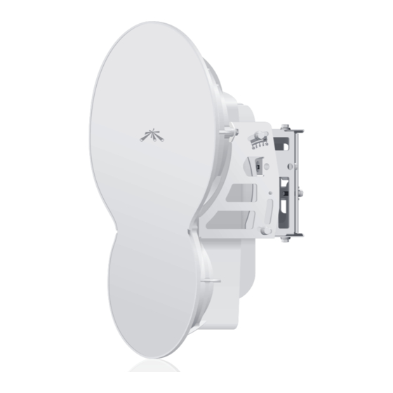
Ubiquiti airfiber AF24 Quick Start Manual
24 ghz point to point 1.4+ gbps radio
Hide thumbs
Also See for airfiber AF24:
- User manual (50 pages) ,
- Quick start manual (37 pages) ,
- Quick start manual (37 pages)
Table of Contents
Advertisement
Quick Links
Advertisement
Table of Contents

Related Manuals for Ubiquiti airfiber AF24


Summary of Contents for Ubiquiti airfiber AF24
- Page 1 24 GHz Point to Point 1.4+ Gbps Radio Model: AF24...
-
Page 3: Package Contents
Introduction Introduction Thank you for purchasing the Ubiquiti Networks airFiber 24 GHz ™ ™ Point-to-Point Radio, model AF24. This Quick Start Guide is designed to guide you through the installation of the airFiber AF24, show you how to access the airFiber Configuration Interface, and explain how to set up an airFiber link. -
Page 4: Hardware Overview
airFiber AF24 Quick Start Guide ™ Hardware Overview Side Lock Bolts Alignment Bracket Elevation Adjustment Azimuth Adjustment Lock Bolts Ground Bonding Point... - Page 5 Hardware Overview Back Lock Bolts Lock Bolts Elevation Adjustment Azimuth Adjustment Lock Bolts Lock Bolts Port Cover Cover Lock...
- Page 6 airFiber AF24 Quick Start Guide ™ Interfaces RESET DATA LED Display CONFIG Interface Description To reset to factory defaults, press and hold the RESET RESET button for more than five seconds while the unit is already powered on. DATA 10/100/1000 Mbps port handles all user traffic. Port for audio tone aiming.
- Page 7 Hardware Overview State Status 10/100 Mbps Speed 1000 Mbps No Ethernet Link Link/Act Ethernet Link Established Random Flashing Ethernet Activity No GPS Synchronization Operational (Strong Signal) Normal Flash* Operational (Weak Signal) ¼x or 1x (QPSK SISO) Short Flash* 2x (QPSK MIMO) Modulation Normal Flash* 4x (16QAM MIMO)
-
Page 8: Installation Requirements
(up to 100 m). We recommend that you protect your networks from the most brutal environments and devastating ESD attacks with industrial-grade shielded Ethernet cable from Ubiquiti Networks. For more details, visit www.ubnt.com/toughcable Installation Overview We recommend that you configure your paired airFiber radios before mounting. -
Page 9: Connecting Power Over Ethernet
Connecting Power over Ethernet • Once configuration is complete, disconnect the cables to move the airFiber radios. • Reconnect at the site. • After you have mounted the airFiber radios, establish and optimize the RF link. Connecting Power over Ethernet 1. - Page 10 airFiber AF24 Quick Start Guide ™ 3. Connect the other end of the Ethernet cable from the DATA port to the Ethernet port labeled POE on the PoE Adapter. 4. Connect the Power Cord to the power port on the PoE Adapter. Connect the other end of the Power Cord to a power source.
-
Page 11: Airfiber Configuration
The instructions in this section explain how to access the airFiber Configuration Interface and configure the following settings: • Wireless Mode Configure one airFiber AF24 as the Master and the other as the Slave. • Duplex The airFiber AF24 supports both half-duplex and full-duplex operation. - Page 12 AF24 Quick Start Guide ™ 1. Connect an Ethernet cable from your computer to the CONFIG port on the airFiber AF24. 2. Configure the Ethernet adapter on your computer with a static IP address on the 192.168.1.x subnet (for example, 192.168.1.100).
- Page 13 Configuration 5. Click the Wireless tab. 6. Enter the Basic Wireless Settings: a. For one airFiber AF24, select Master from the Wireless Mode drop-down. For the other airFiber AF24, keep the default, Slave. b. Enter a name in the Link Name field. This should be the same on both the Master and the Slave.
- Page 14 airFiber AF24 Quick Start Guide ™ 7. Configure the Wireless Security: a. Select the AES Key Type, HEX or ASCII. b. For the Key field: Enter 16 bytes (eight, 16-bit HEX values: 0-9, A-F, or a-f ). You can omit zeroes and use colons, similar to the IPv6 format.
-
Page 15: Hardware Installation
Ø 2.0" - 4.0" pole. a. Orient the Pole Mount Bracket around the pole so it is aimed in the direction of the other airFiber AF24. b. Insert the M10x150 Carriage Bolts into the Pole Clamps. c. Secure the clamps with the M10 Flat Washers, Split Lock Washers, and Hex Nuts. - Page 16 airFiber AF24 Quick Start Guide ™ 3. Loosen, but do NOT remove the eight Lock Bolts located on the Alignment Bracket. 4. Ensure that there is a 6 mm gap between the head of each M8x14 Serrated Flange Screw and the Alignment Bracket. 6 mm...
- Page 17 Hardware Installation 5. Lift the airFiber AF24 and align the four M8x14 Serrated Flange Screws with the slots on the Pole Mount Bracket. Seat the screws in the slots. Securely tighten the screws. WARNING: To prevent injury, ensure that all four screws...
- Page 18 airFiber AF24 Quick Start Guide ™ 6. Attach a ground wire: a. Remove the nut from the Ground Bonding Point. b. Attach a ground wire (min. 8 AWG or 10 mm ) to the lug and replace the nut to secure the wire. c.
-
Page 19: Connecting Ethernet
Connecting Ethernet Connecting Ethernet 1. Turn the Cover Lock to the Unlocked icon. Slide the Port Cover down to remove it. 2. Connect a TOUGHCable or other outdoor, shielded CAT5e/6 cable to the DATA port. 3. Create a strain relief for the Ethernet cable by feeding a Cable Tie through the tie slot under the cable. - Page 20 airFiber AF24 Quick Start Guide ™ 4. Connect the other end of the Ethernet cable from the DATA port to the Ethernet port labeled POE on the PoE Adapter. 5. Connect an Ethernet cable from your network to the Ethernet port labeled LAN on the PoE Adapter.
- Page 21 Connecting Ethernet Below is a diagram of a finished installation with recommended surge protectors installed. Ground to Pole, Tower, or Grounding Block (Max. 1 m from Ground Bonding Point) Max. 1 m Outdoor GigE PoE Surge Protector GigE Router or Switch Outdoor GigE PoE Surge Protector GigE PoE Adapter...
- Page 22 airFiber AF24 Quick Start Guide ™ Alignment Tips • We recommend using a pair of installers in constant communication because in the fine-tuning stage, one installer makes azimuth and elevation adjustments on one airFiber radio while the other installer reports the received signal level at the other airFiber radio.
- Page 23 Alignment 2. For the Master and Slave, ensure the Azimuth (AZ) and Elevation (EL) Adjustment Bolts are in the middle of their adjustment ranges. Elevation (EL) Adjustment Bolt Azimuth (AZ) Adjustment Bolt Master Aim the Master at the Slave. If necessary, adjust the Master's position on the pole: a.
- Page 24 Sweep the Elevation (EL) Adjustment Bolt of the Master through its adjustment range. Master Elevation (EL) Adjustment Bolt Master RF Power (-dBm) Note: If the LED Display indicates an overload condition , refer to the airFiber AF24 User Guide at: documentation.ubnt.com for more information.
- Page 25 4. Lock the alignment on both airFiber radios by tightening all eight Lock Bolts on the Alignment Bracket. 5. Observe the LED Display of each airFiber AF24 to ensure that the value remains constant while tightening the Lock Bolts. If...
-
Page 26: Installer Compliance Responsibility
• LED Display (described above) • airFiber Configuration Interface • Audio tone (optional equipment required) Refer to the airFiber AF24 User Guide for instructions on the airFiber Configuration Interface and audio tone methods. The User Guide is available at: documentation.ubnt.com... -
Page 27: Specifications
Specifications Specifications airFiber AF24 Dimensions 649 x 426 x 303 mm Weight 10.5 kg (Mount Included) Operating Frequency 24.05 – 24.25 GHz Max Power Consumption < 50 W Power Supply 50V, 1.2A PoE GigE Adapter (Included) Power Method Passive Power over Ethernet (42-58VDC) -
Page 28: Electrical Safety Information
Products furnished hereunder shall be free from defects in material and workmanship for a period of one (1) year from the date of shipment by UBIQUITI NETWORKS under normal use and operation. UBIQUITI NETWORKS sole and exclusive obligation under the foregoing warranty shall be to repair or replace, at its option, any defective Product that fails during the warranty period. - Page 29 Buyer for breach of warranty and shall constitute fulfillment of all liabilities of UBIQUITI NETWORKS with respect to the quality and performance of the Products. UBIQUITI NETWORKS reserves the right to inspect all defective Products (which must be returned by Buyer to UBIQUITI NETWORKS factory freight prepaid).
-
Page 30: Warranty Conditions
(IV) All Ethernet cabling runs use CAT5 (or above) shielded cabling. Disclaimer: UBIQUITI NETWORKS does not warrant that the operation of the products is error-free or that operation will be uninterrupted. In no event shall UBIQUITI NETWORKS be responsible for damages or claims of any nature or description relating to system performance, including coverage, buyer’s selection of products for buyer’s application and/or... - Page 31 Compliance Compliance Changes or modifications not expressly approved by the party responsible for compliance could void the user’s authority to operate the equipment. This device complies with Part 15 of the FCC Rules. Operation is subject to the following two conditions: 1.
-
Page 32: Rf Exposure Warning
airFiber AF24 Quick Start Guide ™ Cet appareil numérique de la classe A est confrome à la norme NMB-003 Canada. Pour réduire le risque d’interférence aux autres utilisateurs, le type d’antenne et son gain doivent être choisies de façon que la puissance isotrope rayonnée équivalente (PIRE) ne dépasse pas ce qui est nécessaire pour une communication réussie. -
Page 33: Declaration Of Conformity
UBIQUITI NETWORKS device, megfelel a vonatkozó alapvetõ [Hungarian] követelményeknek és az 1999/5/EC irányelv egyéb elõírásainak. Íslenska Hér me l sir UBIQUITI NETWORKS yfir ví a UBIQUITI NETWORKS device, er í samræmi vi grunnkröfur og a rar kröfur, sem ger ar eru í [Icelandic] tilskipun 1999/5/EC. - Page 34 [Swedish] egenskapskrav och övriga relevanta bestämmelser som framgår av direktiv 1999/5/EG. Español Por medio de la presente UBIQUITI NETWORKS declara que el UBIQUITI NETWORKS device, cumple con los requisitos esenciales [Spanish] y cualesquiera otras disposiciones aplicables o exigibles de la Directiva 1999/5/CE.
- Page 36 Support support.ubnt.com Wiki Page wiki.ubnt.com Support Forum forum.ubnt.com Downloads downloads.ubnt.com w w w . u b n t . c o m © 2012-2013 Ubiquiti Networks, Inc. All rights reserved.
Need help?
Do you have a question about the airfiber AF24 and is the answer not in the manual?
Questions and answers