Yamaha RX-497 Service Manual
Hide thumbs
Also See for RX-497:
- Owner's manual (326 pages) ,
- Owner's manual (56 pages) ,
- Owner's manual (53 pages)
Table of Contents
Advertisement
This manual has been provided for the use of authorized YAMAHA Retailers and their service personnel.
It has been assumed that basic service procedures inherent to the industry, and more specifically YAMAHA Products, are already
known and understood by the users, and have therefore not been restated.
WARNING:
IMPORTANT:
The data provided is believed to be accurate and applicable to the unit(s) indicated on the cover. The research, engineering, and service
departments of YAMAHA are continually striving to improve YAMAHA products. Modifications are, therefore, inevitable and
specifications are subject to change without notice or obligation to retrofit. Should any discrepancy appear to exist, please contact the
distributor's Service Division.
WARNING:
IMPORTANT:
CONTENTS
TO SERVICE PERSONNEL . . . . . . . . . . . . . . . . . . . . 2
IMPEDANCE SELECTOR . . . . . . . . . . . . . . . . . . . . . . 3
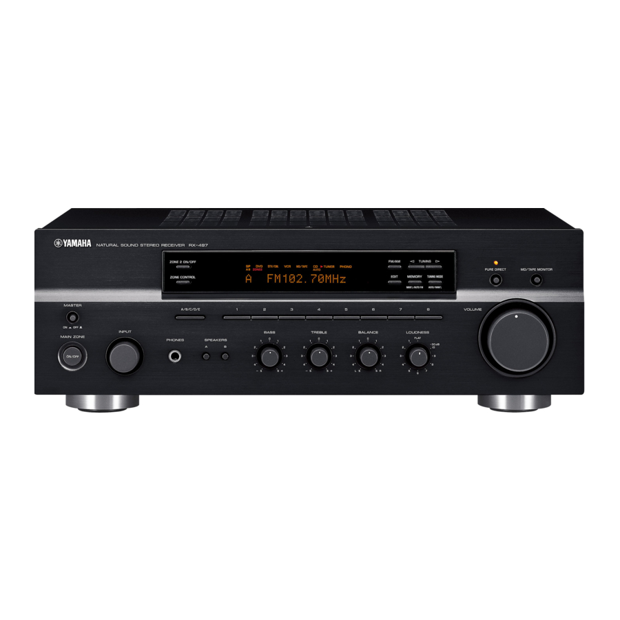
FRONT PANELS . . . . . . . . . . . . . . . . . . . . . . . . . . . . . 3
REAR PANELS . . . . . . . . . . . . . . . . . . . . . . . . . . . . 4-5
REMOTE CONTROL PANELS . . . . . . . . . . . . . . . . . . 5
SPECIFICATIONS . . . . . . . . . . . . . . . . . . . . . . . . . . 6-7
INTERNAL VIEW . . . . . . . . . . . . . . . . . . . . . . . . . . . . . 7
DISASSEMBLY PROCEDURES . . . . . . . . . . . . . . . . . 8
SELF DIAGNOSIS FUNCTION . . . . . . . . . . . . . . . 9-15
© 2005 YAMAHA CORPORATION. All rights reseved.
1 0 0 9 7 7
This manual is copyrighted by YAMAHA and may not be copied or
redistributed either in print or electronically without permission.
STEREO RECEIVER
RX-497
IMPORTANT NOTICE
Failure to follow appropriate service and safety procedures when servicing this product may result in personal
injury, destruction of expensive components, and failure of the product to perform as specified. For these reasons,
we advise all YAMAHA product owners that any service required should be performed by an authorized YAMAHA
Retailer or the appointed service representative.
The presentation or sale of this manual to any individual or firm does not constitute authorization, certification or
recognition of any applicable technical capabilities, or establish a principle-agent relationship of any form.
Static discharges can destroy expensive components. Discharge any static electricity your body may have
accumulated by grounding yourself to the ground buss in the unit (heavy gauge black wires connect to this buss).
Turn the unit OFF during disassembly and part replacement. Recheck all work before you apply power to the unit.
AMP ADJUSTMENT . . . . . . . . . . . . . . . . . . . . . . . . . 16
IC DATA . . . . . . . . . . . . . . . . . . . . . . . . . . . . . . . . 17-18
DISPLAY DATA . . . . . . . . . . . . . . . . . . . . . . . . . . . . . 19
PIN CONNECTION DIAGRAM . . . . . . . . . . . . . . . . . 20
PRINTED CIRCUIT BOARD . . . . . . . . . . . . . . . . 21-27
BLOCK DIAGRAM . . . . . . . . . . . . . . . . . . . . . . . . . . . 28
SCHEMATIC DIAGRAM . . . . . . . . . . . . . . . . . . . 29-32
PARTS LIST . . . . . . . . . . . . . . . . . . . . . . . . . . . . . 33-43
REMOTE CONTROL RAX100/RAX101 . . . . . . . 44-45
SERVICE MANUAL
SERVICE MANUAL
'05.11
Advertisement
Table of Contents

Related Manuals for Yamaha RX-497


Summary of Contents for Yamaha RX-497
-
Page 1: Table Of Contents
This manual has been provided for the use of authorized YAMAHA Retailers and their service personnel. It has been assumed that basic service procedures inherent to the industry, and more specifically YAMAHA Products, are already known and understood by the users, and have therefore not been restated. -
Page 2: To Service Personnel
RX-497 TO SERVICE PERSONNEL AC LEAKAGE 1. Critical Components Information EQUIPMENT WALL TESTER OR Components having special characteristics are marked Z OUTLET UNDER TEST EQUIVALENT and must be replaced with parts having specifications equal to those originally installed. 2. Leakage Current Measurement (For 120V Models Only) -
Page 3: Impedance Selector
RX-497 IMPEDANCE SELECTOR WARNING: Do not change the setting of the IMPEDANCE SELECTOR switch when the unit power is switched on, as doing so may damage the unit. IMPEDANCE SELECTOR FRONT PANELS U, C models R, A, G, E, L models... -
Page 4: Rear Panels
RX-497 REAR PANELS U, C models R model A model... -
Page 5: Remote Control Panels
RX-497 G, E models L model REMOTE CONTROL PANELS RAX100 (U, C models) RAX101 (R, A, G, E, L models) -
Page 6: Specifications
RX-497 SPECIFICATIONS AUDIO SECTION FM SECTION Minimum RMS Output Power (Power Amp. Section) Tuning Range L/R, 20 Hz to 20 kHz, 0.04% THD, 8 ohms ..75 W + 75 W U, C models ......87.5 to 107.9 MHz R, L models . -
Page 7: Internal View
RX-497 DIMENSIONS © 2005 XM Satellite Radio Inc. All rights reserved. All other trademarks are the property of their respective owners. U ..USA model G ..European model C ..Canadian model E ..South European model R ..General model L .. -
Page 8: Disassembly Procedures
RX-497 DISASSEMBLY PROCEDURES • Remove parts in disassembly order as numbered. • Disconnect the power cable from the AC outlet. 1. Removal of Top Cover 4. Removal of Sub Chassis Unit a. Remove 4 screws ( ), 1 screw ( ) and 4 screws a. -
Page 9: Self Diagnosis Function
RX-497 SELF DIAGNOSIS FUNCTION This product has a built-in self diagnosis function (DIAG) to facilitate inspection, measurement and determination of a faulty item, if any. There are 8 DIAG menu items, each having sub-menu items. No. DIAG menu Sub-menu DISPLAY CHECK 1. - Page 10 RX-497 Starting DIAG Display provided when DIAG started Press the “MASTER” key of the main unit while simulta- On the FL display of the main unit, an opening mes- neously pressing the “FM/AM” key and the “8” key to acti- sage (including the version and the protection history) vate the DIAG function.
- Page 11 RX-497 Operation procedure of DIAG MENU and The protection function worked due to a DC voltage ap- pearing at the speaker terminal. SUB-MENU A cause could be a defect in the amplifier. If the power is There are 8 MENU items, each of which has some SUB- turned on with the abnormality unsolved, the protection func- MENU items.
- Page 12 RX-497 1. DISPLAY CHECK 2. FACTORY PRESET This program is used to check the FL display section. The This menu is used to reserve/inhibit initialization of the back- display condition varies as shown below according to the up RAM. sub-menu operation.
- Page 13 R, A, G, E, L 87.5 87.50 500% display of the voltage based on the temperature de- 90.1 90.10 tected value. Reference voltage: 5V 95.1 95.10 * For RX-497, only R ch is effective. A/C/E 98.1 98.10 107.9 108.00 88.1 88.10 THM:L000 R098 106.1...
- Page 14 RX-497 5. PROTECTION SETTING 6. PROTECTION HISTORY This menu is used to change the protection setting value. Four protection histories are display. The change is effective in this menu only. A set value can The history is cleared by the initialization reservation of DIAG be specified between 0 –...
- Page 15 RX-497 7. SOFT SWITCH 8. MICROPROCESSOR INFORMATION The version, checksum and the port specified by the Note) Changing the function setting may hinder the proper microprocessor are displayed. The checksum is obtained operation. by adding the data at every 16 bits for each program area and expressing the result as a 4-figure hexadecimal This menu is used to switch the function settings on P.C.B.
-
Page 16: Amp Adjustment
RX-497 AMP ADJUSTMENT CONFIRMATION OF IDLING CURRENT 1. Right after the power is turned on, confirm that the volt- age across the terminals of R137 (L ch) and R138 (R ch) are between 0.1mV to 10.0mV. 2. If the measured voltage exceeds 10.0mV, open (cut off) R131 (L ch), R132 (R ch) and reconfirm the voltage. -
Page 17: Ic Data
RX-497 IC DATA IC602 : M30626FHPFP (FUNCTION (2) P.C.B.) 16-bit Microprocessor P07/D7 P44/CS0 P06/D6 P45/CS1 P05/D5 P46/CS2 P04/D4 P47/CS3 P03/D3 P50/WRL/WR P02/D2 P51/WRH/BHE P01/D1 P52/RD P00/D0 P53/BCLK P107/AN7/K13 P54/HLDA P106/AN6/K12 P55/HOLD P105/AN5/K11 P56/ALE P104/AN4/K10 P57/RDY/CLKOUT P103/AN3 P60/CTS0/RTS0 P102/AN2 P61/CLK0 P101/AN1... - Page 18 RX-497 IC602 : M30626FHPFP (FUNCTION (2) P.C.B.) 16-bit Microprocessor Port Name Function P64/CTS1/RTS1/CTS0/CLKS1 AF220 BUSY Signal Output P63/TXD0/SDA0 DTIS Input Selector Tx DATA P62/RXD0/SCL0 CEIS Input Selector CE P61/CLK0 CKIS Input Selector CLOCK P60/CTS0/RTS0 DTRZ Rec/Zone2 selecter DATA P57/RDY/CLKout CKRZ Rec/Zone2 selecter CLOCK N.C.
-
Page 19: Display Data
RX-497 DISPLAY DATA V801 : 15-BT-105GNK (WF519900) PATTERN AREA PIN CONNECTION Note 1) F1, F2 ..Filament 2) NP ....No Pin 3) NX ....No Extend Pin 4) P1~P35 ..Datum Line 5) 1G~15G ..Grid GRID ASSIGNMENT ANODE CONNECTION... -
Page 20: Pin Connection Diagram
RX-497 PIN CONNECTION DIAGRAM µPC29M33T-E1 LM61CIZ NJU7201L55 NJM7805FA PQ05RD11 TLP421 TC4013BP 1: VIN 1: INPUT 1: OUTPUT 2: VO 2: GND 2: COMMON 3: GND 3: OUTPUT 3: GND 3: GND 3: INPUT 4: VC 4: GND 2: Vout 2: VIN... - Page 21 RX-497 PRINTED CIRCUIT BOARD FUNCTION (1) P.C.B. FUNCTION (3) P.C.B. (Side A) FUNCTION (2) FUNCTION (2) (Side A) CB603 CB602 OUTPUT ZONE2 DTV/CBL (REC) MD/TAPE (PLAY) (REC) MONITOR (PLAY) DTV/CBL FUNCTION (1) Circuit No. U, C R, L G, E...
- Page 22 RX-497 PRINTED CIRCUIT BOARD FUNCTION (2) P.C.B. (Side A) OPERATION (13) CB301 OPERATION (1) OPERATION (2) TUNER PACK CB801 CB401 CB24 (U, C models) FUNCTION (2) Circuit No. U, C R, L G, E CB604 R679, 681, 683, 686 R687, 688...
- Page 23 RX-497 PRINTED CIRCUIT BOARD FUNCTION (4) P.C.B. OPERATION (1) P.C.B. (Side A) (Side A) OPERATION (10) CB810 A/B/C/D/E OPERATION (7) CB815 REMOTE OPERATION (6) CB811 TUNING ZONE CONTROL EDIT MEMORY MODE WOOFER FM/AM TUNING ZONE2 ON/OFF FUNCTION (1) W505 OPERATION (5)
- Page 24 RX-497 PRINTED CIRCUIT BOARD OPERATION (2) P.C.B. OPERATION (3) P.C.B. (Side A) (Side A) FUNCTION (2) FUNCTION (2) FUNCTION (1) CB611 W601 CB505 OPERATION (2) W405 LOUDNESS BALANCE TREBLE BASS OPERATION (3) P.C.B. (Side B) Lead Free Solder Used MAIN (1)
- Page 25 RX-497 PRINTED CIRCUIT BOARD OPERATION (5) P.C.B. OPERATION (7) P.C.B. OPERATION (8) P.C.B. OPERATION (9) P.C.B. (Side A) (Side A) (Side A) (Side A) OPEARTION (1) OPERATION (1) CB807 OPERATION (2) W806 CB403 PURE DIRECT SPEAKERS INPUT MAIN ZONE OPERATION (7) P.C.B.
-
Page 26: Printed Circuit Board
RX-497 PRINTED CIRCUIT BOARD Lead Free Solder Used MAIN (1) P.C.B. MAIN (5) P.C.B. MAIN (3) P.C.B. (Side A) (Side A) (Side A) MAIN (1) Circuit No. A, G, E, L U, C, R C156–159, 161, 162 X: NOT USED... - Page 27 RX-497 PRINTED CIRCUIT BOARD Lead Free Solder Used MAIN (2) MAIN (2) P.C.B. XM P.C.B. (Side A) Lead Free Solder Used Circuit No. U, C G, E J252 Point e (Pin 28 of IC1) POWER CABLE (Side A) CB253, 254...
-
Page 28: Block Diagram
RX-497 BLOCK DIAGRAM • See page 32 → SCHEMATIC DIAGRAM U, C models IC26 XMDT AK4384ET 11,10 2ch DAC IC25 OPERATION RY103 • See page 30 → SCHEMATIC DIAGRAM C834,835 Head Phone FM/AM IC401 12,19 RY101 TUNER Motor Volume Muting... - Page 29 RX-497 IC451: LA7956 SCHEMATIC DIAGRAM (FUNCTION) Video Switch 6 dB 4-INPUT 1-OUTPUT CONTROL VIDEO SWITCH DRIVER VIDEO VIN1 VIN2 VIN3 VIN4 11.8 IC501: NJU7313AM Analog Function Switch 11.9 14.2 12.4 14.1 14.1 12.4 L-COM1 R-COM1 L-COM2 R-COM2 L-COM3 R-COM3 DATA...
- Page 30 RX-497 SCHEMATIC DIAGRAM (OPERATION) IC301, 401, 751: NJM2068MD-TE Dual OP-Amp 14.7 13.3 13.3 –IN – – –IN –V PURE DIRECT OFF -14.3 14.2 -14.3 PURE DIRECT OFF PURE DIRECT ON -13.9 12.8 IC431: LB1641 Motor Driver IC801: M66003-0131FP Display Driver...
- Page 31 RX-497 SCHEMATIC DIAGRAM (MAIN) IC102 : LM61CIZ Temperature Sensor Vout Page 30 TO POWER TRANSFORMER TO OPERATION (1) W801 Page 29 TO FUNCTION (2) CB605 29.3 29.3 29.3 29.3 -0.4 15.3 35.9 36.0 15.3 36.0 14.7 29.3 51.0 Point w 15.3...
- Page 32 RX-497 SCHEMATIC DIAGRAM (XM) -7.1 AC9.2 11.0 11.0 TO POWER TRANSFORMER IC24 : SN74LV245APWR IC25 : AK4384ET Octal 3-State Bus Transceivers D/A Convertter 20 V MCLK 19 ENG Point e (Pin 28 of IC1) 18 B1 IC26 : NE5532DR IC27 : PQ05RD11...
-
Page 33: Parts List
RX-497 PARTS LIST WARNING ELECTRICAL PARTS Components having special characteristics are marked Z and must be replaced with parts having specifications equal to those originally installed. ABBREVIATIONS IN THIS LIST ARE AS FOLLOWS : C.A.EL.CHP : CHIP ALUMI. ELECTROLYTIC CAP L.EMIT... - Page 34 RX-497 P.C.B. FUNCTION...
- Page 35 RX-497 P.C.B. FUNCTION & OPERATION...
- Page 36 RX-497 P.C.B. OPERATION & MAIN...
- Page 37 RX-497 P.C.B. MAIN...
- Page 38 RX-497 P.C.B. XM & CHIP RESISTORS NOTE The chip resistor is not supplied as a replacement part. When a chip resistor is necessary, use the following part. AAX60720: CHIP RESISTOR SAMPLE BOOK...
- Page 39 RX-497 Parts List for Carbon Resistors Value 1/4W Type Part No. 1/6W Type Part No. Value 1/4W Type Part No. 1/6W Type Part No. 1.0 Ω 3100 3100 7100 10 kΩ 7100 HJ35 HF85 HF45 HF45 1.8 Ω 3180 7110 11 kΩ...
-
Page 40: Exploded View
RX-497 EXPLODED VIEW 200-1 7 (6) 2-122 2-120 7 (5) 2-60 7 (3) 7 (1) 7 (10) 2-122 2-122 2-121 2-50 7 (7) 2-120 2-120 7 (8) 2-30 7 (2) 2-20 2-20 2-120 2-70 2-30 2-121 2-40 7 (9) 7 (4) - Page 41 RX-497 MECHANICAL PARTS...
- Page 42 RX-497...
- Page 43 RX-497...
-
Page 44: Remote Control Rax100/Rax101
RX-497 REMOTE CONTROL TRANSMITTER (RAX100/RAX101) SCHEMATIC DIAGRAM P0D2 P1A2 3.0V 47 F 220 F OPEN P0D3 P0D1 P1B/INT P0D0 P0E0 P0C3 P0E1 P0C2 2 (1/4W) P0E2 P0C1 SID303C-01 P0E3 P0C0 SLEEP 6CH INPUT VOLUME - MENU P0B3 TUNER AUDIO VOLUME +... - Page 45 RX-497 DATA CODE LIST CODE Function COMMON TAPE CD-R TUNER TV POWER AV POWER 7F-80 7C-80 STANDBY 7E-7F SYSTEM POWER 7E-7E 7A-15 MD/TAPE 7A-18 TUNER 7A-16 7A-B4 7A-C1 DTV/CBL 7A-54 7A-0F PHONO 7A-14 REC/DISC SKIP 7A-4F 7A-04 79-AF 7C-8B PAUSE...
- Page 46 RX-497...
Need help?
Do you have a question about the RX-497 and is the answer not in the manual?
Questions and answers