Advertisement
Table of Contents
- 1 Table of Contents
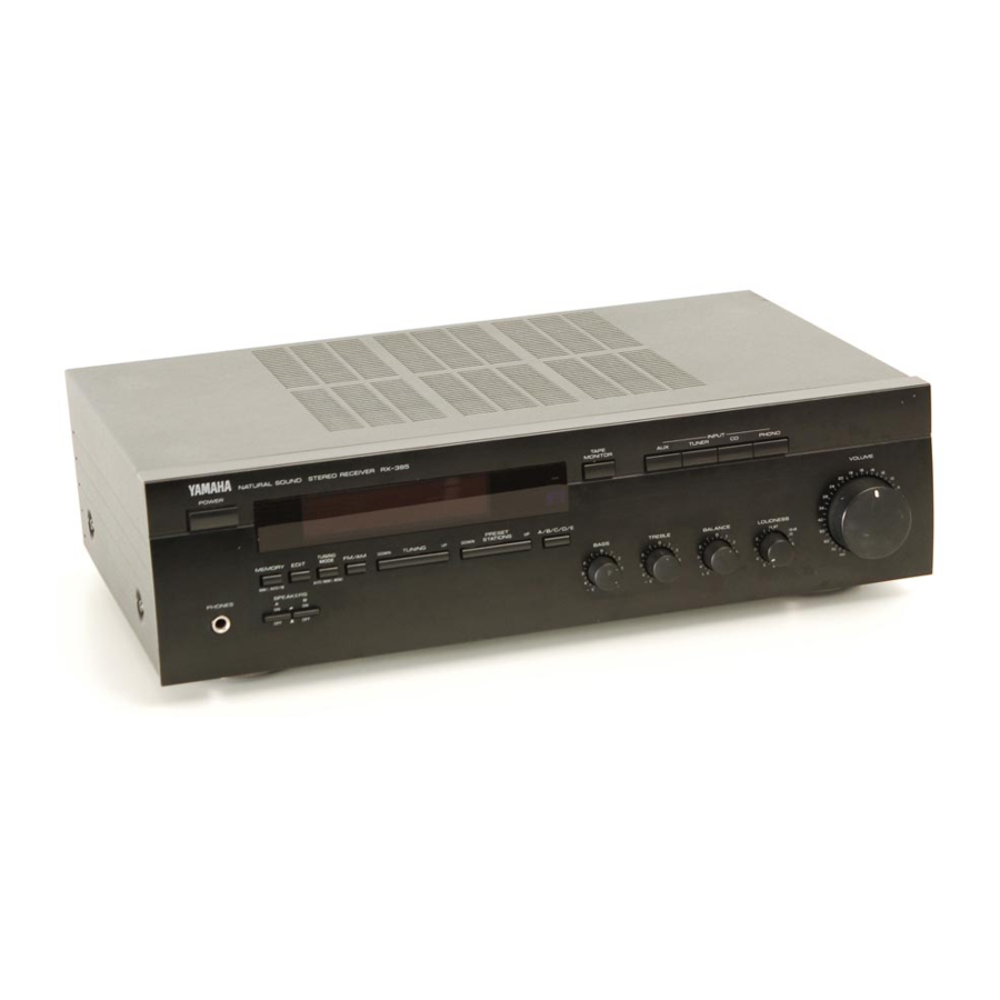
- 2 Natural Sound Stereo Receiver
- 3 Safety Instructions
- 4 Supplied Accessories
- 5 Connections
- 6 Operations
- 7 Selecting the Speaker System
- 8 Tuning Operations
- 9 Preset Tuning
- 10 Exchanging Preset Stations
- 11 Remote Control Transmitter
- 12 Notes about the Remote Control Transmitter
- 13 Troubleshooting
- 14 Specifications
- Download this manual
65W + 65W (8Ω) RMS Output Power, 0.04% THD, 20 - 20,000 Hz (RX-485)
45W + 45W (8Ω) RMS Output Power, 0.04% THD, 20 - 20,000 Hz (RX-385)
High Dynamic Power, Low Impedance Drive Capability
Pure Direct Switch to Reproduce the Purest Source Sound (RX-485 Only)
Thank you for selecting this YAMAHA stereo receiver.
OWNER'S MANUAL
CONTENTS
Safety Instructions ...................2
Supplied Accessories ..............4
Connections.............................5
Operations ...............................9
Tuning Operations ..................12
Preset Tuning .........................13
Control Transmitter ................17
Troubleshooting ......................18
Specifications .........................19
RX -485/385
Continuously Variable Loudness Control
IF Count Direct PLL Synthesizer Tuning System
IMPORTANT!
Please record the serial number of this
unit in the space below.
Model:
Serial No.:
The serial number is located on the rear
of the unit.
Retain this Owner's Manual in a safe
place for future reference.
WARNING
TO REDUCE THE RISK OF FIRE OR
ELECTRIC SHOCK, DO NOT EXPOSE
THIS UNIT TO RAIN OR MOISTURE.
Natural Sound Stereo Receiver
40-Station Random Preset Tuning
Automatic Preset Tuning
Preset Station Shifting Capability
Remote Control Capability
CAUTION
RISK OF ELECTRIC SHOCK
DO NOT OPEN
CAUTION: TO REDUCE THE RISK OF
ELECTRIC SHOCK, DO NOT REMOVE
COVER (OR BACK), NO USER-SERVICEABLE
PARTS INSIDE, REFER SERVICING TO
QUALIFIED SERVICE PERSONNEL.
• Explanation of Graphical Symbols
The lightning flash with arrowhead
symbol, within an equilateral triangle,
is intended to alert you to the
presence of uninsulated "dangerous
voltage" within the product's
enclosure that may be of sufficient
magnitude to constitute a risk of
electric shock to persons.
The exclamation point within an
equilateral triangle is intended to alert
you to the presence of important
operating and maintenance
(servicing) instructions in the
literature accompanying the
appliance.
Advertisement
Table of Contents

Related Manuals for Yamaha RX-485


Summary of Contents for Yamaha RX-485
-
Page 1: Table Of Contents
65W + 65W (8Ω) RMS Output Power, 0.04% THD, 20 – 20,000 Hz (RX-485) 45W + 45W (8Ω) RMS Output Power, 0.04% THD, 20 – 20,000 Hz (RX-385) High Dynamic Power, Low Impedance Drive Capability IF Count Direct PLL Synthesizer Tuning System Pure Direct Switch to Reproduce the Purest Source Sound (RX-485 Only) Thank you for selecting this YAMAHA stereo receiver. -
Page 2: Safety Instructions
SAFETY INSTRUCTIONS (U.S.A.) Read Instructions – All the safety and operating instructions should be read before the unit is operated. Retain Instructions – The safety and operating instructions should be retained for future reference. Heed Warnings – All warnings on the unit and in the operating instructions should be adhered to. - Page 3 This product, when installed as indicated in the instructions contained in this manual, meets FCC requirements. Modifications not expressly approved by Yamaha may void your authority, granted by the FCC, to use the product. 2. IMPORTANT : When connecting this product to accessories and/or another product use only high quality shielded cables.
-
Page 4: Supplied Accessories
L or coloured RED. Making sure that neither core is connected to the earth terminal of the three pin plug. SUPPLIED ACCESSORIES After unpacking, check that the following parts are contained. Indoor FM Antenna AM Loop Antenna Remote Control Transmitter RX-485 Batteries (size AA, R6, UM-3) RX-385... -
Page 5: Antenna Connections
ANTENNA CONNECTIONS Each antenna should be connected to the designated terminals correctly, referring to the following figure. Both AM and FM indoor antennas are included with this unit. In general, these antennas will probably provide sufficient signal strength. Nevertheless, a properly installed outdoor antenna will give clearer reception than an indoor one. If you experience poor reception quality, an outdoor antenna may result in improvement. -
Page 6: Audio Connections
When making connections between this unit and other components, be sure all connections are made correctly, that is to say L (left) to L, R (right) to R, “+” to “+” and “–” to “–”. Also, refer to the owner’s manual for each component to be connected to this unit. RX-485 Video cassette player etc. - Page 7 RX-385 Video cassette player etc. UNBAL TAPE 1 PHONO TAPE Turntable Compact disc player Speakers A Right SPEAKERS Right Tape deck Speakers B Left (U.S.A. model) AC OUTLETS SWITCHED 120V 50Hz 100W MAX TOTAL To AC outlet Left : Refer to “ABOUT THE ACCESSORY TERMINALS”...
-
Page 8: Connecting Speakers
Black: negative (–) REMOTE CONTROL (PHONO) connector RX-485 only If you have a YAMAHA turntable with a terminal for remote control, connect it to this connector by using the cable provided with the turntable. This connection allows you to control the... -
Page 9: Operations
PHONO LOUDNESS controls, etc. (Refer to page 11.) Notes RX-485 only If you select AUX, TUNER, CD or PHONO, be sure that TAPE 1 and/or TAPE 2 are not being selected. If you select TAPE 1 and TAPE 2 at the same time, the result will be the sound from the tape deck 1. - Page 10 TO RECORD A SOURCE TO TAPE RX-485 Select the source to be recorded. MONITOR TAPE 2 TAPE 1 TUNER COPY * To dub from tape to tape, refer to the “Notes” shown below. * When you select AUX, TUNER, CD or PHONO, be sure that TAPE 1 and/or TAPE 2 are not also selected.
-
Page 11: Selecting The Speaker System
Using the PURE DIRECT switch RX-485 only You can enjoy the purest possible sound from your audio sources by setting this switch ON. By doing so, the audio signal bypasses the BASS, TREBLE, BALANCE and LOUDNESS controls, eliminating any alterations to the audio signal. -
Page 12: Automatic Tuning
Normally, if station signals are strong and there is no interference, quick automatic-search tuning (AUTOMATIC TUNING) is possible. However, if signals of the station you want to select are weak, you must tune to it manually (MANUAL TUNING). AUTOMATIC TUNING Select the reception band (FM or AM) while watching the display. -
Page 13: Manual Preset Tuning
MANUAL PRESET TUNING This unit can store station frequencies selected by tuning operation. With this function, you can recall any desired station by only selecting the preset station number where it is stored. Up to 40 stations (8 stations x 5 pages) can be stored. 2, 5 To store stations Tune to a desired station. -
Page 14: Automatic Preset Tuning
AUTOMATIC PRESET TUNING You can also make use of an automatic preset tuning function for FM stations only. By this function, this unit performs automatic tuning and stores FM stations with strong signals sequentially. Up to 40 stations are stored automatically in the same way as in the manual preset tuning method on page 13. -
Page 15: Exchanging Preset Stations
EXCHANGING PRESET STATIONS You can exchange the places of two preset stations each other by easy operations. 2, 4 Example) If you want to shift the preset station on E1 to A5, and vice versa. Recall the preset station on E1 (by following the method of “To recall a preset station”... -
Page 16: Remote Control Transmitter
The remote control transmitter provided with this unit is designed to control all the most commonly used functions of the unit. If the CD player, turntable and tape deck connected to this unit are YAMAHA components, then this remote control transmitter will also control various functions of each component. -
Page 17: Notes About The Remote Control Transmitter
STANDBY mode (Europe model only) While the power is on, pressing the POWER key on the remote control transmitter switches the unit to the STANDBY mode. (In this mode, the standby indicator on the front panel is half illuminated.) NOTES ABOUT THE REMOTE CONTROL TRANSMITTER Battery installation Battery replacement If you find that the remote control transmitter must be used... -
Page 18: Troubleshooting
If the unit fails to operate normally, check the following points to determine whether the fault can be corrected by the simple measures suggested. If it cannot be corrected, or if the fault is not listed in the SYMPTOM column, disconnect the power cord and contact your authorized YAMAHA dealer or service center for help. SYMPTOM The unit fails to turn on when the POWER switch is pressed. -
Page 19: Specifications
SPECIFICATIONS AUDIO SECTION Minimum RMS Output Power per Channel 8 ohms, 20 Hz to 20 kHz, 0.04% THD < > RX-485 ...65W+65W < > RX-385 [U.S.A. and Canada models]...45W+45W [Australia, U.K., Europe and General models]...40W+40W 6 ohms, 20 Hz to 20 kHz, 0.06% THD <... - Page 20 YAMAHA ELECTRONICS (UK) LTD. YAMAHA HOUSE, 200 RICKMANSWORTH ROAD WATFORD, HERTS WD1 7JS, ENGLAND YAMAHA SCANDINAVIA A.B. J A WETTERGRENS GATA 1, BOX 30053, 400 43 VÄSTRA FRÖLUNDA, SWEDEN YAMAHA MUSIC AUSTRALIA PTY, LTD. 17-33 MARKET ST., SOUTH MELBOURNE, 3205 VIC., AUSTRALIA...
Need help?
Do you have a question about the RX-485 and is the answer not in the manual?
Questions and answers