Table of Contents
Advertisement
Operator's Manual
10 IN. PORTABLE TABLE SAW
Model No. 137.415030
CAUTION:
Before using this Table Saw,
read this manual and follow
all its Safety Rules and
Operating Instructions
Customer Help Line
For Technical Support
1-800-843-1682
Sears Brands Management Corporation Hoffman Estates, IL 60179 USA
See the full line of Craftsman
Click on the Craftsman Club
Part No. 137415030001
products at craftsman.com
®
link and join today!
®
1
Safety Instructions
●
●
●
●
●
Sears Parts &
Repair Center
1-888-331-4569
Printed in China
Advertisement
Table of Contents

Related Manuals for Craftsman 137.415030


Summary of Contents for Craftsman 137.415030
- Page 1 Sears Parts & For Technical Support Repair Center 1-800-843-1682 1-888-331-4569 Sears Brands Management Corporation Hoffman Estates, IL 60179 USA See the full line of Craftsman products at craftsman.com ® Click on the Craftsman Club link and join today! ® Part No. 137415030001...
- Page 2 For 90 DAY commercial and rental use terms, see the Craftsman warranty web page. This warranty gives you specific legal rights, and you may also have other rights which vary from state to state.
- Page 3 PRODUCT SPECIFICATIONS MOTOR Type................Universal Amperes............... 15 Amp Voltage................. 120 V AC Hz................. 60 Hz RPM (no load) ............. 5000 RPM (No load) Overload Protection............. Yes BLADE SIZE Diameter..............10 in. Arbor Size..............5/8 in. Rip Fence..............Yes Miter Gauge..............Yes Rip Capacity ..............
- Page 4 SYMBOLS WARNING ICONS Your power tool and its Operator’s Manual may contain “WARNING ICONS” (a picture symbol intended to alert you to, and/or instruct you how to avoid, a potentially hazardous condition). Understanding and heeding these symbols will help you operate your tool better and safer. Shown below are some of the symbols you may see.
- Page 5 POWER TOOL SAFETY 5. DO NOT USE IN DANGEROUS GENERAL SAFETY INSTRUCTIONS ENVIRONMENTS. Do not use BEFORE USING THIS POWER TOOL power tools in damp locations, or Safety is a combination of common expose them to rain or snow. Keep sense, staying alert and knowing how work area well lit.
- Page 6 11. WEAR PROPER APPAREL. Do 16. REDUCE THE RISK OF not wear loose clothing, gloves, UNINTENTIONAL STARTING. neckties, rings, bracelets or other Make sure switch is in the OFF jewelry which may get caught in position before plugging the tool in. moving parts.
- Page 7 21. DO NOT OVERREACH. Keep proper footing and balance at all times. NEVER reach across the path of the cutting blade while tool is in operation. 22. MAINTAIN TOOLS WITH CARE. Keep tools sharp and clean for best and safest performance. Follow instructions for lubricating and changing accessories.
- Page 8 TABLE SAW SAFETY 1. ALWAYS USE SAW BLADE 6. NEVER REACH behind or over the GUARD, riving knife and anti- cutting tool for any reason. kickback pawls assembly for every through–sawing operation. Through 7. REMOVE the rip fence when –sawing operations are those in crosscutting.
- Page 9 14.AVOID AWKWARD OPERATIONS 20.For proper operation follow the and hand positions where a sudden instructions in this Instruction Manual entitled ASSEMBLY AND slip could cause your hand to move into the saw blade. ADJUSTMENTS (Page 20). Failure to provide sawdust fall-through and 15.NEVER USE SOLVENTS to removal hole will allow sawdust clean plastic parts.
- Page 10 TABLE SAW SAFETY glasses, the means to avoid kickback SAW BLADE GUARD ASSEMBLY, and all other warnings contained in this ANTI-KICKBACK ASSEMBLY AND manual and on the saw itself. Replace RIVING KNIFE the guarding systems as soon as you Your table saw is equipped with a return to thru-cutting operations.
- Page 11 once it has started. Check their action before ripping by pushing the wood under the anti-kickback assembly. The teeth must prevent the wood from being pulled toward the front of the saw. d. Plastic and composite (like hardboard) materials may be cut on your saw.
- Page 12 ELECTRICAL REQUIREMENTS AND SAFETY IMPROPER CONNECTION of the POWER SUPPLY AND MOTOR equipment grounding conductor can SPECIFICATIONS result in risk of electric shock. The WARNING conductor with the green insulation (with or without yellow stripes) is the To avoid electrical hazards, fire equipment grounding conductor.
- Page 13 overheating and burning out of the The adapter (Fig. 2) has a grounding motor. The table below shows the lug extending from it that MUST be correct size to use depending on cord connected to a permanent earth length and nameplate ampere rating. If ground, such as a properly grounded in doubt, use the next heavier gauge.
- Page 14 SUPPLIED WARNING Flat bladed Visit your Sears Hardware Box-end screwdriver wrench Department or see the Craftsman Power and Hand Tools Catalog to purchase recommended Phillips screwdriver accessories for this power tool. 308K DADO INSERT PLATE Open-end wrench WARNING...
- Page 15 CARTON CONTENTS Separate all parts from packing WARNING materials. Check each part with the If any part is missing or damaged, illustration on the next page and the do not attempt to assemble the “Table of Loose Parts” to make certain table saw, plug in the power all items are accounted for, before cord, or turn the switch ON until...
- Page 16 UNPACKING YOUR TABLE SAW...
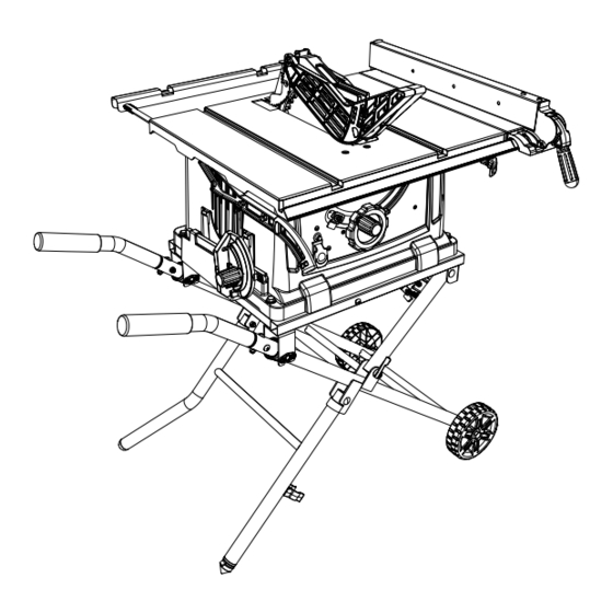
- Page 17 KNOW YOUR TABLE SAW Blade guard Rip fence Push stick storage Miter gauge storage Extension table locking lever Blade elevation/ Miter gauge tilting handwheel Overload reset switch Stand handle ON/OFF switch with safety key Locking hook Leveling foot Leg clamp Blade Riving knife Table insert...
- Page 18 GLOSSARY OF TERMS FREEHAND – Performing a cut without ANTI-KICKBACK PAWLS ASSEMBLY using a rip fence, miter gauge, hold – Prevents the workpiece from being down or other proper device to prevent kicked upward or back toward the front the workpiece from twisting during the of the table saw by the spinning blade.
- Page 19 SAW BLADE PATH – The area of the OVERLOAD RESET SWITCH – workpiece or table top directly in line Protects the motor if it overloads during with the travel of the blade or the part operation, provides a way to restart the of the workpiece that will be cut.
- Page 20 ASSEMBLY Fig. A WARNING For your safety, never connect plug to power source receptacle until all assembly and adjustment steps are complete, and you have read and understood the safety instructions. ASSEMBLING THE ROLLER WHEELS AND HANDLES TO STAND (FIG. A, B, C) 1.
- Page 21 5. Check to be sure the stand lock NOTE: Do not overtighten the four lever (5) is in the slot of the cover bolts as this may cause damage to plate (6). (Fig. D) the base of the saw. Fig. E Fig.
- Page 22 5. Fold the stand slowly downward as Fig. H shown in Fig. F. 6. Move the saw to the desired location for operation or store the saw in a dry environment by using the left side stand handles (10). Fig. F Transporting Push stick (Fig.
- Page 23 Fig. J INSTALLING THE REAR OUTFEED SUPPORT (FIG. L, M) 1. Insert the two rear outfeed support tubes (2) into the rear outfeed support (1). (Fig. L) NOTE: They must be inserted into the back of the extension with the dimple end so that the bar will hold the extension in place.
- Page 24 Fig. M 2. Remove the arbor nut (3) and outer blade flange (4). (Fig. O) Fig. O INSTALLING THE BLADE (FIG. N, O, P) WARNING 3. Place the blade (7) onto the arbor (5) with the blade teeth pointing forward To avoid injury from an accidental to the front of the saw.
- Page 25 Fig. P 3. Place the box-end wrench (9) on the arbor nut (3) and turn counterclockwise. (Fig. P) 4. Remove the arbor nut (3), outer blade flange (4) and blade (7). Clean but do not remove the inner blade flange before reassembling the blade.
- Page 26 5. Place the riving knife (3) on the Fig. R mounting bracket (4) located behind the saw blade. The two pins (5) on the bracket should fit into the slot on the riving knife. (Fig. Q) 6. Make sure the riving knife (3) is in its highest position.
- Page 27 3. Place the front of assembly into 7. Make sure that the assembly is slot (3) and push down, making locked in place both in front and sure the assembly is engaged in back. (Fig. V) the slots. Push down on the locking WARNING lever (2) to lock.
- Page 28 Removing the blade guard and anti- WARNING kickback pawls assembly (Fig. S, V) Improper riving knife alignment can WARNING cause “kickback” and serious injury. To avoid injury from an accidental Fig. W start, make sure the switch is in the OFF position and the plug is Anti-kickback Pawls disconnected from the power source outlet.
- Page 29 ADJUSTMENT RIP FENCE ADJUSTMENT (FIG. Y) WARNING 1. The fence (1) can be repositioned Failure to properly align the fence by lifting up the handle (2) and can cause “kickback” and serious sliding the fence to the desired injury could occur. location.
- Page 30 Fig. Z ADJUSTING THE TABLE INSERT (FIG. BB) WARNING To avoid serious injury, the table insert (1) must be level with the table. If the table insert is not flush with the table, adjust the two bolts (2) with a 4 mm hex wrench until it is parallel with the table.
- Page 31 3. Loosen the blade lock knob and 45° Stop move the blade to the maximum 1. Disconnect the saw from the power vertical position and tighten the source. blade lock knob. 2. Raise the blade to the maximum 4. Place a combination square on the elevation.
- Page 32 BLADE TILT POINTER (FIG. EE) 1. Remove the safety switch key and 1. When the blade is positioned at 90°, unplug the saw. adjust the blade tilt pointer (1) to 2. Remove the blade guard for this read 0° on the scale. procedure but reinstall and realign 2.
- Page 33 ADDITIONAL BLADE ADJUSTMENTS ALIGNING THE RIVING KNIFE (FIG. GG) (FIG. HH) NOTE: The adjusting mechanism is WARNING located above the the blade elevation/ ● To avoid injury from an accidental tilting handwheel under the table top. start, make sure the switch is in If the front and rear measurements are the OFF position and the plug not the same:...
- Page 34 a. Remove the lock lever (4), ● The tip of the riving knife shall not washer (5), set plate (6) and be lower than 0.04 in. ~ 0.2 in. riving knife (2) from the mounting from the tooth peak. bracket (7). ●...
- Page 35 OPERATION BASIC SAW OPERATIONS WARNING ALWAYS lock the switch “OFF” RAISING THE BLADE (FIG. JJ) when the saw is not in use. Remove To raise or lower the blade, turn the the safety switch key and keep it in blade elevation/tilting handwheel (1) to a safe place.
- Page 36 undersized extensing cord. Inspect Fig. MM your saw for proper setup before using it again. USING THE DUST PORT (FIG. LL) WARNING To prevent fire hazard, clean and remove sawdust from under the saw frequently. To prevent sawdust buildup inside the CUTTING OPERATIONS saw housing, attach a vacuum hose (1) There are two basic types of cuts:...
- Page 37 RIPPING (FIG. NN, OO) To make an additional push stick, use the pattern on page 50. (Fig. OO) WARNING WARNING To prevent serious injury: ● Never use a miter gauge when AVOID KICKBACK by pushing ripping. forward on the section of the ●...
- Page 38 9. Never pull the piece back when the FEATHERBOARD (FIG. PP, QQ) blade is turning. Turn the switch Off. A featherboard is a device used to When the blade completely stops, help control the workpiece by guiding you can then remove the workpiece. it securely against the table or fence.
- Page 39 USE A FEATHERBOARD (FIG. QQ) WARNING 1. Lower the saw blade (1). Make sure the screw heads do 2. Position the rip fence (2) to the not stick out from the bottom of desired position and lock the the base; they must be flush or rip fence.
- Page 40 ● Keep both hands away from the Making the bracket: ● Start with 3/8 in. wood at least blade and the path of the blade. ● Never attempt to pull the 3/8 in. wide or wider and 2-1/2 in. long or longer. workpiece backwards during a ●...
- Page 41 Fig. TT WARNING Always work to the right side of the blade during this type of cut. The miter gauge must be in the right side groove because the bevel angle may cause the blade guard to interfere with the cut if used on the left side groove.
- Page 42 groove because the bevel angle Fig. XX may cause the blade guard to interfere with the cut if used on the left side groove. 1. Set the miter gauge (1) to the desired angle. 2. Place the miter gauge in the right side groove of the table.
- Page 43 NON-THROUGH CUT (FIG. ZZ) Fig. ZZ A non-through cut is used to cut grooves and rabbets in the workpiece Non-through Cut without exposed the blade. WARNING ● Only this type cut is made without installing the blade guard assembly and anti-kickback pawls assembly.
- Page 44 2. Install the dado table insert making WARNING sure that the rear of the insert is For your own safety, always replace flush with the table. If the dado the blade, blade guard assembly, insert is not flush with the table, anti-kickback pawls assembly, riving adjust the two bolts on the insert knife assembly and table insert when...
- Page 45 MAINTENANCE MAINTAINING YOUR TABLE SAW BLADE RAISING AND TILTING MECHANISM (FIG. cc, dd) GENERAL MAINTENANCE After every five hours of operation, the blade raising mechanism and WARNING tilting mechanism should be checked For your own safety, turn the switch for looseness, binding, or any other OFF and remove the switch key.
- Page 46 Fig. dd The carbon brushes included with the unit will last approximately 50 hours of running time, or 10,000 ON/OFF cycles. Replace both carbon brushes when either has less than 1/4 in. length of carbon remaining, or if the spring or wire is damaged or burned.
- Page 47 7. Carefully remove the spring-loaded cap, and then pull out the brush (4) and replace. (Fig. ff) 8. Repeat step 6 and 7 for the other side of motor. 9. Place the new brush into the opening of motor, making sure the ears on the metal end of the assembly go in the same hole the carbon part fits into.
- Page 48 TROUBLESHOOTING GUIDE WARNING To avoid injury from accidental starting, always turn switch OFF and unplug the tool before moving, replacing the blade or making adjustments. PROBLEM POSSIBLE CAUSES CORRECTIVE ACTION Saw will not 1. Saw is not plugged in. 1. Plug in saw. 2.
- Page 49 WARNING To avoid injury from accidental starting, always turn switch OFF and unplug the tool before moving, replacing the blade or making adjustments. PROBLEM POSSIBLE CAUSES CORRECTIVE ACTION Material kicked 1. Rip fence out of adjustment. 1. Align rip fence with miter back from blade.
- Page 50 PUSH STICK CONSTRUCTION ● Use good quality plywood or solid wood ● Use 1/2 in. or 3/4 in. material ● Push stick MUST be thinner than the width of material being cut Drill Hole For Hanging Notch To Prevent Hand From Slipping Cut Here To Push 1/2 in.
- Page 51 MODEL NO. 137.415030 WARNING When servicing use only CRAFTSMAN replacement parts. Use of any other parts many create a HAZARD or cause product damage. Any attempt to repair or replace electrical parts on this Table Saw may create a HAZARD unless repair is done by a qualified service technician.
- Page 52 10 IN. PORTABLE TABLE SAW MODEL NO. 137.415030 PARTS LIST FOR TABLE SAW (B) I.D. Description Size Q'ty I.D. Description Size Q'ty 2BNW SEAT 32V4 SWITCH BOX ASS'Y 2BNX SHAFT 34VT LOCK KNOB 2E3K CR. RE. ROUND WASHER HD. SCREW M5*0.8-10...
- Page 53 10 IN. PORTABLE TABLE SAW MODEL NO. 137.415030 SCHEMATIC *308K 3GY5 3GZC 3GSM...
- Page 54 10 IN. PORTABLE TABLE SAW MODEL NO. 137.415030 PARTS LIST FOR MOTOR I.D. Description Size Q’ty 0HX9 NEEDLE BEARING 0JX3 HEX. SOC. SET SCREW M5*0.8-8 0KCN CR. RE. PAN HEAD TAPPING & WASHER SCREW M5*12-50 0KTK STRAIN RELIEF 0QFE BRUSH COVER 0QFF CARBON BRUSH ASS’Y...
- Page 55 10 IN. PORTABLE TABLE SAW MODEL NO. 137.415030 PARTS LIST FOR STAND I.D. Description Size Q'ty I.D. Description Size Q'ty 0J4R FLAT WASHER φ10*20-3 4 30B1 WARNING LABEL 0J5G FLAT WASHER φ8*18-1.5 4 30XP FLAT WASHER φ6*13-1 0JPS HEX. HD. BOLT M8*1.25-45...
- Page 56 REPAIR PROTECTION AGREEMENTS Congratulations on making a smart purchase. Your new Craftsman ® product is designed and manufactured for years of dependable operation. But like all products, it may require repair from time to time. That’s when having a Repair Protection Agreement can save you money and aggravation.
Need help?
Do you have a question about the 137.415030 and is the answer not in the manual?
Questions and answers