Table of Contents
Advertisement
Available languages
Available languages
1-800-4-D
INSTRUCTION MANUAL
GUIDE D'UTILISATION
MANUAL DE INSTRUCCIONES
DWX726
Rolling Miter Saw/Planer Stand
Plate-forme mobile pour scie à onglet/raboteuse
Base de soporte rodante para sierra para corte de ingletes/cepiladora
If you have questions or comments, contact us.
Pour toute question ou tout commentaire, nous contacter.
Si tiene dudas o comentarios, contáctenos.
WALT • www.dewalt.com
E
INSTRUCTIVO DE OPERACIÓN, CENTROS DE SERVICIO Y PÓLIZA DE
GARANTÍA. ADVERTENCIA: LÉASE ESTE INSTRUCTIVO ANTES DE
USAR EL PRODUCTO.
Advertisement
Table of Contents

Related Manuals for DeWalt DWX726


Summary of Contents for DeWalt DWX726
- Page 1 If you have questions or comments, contact us. Pour toute question ou tout commentaire, nous contacter. Si tiene dudas o comentarios, contáctenos. 1-800-4-D WALT • www.dewalt.com INSTRUCTION MANUAL INSTRUCTIVO DE OPERACIÓN, CENTROS DE SERVICIO Y PÓLIZA DE GUIDE D'UTILISATION GARANTÍA. ADVERTENCIA: LÉASE ESTE INSTRUCTIVO ANTES DE USAR EL PRODUCTO.
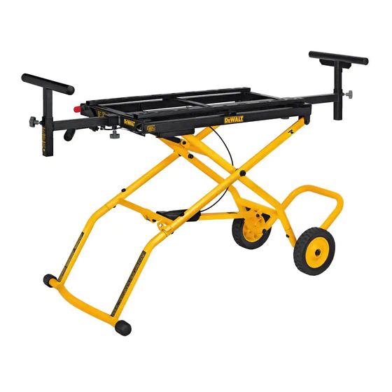
- Page 2 DWX726 Universal Miter Saw/Planer Stand Components List FIG. 1 A. Mounting rails B. Work support arm C. Storage foot D. Wheels E. Leg extension F. Vertical locking knob G. Horizontal locking knob H. Extension arm I. Handle...
-
Page 3: Safety Rules
WARNING: To reduce the risk of injury, keep both hands on Defi nitions: Safety Guidelines handle when raising and lowering the stand. The stand has The definitions below describe the level of severity gas assist lifting and may raise unexpectedly when lever is for each signal word. -
Page 4: Unpacking And Cleaning
Carton Contents using a soft cloth moistened with mineral spirits, paint thinner or denatured alcohol. 1 Rolling miter saw/planer stand NOTICE: Do not use highly volatile solvents such as gasoline, 1 Leg extension naphtha, acetone or lacquer thinner for cleaning your stand. 1 Storage foot Components (Fig. - Page 5 1. With stand upside down, insert the leg extension (E) in the FIG 4 stand (K). 2. Align the holes and install two M8 x 15 mm buttonhead screws (L) with curved washers (M). 3. Tighten securely with the supplied hex wrench. L, M FIG.
- Page 6 4. Attach the other wheel in the same manner. ATTACHING THE STORAGE FOOT (FIG. 7) FIG. 5 IMPORTANT: Turn the stand right side up so the wheels and leg extension sit level on the floor but the stand is not in a raised position. 1.
- Page 7 4. Insert the assembled extension work support arm (B) with the FIG. 8 small black cap (inset, Fig. 10) into the hole (W) of the stand closest to the red activating lever. Push the arm in to lock in place. 5.
- Page 8 2. Using a crescent wrench or 1/2 inch open end wrench, tighten the FIG. 13 screw securely. 3. Repeat for the other cord wrap. FIG. 11 FIG. 12 2. Slide the mounting rails (A) to fit the width of the tool. Ensure the ATTACHING THE TOOL (FIG.
- Page 9 NOTICE: To prevent binding and/or inaccuracy, ensure the plywood WARNING: STABILITY HAZARD. If the tool’s mounting holes do is not warped or uneven. If binding and/or inaccuracy occurs, replace not line up with the slots in the mounting rails, mount the miter saw the plywood with a non-warped, even piece of plywood.
- Page 10 WARNING: Planers MUST be mounted in the orientation shown WARNING: The cuttinghead MUST be raised on all miter in Figure 16. saws, compound miter saws and sliding compound miter saws. All sliding compound miter saws MUST be locked in the rear position.
-
Page 11: Operation
OPERATION TO ADJUST EXTENSION WORK SUPPORT HEIGHT 1. Turn the vertical lock knob (F). WARNING: To reduce the risk of injury, keep both hands on 2. Adjust the extension work support to the desired height. handle and the right foot on the extension leg when raising and 3. - Page 12 For further detail of warranty coverage and warranty repair information, visit www.dewalt.com or call 1-800-4-D WALT (1-800-433-9258). This warranty does not apply to accessories or damage caused where repairs have been made or attempted by others.
- Page 13 FREE WARNING LABEL REPLACEMENT: If your warning labels become illegible or are missing, call 1-800-4-D WALT (1-800-433-9258) for a free replacement.
- Page 14 Plate-forme mobile pour scie à onglet/raboteuse DWX726 Description de l’établi FIG. 1 A. Rails de fixation B. Bras de support d’ouvrage C. Pied de rangement D. Roues E. Rallonge de pied F. Bouton de verrouillage vertical G. Bouton de verrouillage horizontal H.
-
Page 15: Règles De Sécurité
RÈGLES DE SÉCURITÉ Défi nitions : lignes directrices en AVERTISSEMENT : pour votre sécurité, lire le manuel de matière de sécurité l’utilisateur respectif à l’outil avant l’utilisation de tout Les définitions ci-dessous décrivent le niveau de danger pour accessoire. Tout manquement à ces avertissements augmente chaque mot-indicateur employé. -
Page 16: Montage
1 Vis à tête ronde M6 x 10 mm • Ne pas modifier la plateforme ou l’utiliser à des fins pour lesquelles elle n’a pas été conçue. 1 Rondelle de blocage M6 • Porter SYSTÉMATIQUEMENT une protection oculaire. Tout 1 Clé hexagonale utilisateur ou individu présent doit porter une protection oculaire Outils nécessaires homologuée ANSI Z87.1. - Page 17 INSTALLATION DE LA RALLONGE DE PIED (FIG. 2, 3) INSTALLATION DU RACCORD DE ROUE/PIED DE RANGEMENT (FIG. 4) IMPORTANT : Disposer la plateforme à l’envers sur le sol ou sur une table plane et stable, comme illustré en figure 2. 1. Avec la plateforme toujours à l’envers, insérez le raccord de roue/ pied de rangement (N) dans la plateforme (K) avec la rallonge de FIG.
- Page 18 2. Installez l’une des roues (D) sur l’essieu avec la partie la plus FIG. 6 FIG. 7 longue du moyeu orientée vers l’intérieur. 3. Placez la rondelle (Q) sur l’essieu et rattachez un écrou (R). Resserrez l’écrou. REMARQUE : attention à ne pas trop serrer. Trop serrer pourrait compromettre la rotation de la roue.
- Page 19 POUR LEVER ET ABAISSER LA PLATEFORME (FIG. 8) INSTALLATION DES SUPPORTS TÉLESCOPIQUES (FIG. 9, 10) 1. Placez votre pied droit sur le pied de la rallonge de pied (E). IMPORTANT : S’assurer que le côté le plus long du « T » sur le bras de support (B) est orienté...
- Page 20 INSTALLATION DES CROCHETS POUR ENROULER LE AVERTISSEMENT : pour réduire tout risque de dommages CORDON ÉLECTRIQUE (FIG. 11, 12) corporels, arrêter et débrancher la scie à onglet ou la raboteuse REMARQUE : installer les crochets (X) à l’opposé l’un de l’autre pour du secteur avant de les assembler à...
- Page 21 4. Assurez-vous que les trous de montage (CC) sur les pieds de AVERTISSEMENT : RISQUES D’INSTABILITÉ. Si les trous l’outil s’alignent bien avec les orifices du rail (DD) et les écrous de montage de l’outil ne s’alignent pas sur les orifices des rails de captifs (EE) logés dans les rails de fixation.
- Page 22 TEST DE STABILITÉ (FIG. 16–17) AVERTISSEMENT : RISQUES D’INSTABILITÉ. Toute quincaillerie utilisée doit être d’un grade 2 minimum. Elle doit dépasser d’au moins La plateforme mobile pour scie à onglet/raboteuse a été conçue pour 31,8 mm (1-1/4 po) la base de la scie installée. être utilisée avec une grande variété...
- Page 23 Se reporter à la section Pour lever et abaisser la plateforme sous 1. Assurez-vous que l’outil FIG 17 le paragraphe Assemblage pour ajuster la plateforme à la hauteur est solidement arrimé à désirée. la plateforme, et est arrêté et déconnecté EXTENSION DES SUPPORTS TÉLESCOPIQUES (FIG.
-
Page 24: Stockage Et Transport
à une usure normale ou à une mauvaise utilisation de l’outil. Pour plus de détails relatifs à la couverture de la garantie et aux réparations sous garantie, visiter le site Web www.dewalt.com ou composer le 1-800-4-D WALT (1-800-433-9258). Cette garantie ne s’applique pas aux accessoires ni aux dommages causés par des réparations... - Page 25 En plus de la garantie, les outils D WALT sont couverts par notre : SERVICE D’ENTRETIEN GRATUIT DE 1 AN WALT entretiendra l’outil et remplacera les pièces usées par une utilisation normale et ce, gratuitement, à tout instant pendant la première année à compter de la date d’achat. GARANTIE DE REMBOURSEMENT DE 90 JOURS Si vous n’êtes pas entièrement satisfait des performances de votre outil électrique, laser ou de votre marteau-cloueur...
- Page 26 DWX726 Base de soporte rodante para sierra para corte de ingletes/cepiladora Lista de piezas FIG. 1 A. Rieles de montaje B. Brazo de apoyo de la pieza de trabajo C. Pie para almacenamiento D. Ruedas E. Extensión de la pata F.
-
Page 27: Reglas De Seguridad
producirse lesiones corporales y graves daños a la herramienta Defi niciones: Normas de y al accesorio. Cuando realice el mantenimiento de esta seguridad herramienta, utilice únicamente repuestos originales. Las siguientes definiciones describen el nivel de gravedad ADVERTENCIA: El incumplimiento con estas reglas puede de cada palabra de señal. -
Page 28: Desembalaje Y Limpieza
• SIEMPRE use protección ocular. Todos los usuarios y las personas 1 Tornillo de cabeza abombada M6 de 10 mm circunstantes deben llevar protección ocular en conformidad con 1 Arandela de fijación M6 ANSI Z87.1. 1 Llave hexagonal • Use SIEMPRE gafas de seguridad. Los anteojos de diario NO Herramientas requeridas SON gafas de seguridad. - Page 29 INSTALACIÓN DE LA PATA DE EXTENSIÓN (FIG. 2, 3) INSTALACIÓN DEL CONECTOR DE LA RUEDA Y PIE PARA ALMACENAMIENTO (FIG. 4) IMPORTANTE: Coloque el soporte boca abajo sobre el piso o sobre una mesa nivelada y estable como lo muestra la Figura 2. 1.
- Page 30 2. Coloque una de las ruedas (D) en el eje con la parte más larga del FIG. 6 FIG. 7 cubo de la rueda mirando hacia adentro. 3. Coloque la arandela (Q) en el eje e instale la tuerca (R). Ajuste la tuerca.
- Page 31 PARA SUBIR O BAJAR EL SOPORTE (FIG. 8) INSTALACIÓN DE LA EXTENSIÓN DEL SOPORTE PARA TAREAS (FIG. 9, 10) 1. Coloque su pie derecho en la parte de abajo de la pata de extensión (E). IMPORTANTE: Asegúrese de que el extremo más largo de la “T” en el brazo de soporte para tareas (B) esté...
- Page 32 5. Repita para el otro brazo de soporte para tareas en el extremo manual como las del manual del fabricante de su herramienta antes de opuesto. Empuje hacia abajo el brazo para fijarlo en su lugar. operarla. El no respetar estas advertencias puede resultar en lesiones corporales graves y daños serios a la herramienta.
- Page 33 3. Coloque la sierra ingleteadora o máquina cepilladora en los rieles ADVERTENCIA: PELIGRO DE INESTABILIDAD. Si los orificios de montaje (A). Centre la herramienta en el soporte, tanto por de montaje de la herramienta no quedan alineados con las ranuras delante y por detrás como de lado a lado.
- Page 34 PRUEBA DE ESTABILIDAD DEL PRODUCTO (FIG. 16–17) ADVERTENCIA: PELIGRO DE INESTABILIDAD. Todos los accesorios de montaje que utilice deberán ser como mínimo grado 2. La base de soporte rodante para sierra para corte de ingletes/ Los accesorios de montaje deberán tener 31,8 mm (1-1/4 pulg.) cepilladora está...
-
Page 35: Operación
PARA EXTENDER LAS EXTENSIONES DE SOPORTE PARA FIG 17 1. Verifique TAREAS (FIG. 18) herramienta quede bien montada en el soporte 1. Gire la perilla de fijación horizontal (G) en dirección contraria a las y que esté apagada y manillas del reloj. desenchufada. -
Page 36: Almacenamiento Y Transporte
Industrial Tool Co., 701 East Joppa Road, Baltimore, MD 21286, FIG 19 llame al 1-800-4-D WALT (1-800-433-9258) o visite nuestro sitio Web www.dewalt.com. Reparaciones Para garantizar la SEGURIDAD y la CONFIABILIDAD, deberán hacerse reparaciones, mantenimiento y ajustes de esta herramienta... - Page 37 Nombre y domicilio del distribuidor donde se adquirió el producto: inadecuada. Para obtener información detallada sobre la cobertura de la garantía y sobre reparaciones, visite nuestra página Web www. ___________________________________________________________ dewalt.com o llame al 1-800-4-D WALT (1-800-433-9258). Esta...
- Page 38 garantía no se extiende a los accesorios o a los daños causados por terceros al intentar realizar reparaciones. Esta garantía le concede derechos legales específicos; usted goza también de otros derechos que varían según el estado o provincia. Además de la garantía, las herramientas D WALT están cubiertas por nuestro: SERVICIO GRATUITO DE 1 AÑO...
- Page 40 WALT Industrial Tool Co., 701 East Joppa Road, Baltimore, MD 21286 (JUN11) Part No. N116787 DWX726 Copyright © 2011 D WALT The following are trademarks for one or more D WALT power tools: the yellow and black color scheme; the “D” shaped air intake grill; the array...