Table of Contents
Advertisement
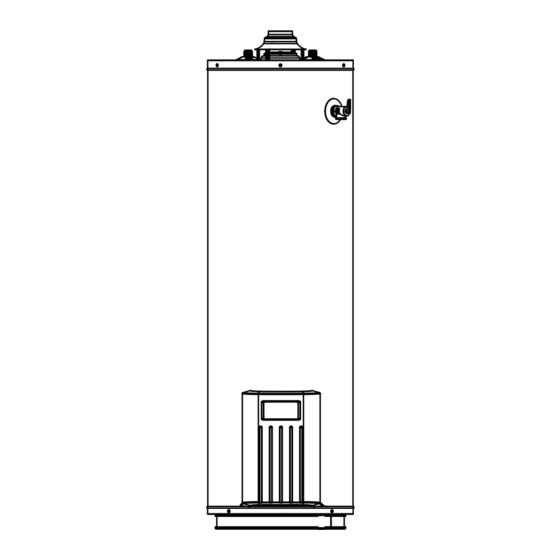
Owner's Manual
POWER MISER™ 12
GAS WATER HEATER
FOR POTABLE WATER HEATING ONLY.
NOT SUITABLE FOR SPACE HEATING.
NOT FOR USE IN MOBILE HOMES.
MODEL NO.
153.331472
40 Gallon
153.331572
50 Gallon
This water heater complies with ANSI Z21.10.1-
current edition regarding the accidental or
unintended ignition of fl ammable vapors, such
as those emitted by gasoline.
ADVERTENCIA
Si no puede leer o entender el inglés y necesita el manual de
instrucciones en español, puede solicitarlo al 1-800-821-2017. NO
TRATE DE INSTALAR U OPERAR ESTE CALENTADOR DE AGUA
SI NO ENTIENDE LAS INSTRUCCIONES. No hacer caso de esta
advertencia podría originar lesiones graves o mortales.
Sears, Roebuck and Co., Hoffman Estates, IL 60179 U.S.A
PRINTED IN THE U.S.A 0608
• Safety Instructions
• Installation
• Operation
• Care and Maintenance
• Troubleshooting
• Parts List
AN ODORANT IS ADDED TO THE GAS USED BY THIS WATER HEATER.
www.sears.com
1
For Your Safety
PART NO. 186498-000
Advertisement
Table of Contents
Troubleshooting

Related Manuals for Kenmore 153.331572


Summary of Contents for Kenmore 153.331572
-
Page 1: For Your Safety
PRINTED IN THE U.S.A 0608 • Safety Instructions • Installation • Operation • Care and Maintenance • Troubleshooting • Parts List For Your Safety AN ODORANT IS ADDED TO THE GAS USED BY THIS WATER HEATER. www.sears.com PART NO. 186498-000... -
Page 2: Safe Installation, Use And Service
Your safety and the safety of others is extremely important in the installation, use and servicing of this water heater. Many safety-related messages and instructions have been provided in this manual and on your own water heater to warn you and others of a potential injury hazard. - Page 3 Do not store or use gasoline or other flammable vapors and liquids in the vicinity of this or any other appliance. Avoid all ignition sources if you smell Natural or LP gas. Do not expose water heater control to excessive gas pressure. Use only gas shown on rating plate.
-
Page 4: Table Of Contents
CUSTOMER RESPONSIBILITIES ... 7 PRODUCT SPECIFICATIONS ... 7 MATERIALS AND BASIC TOOLS NEEDED ... 8 TYPICAL INSTALLATION ... 9 IMPORTANT INFORMATION ABOUT THIS WATER HEATER ... 10 Installation Checklist ... 10 INSTALLATION INSTRUCTIONS ... 11-14 Removing the Old Water Heater ...11 Location Requirements ... - Page 5 Temperature-Pressure Relief Valve Operation ... 26 Draining and Flushing ... 26-27 Service ... 27 MAINTENANCE OF YOUR WATER HEATER ... 28-31 Replacement Parts ... 28 External Inspection & Cleaning of the Base-Ring Filter ... 28 Removing the Manifold/Burner Assembly ... 28 Removing the Burner from the Manifold/Burner Assembly ...
-
Page 6: Product Warranty
Supply a free water heater for one that develops a leak. For the second through the twelfth year from the purchase date, you must pay the labor cost for installation of parts or water heater. For commercial, institutional, industrial or residential use by two or more families, the above limited warranty is only for two years. -
Page 7: Customer Responsibilities
Thank You for purchasing a Kenmore water heater. Properly installed and maintained, it should give you years of trouble free service. If you should decide that you want the new water heater professionally installed by Sears call 1-800-4-MY-HOME prompt, quality installation by Sears authorized contractors. -
Page 8: Materials And Basic Tools Needed
USE FOR WATER AND GAS TAPE (USE ONLY ON WATER CONNECTIONS) 6 FOOT TAPE GARDEN HOSE WATER HEATER INSTALLATION KIT WITH FLEXIBLE CONNECTORS FOR 3/4” (19.05 mm) OR 1/2” (12.7 mm) THREADED OR COPPER PLUMBING AND FLEXIBLE WATER HEATER GAS CONNECTOR WITH FITTINGS. -
Page 9: Typical Installation
GET TO KNOW YOUR WATER HEATER - GAS MODELS A Vent Pipe B Draft Hood C Anode (Not Shown) D Hot Water Outlet E Insulation F Gas Supply Piping G Manual Gas Shut-off Valve H Ground Joint Union I Drip Leg (Sediment Trap) * INSTALL IN ACCORDANCE WITH LOCAL CODES. -
Page 10: Important Information About This Water Heater
IMPORTANT INFORMATION ABOUT THIS WATER HEATER This gas water heater was manufactured to voluntary safety standards to reduce the likelihood of a flammable vapor ignition incident. The new technology used in meeting these standards makes this product more sensitive to installation errors. Please review the following checklist and make any required installation upgrades or changes. -
Page 11: Installation Instructions
OUTER DOOR 6” MAXIMUM AIR GAP If you have copper piping to the water heater, the two copper water pipes can be cut with a hacksaw approximately four inches away from where they connect to the water heater. See Figure 6. This will avoid cutting off pipes too short. -
Page 12: Location Requirements
(Figure 8). • If the water heater is located in an area that is subjected to lint and dirt, it may be necessary to periodically clean the base-ring filter and flame-arrestor (see External Inspection &... -
Page 13: Insulation Blankets
Insulation Blankets Insulation blankets available to the general public for external use on gas water heaters are not necessary with Kenmore products. The purpose of an insulation blanket is to reduce the standby heat loss encountered with storage tank heaters. Your... -
Page 14: Filling The Water Heater
FIGURE 10. Filling the Water Heater Never use this water heater unless it is completely full of water. To prevent damage to the tank, the tank must be fi lled with water. Water must fl ow from the hot water faucet before turning “ON” gas to the water heater. -
Page 15: Gas Supply
While purging the gas piping system of air, ensure that the fuel is not spilled in the area of the water heater installation, or any source of ignition. If the fuel is spilled while purging the piping system of air follow the “WHAT TO DO IF YOU SMELL... -
Page 16: Combustion Air Supply & Ventilation
Combustion and ventilation air requirements are determined by the location of the water heater. The water heater may be located in either an open (unconfined) area or in a confined area or small enclosure such as a closet or small room. -
Page 17: All Air From Outdoors
Vertical Ducts Horizontal Ducts Single Opening Example: A water heater with an input rating of 50,000 BTUH using horizontal ducts would require each opening to have a minimum free area of 25 square inches. Minimum free area = 50,000 BTUH x 1 sq. in. / 2000 BTUH = 25 sq. -
Page 18: Vent Pipe System
Correct installation of the vent pipe system is mandatory for the proper and efficient operation of this water heater and is an important factor in the life of the unit. The vent pipe must be installed according to all local and state codes or, in the absence of local and state codes, the “National... -
Page 19: Vent Connectors
Vertical exhaust gas vents must be installed with U.L. listed type B vent pipe according to the vent manufacturer’s instructions and the terms of its listing. It must be connected to the water heater’s draft hood by a listed vent connector or by directly originating at the draft hood opening. -
Page 20: Water System Piping
A temperature and pressure relief valve must be installed in the opening marked “Temperature and (T & P) Relief Valve” on the water heater. A discharge line must be added to the opening of the T&P Relief Valve. Follow the instructions under “Temperature and Pressure Relief Valve.”... -
Page 21: Closed System/Thermal Expansion
IMPORTANT: Only a new temperature and pressure relief valve should be used with your water heater. Do not use an old or existing valve as it may be damaged or not adequate for the working pressure of the new water heater. -
Page 22: To Turn Off Gas To Appliance
Check the rating plate near the gas control valve/thermostat for the correct gas. Do not use this water heater with any gas other than the one listed on the rating plate. If you have any questions or doubts, consult your gas supplier or gas utility company. -
Page 23: Checking The Draft
FIGURE 27. Emergency Shut Down IMPORTANT: Should overheating occur or the gas supply fails to shut off, turn off the water heater’s manual gas control valve and call a qualified technician. Water Temperature Regulation Due to the nature of the typical gas water heater, the water temperature in certain situations may vary up to 30°F (16.7 °C) - Page 24 WHITE RODGERS GAS VALVE GAS CONTROL KNOB (OFF-PILOT-ON) 160°F 150°F INDEX BAR 140°F TEMPERATURE DIAL NOTE: During low demand periods when hot water is not being used, a lower thermostat setting will reduce energy losses and may satisfy your normal hot water needs. If hot water use is expected to be more than normal, a higher thermostat setting may be required to meet the increased Temperature...
-
Page 25: Service And Adjustment
Soot build-up indicates a problem that requires correction before further use. Turn “OFF” gas to water heater and leave off until repairs are made, because failure to correct the cause of the sooting can result in a fi re causing death, serious injury, or property damage. -
Page 26: Housekeeping
Housekeeping Vacuum around base of water heater for dust, dirt, and lint on a regular basis. Fire and Explosion Harzard Do not obstruct combustion air openings at the bottom of the water heater. Do not use or store flammable vapor products such as gasoline,... -
Page 27: Service
To drain the tank, perform the following steps: Turn off the gas to the water heater at the manual gas shut- off valve. Close the cold water inlet valve. Open a nearby hot water faucet. Connect a hose to the drain valve and terminate it to an adequate drain. -
Page 28: Maintenance Of Your Water Heater
At least annually, check the base-ring filter (Figure 38) for any dust or debris that may have accumulated on the filter screen. NOTE: If the water heater is located in an area that is subjected to lint and dirt, it may be necessary to check the base-ring filter more frequently. -
Page 29: Replacing The Pilot/ Pilot Tube Assembly
Position the new thermocouple through the bottom opening of the two piece wire connector (Figure 34). Be sure igniter wire is positioned through the small opening of the two piece wire connector. Re-attach the burner. Note the orientation of the burner (Figure 33.) See “Replacing the Manifold/Burner Assembly.”... -
Page 30: Replacing The Manifold/Burner Assembly
IMPORTANT: Do not operate the water heater if the door gasket does not create a seal between the manifold door and the combustion chamber. -
Page 31: Testing The Igniter System
Testing the Igniter System Turn off the gas to the water heater at the manual gas shut-off valve. Watch the electrode tip while activating the igniter. A visible spark should jump from the electrode. To avoid shock, do not touch the burner or any metal part on the pilot or pilot assembly. -
Page 32: Troubleshooting Guide
If the flame is not FIGURE 42. -
Page 33: Operational Conditions
Condensation Whenever the water heater is filled with cold water, some condensate will form while the burner is on. A water heater may appear to be leaking when in fact the water is condensation. This usually happens when: •... -
Page 34: Leakage Checkpoints
Water in the water heater bottom or on the floor may be from condensation, loose connections, or the relief valve. DO NOT replace the water heater until a full inspection of all possible water sources is made and necessary corrective steps taken. -
Page 35: Troubleshooting Chart
Repair faucets Advise customer Insulate piping Insulate piping Check with gas utility company Provide ventilation to water heater. Check flue way, flue baffle, and burner Clean flue, locate source and correct Check with gas utility company Replace thermostat Turn temperature dial to desired setting... - Page 36 Low gas pressure POSSIBLE CAUSE(S) CORRECTIVE ACTION Replace thermostat Replace thermostat Provide ventilation to water heater. Check flue way, flue baffle, and burner Clean, locate source and correct Provide fresh air ventilation Provide ventilation to water heater. Check flue way, flue baffle, burner...
-
Page 37: Pilot Light Troubleshooting Flowchart
Check the water heater for a Flammable Vapor (FV) event. Note: it may be necessary to remove the manifold door assembly to visually inspect the water heater. Reference the “Maintenance of your Water Heater” section of this manual for removal instructions. -
Page 38: Parts Order List
Thermocouple Two-Piece Wire Connector w/ Clip * Not Shown. Now that you have purchased your gas water heater, should a need ever exist for repair parts or service, simply contact any Sears Service Center or call 1-800-4-MY-HOME (1-800-469-4663). Be sure to provide all pertinent facts when you call or visit. - Page 39 NOTES...
- Page 40 Get it fixed, at your home or ours! For expert troubleshooting and home solutions advice: For repair – in your home – of all major brand appliances, lawn and garden equipment, or heating and cooling systems, no matter who made it, no matter who sold it! For the replacement parts, accessories and owner’s manuals that you need to do-it-yourself.
Need help?
Do you have a question about the 153.331572 and is the answer not in the manual?
Questions and answers