Table of Contents
Advertisement
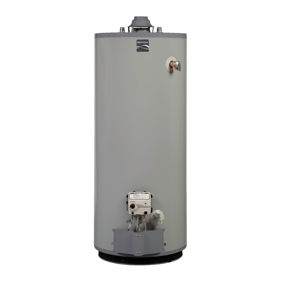
Use & Care Guide
Model No.
153.331140
40 Gallon
153.331150
50 Gallon
Kenmore
Gas Water Heater
For potable water heating only.
Not suitable for space heating.
Not for use in mobile homes.
INSTALLER: Affix these instructions to or near
the water heater.
OWNER: Retain these instructions for future
reference.
FOR YOUR SAFETY: An odorant is added to
the gas used by this water heater.
ADVERTENCIA
Si no puede leer o entender el inglés y necesita el manual de
instrucciones en español, puede solicitarlo al 1-800-821-2017. NO
TRATE DE INSTALAR U OPERAR ESTE CALENTADOR DE AGUA
SI NO ENTIENDE LAS INSTRUCCIONES. No hacer caso de esta
advertencia podría originar lesiones graves o mortales.
P/N 320391-000 (1110)
Sears Brands Management Corporation,
Hoffman Estates, IL 60179 U.S.A.
www. kenmore.com
www.sears.com
®
1
LOW LEAD
COMPLIANT
Advertisement
Table of Contents
Troubleshooting

Related Manuals for Kenmore 153.331140


Summary of Contents for Kenmore 153.331140
- Page 1 Use & Care Guide Model No. 153.331140 40 Gallon 153.331150 50 Gallon LOW LEAD COMPLIANT Kenmore ® Gas Water Heater For potable water heating only. Not suitable for space heating. Not for use in mobile homes. INSTALLER: Affix these instructions to or near the water heater.
-
Page 2: Safe Installation, Use And Service
SAFE INSTALLATION, USE AND SERVICE Your safety and the safety of others is extremely important in the installation, use and servicing of this water heater. Many safety-related messages and instructions have been provided in this manual and on your own water heater to warn you and others of a potential injury hazard. - Page 3 Fire or Explosion Hazard Do not store or use gasoline or other flammable vapors and liquids in the vicinity of this or any other appliance. Avoid all ignition sources if you smell Natural or LP gas. Do not expose water heater control to excessive gas pressure.
-
Page 4: Table Of Contents
TABLE OF CONTENTS SAFE INSTALLATION, USE AND SERVICE ....................2 SAFETY PRECAUTIONS ........................... 2-3 PRODUCT WARRANTY ..........................6 CUSTOMER RESPONSIBILITIES ......................... 7 PRODUCT SPECIFICATIONS ........................8 MATERIALS AND BASIC TOOLS NEEDED ....................9 TYPICAL INSTALLATION ..........................10 IMPORTANT INFORMATION ABOUT THIS WATER HEATER ..............11 Installation Checklist ..............................11 INSTALLATION INSTRUCTIONS ...................... - Page 5 OPERATING YOUR WATER HEATER ....................23-26 Lighting Instructions ............................23-24 Checking the Draft ..............................25 Burner Flames ................................ 25 Emergency Shut Down ............................25 Water Temperature Regulation .......................... 25-26 Operating the Temperature Control System ......................26 SERVICE AND ADJUSTMENT ....................... 27-29 Vent System Inspection ............................
-
Page 6: Product Warranty
Leaks in pipes or fi ttings Master Protection Agreements • $250 Food Loss Protection annually for any food spoilage Congratulations on making a smart purchase. Your new Kenmore ® that is the result of mechanical failure of any covered product is designed and manufactured for years of dependable refrigerator or freezer. -
Page 7: Customer Responsibilities
CUSTOMER RESPONSIBILITIES • Thank You for purchasing a Kenmore water heater. Properly installed Massachusetts Code requires this water heater to be installed in and maintained, it should give you years of trouble free service. If accordance with Massachusetts 248-CMR 2.00: State Plumbing you should decide that you want the new water heater professionally Code and 248-CMR 5.00. -
Page 8: Product Specifications
RATE GALS. VENT PIPE INCHES INCHES (mm) (Btu/hr) PER HOUR DIA. INCHES (mm) HEIGHT TO @ 90°F RISE (mm) JACKET TOP 153.331140 40 (151) Natural 40,000 40.9 3 (76) or 4 (102) 20 (508) 58.14 (1477) 153.331150 50 (189) Natural 40,000 40.9... -
Page 9: Materials And Basic Tools Needed
MATERIALS AND BASIC TOOLS NEEDED MATERIALS NEEDED To simplify the installation Sears has available the installation parts shown below. You may or may not need all of these materials, depending on your type of installation. M E TA L D R A I N PA N S EXPANSION TANKS FOR A V A I L A B L E 2 0 ”... -
Page 10: Typical Installation
TYPICAL INSTALLATION GET TO KNOW YOUR WATER HEATER - GAS MODELS A Vent Pipe J Inner Door S Gas Control Valve/Thermostat B Draft Hood K Outer Door T Drain Valve C Anode (Not Shown) L Union U Manifold/Burner Assembly D Hot Water Outlet M Inlet Water Shut-off Valve V Flue E Insulation... -
Page 11: Important Information About This Water Heater
IMPORTANT INFORMATION ABOUT THIS WATER HEATER This gas water heater was manufactured to voluntary safety standards to reduce the likelihood of a flammable vapor ignition incident. The new technology used in meeting these standards makes this product more sensitive to installation errors. Please review the following checklist and make any required installation upgrades or changes. -
Page 12: Installation Instructions
INSTALLATION INSTRUCTIONS Removing the Old Water Heater Attach a hose to the water heater drain valve and put the other end in a fl oor drain or outdoors. (See Figures 2 and 5.) Open the water heater drain valve. The water passing out of the drain valve may be extremely hot. -
Page 13: Location Requirements
Location Requirements area of the water heater, leave the area immediately and call the fire department from a neighbor’s home. Do not attempt to clean the spill until all ignition sources have been extinguished. WARNING WARNING Carbon Monoxide Poisoning Hazard Fire or Explosion Hazard Do not install in a mobile home. -
Page 14: Insulation Blankets
Insulation Blankets Insulation blankets available to the general public for external use on gas water heaters are not necessary with Kenmore products. The purpose of an insulation blanket is to reduce the standby heat loss encountered with storage tank heaters. Your... -
Page 15: Filling The Water Heater
• Open the cold water supply valve to the water heater. VENT NOTE: The cold water supply valve must be left open BACK when the water heater is in use. SIDES CEILING • To ensure complete fi lling of the tank, allow air to exit by opening the nearest hot water faucet. -
Page 16: Gas Supply
Gas Pressure the fuel is not spilled in the area of the water heater installation, or any source of ignition. If the fuel is spilled while purging the piping system of air follow the “WHAT TO DO IF YOU SMELL GAS”... -
Page 17: Combustion Air Supply & Ventilation
COMBUSTION AIR SUPPLY & VENTILATION WARNING TABLE 3 120,000 25 x 30 Carbon Monoxide Warning 135,000 28 x 30 Follow all the local and state codes or, in the absence of IMPORTANT: local and state codes, the “National Fuel Gas Code”, •... -
Page 18: All Air From Outdoors
gas utilization equipment in the area. If you are unsure that the TABLE 4 structure meets this requirement, contact your local gas utility Minimum Free Area of Permanent Openings for Ventilation company or other qualified agency for a safety inspection. and Combustion Air Supply - All Air from Outdoors Only. -
Page 19: Vent Pipe System
using the manufacturer’s instructions and local codes, rules, or regulations. 1 SQ. INCH PER 2000 BTUH IMPORTANT: If you lack the necessary skills required to properly install this venting system, you should not proceed, but get help from a qualified technician. OUTLET CONFINED Draft Hood Installation... -
Page 20: Vent Connectors
inspection, and replacement. (Figures 20 and 21). • Vent connectors cannot pass through any ceiling, floor, IMPORTANT: This gas vent must be terminated in a vertical firewall, or fire partition. position to facilitate the removal of the burnt gases. • It is recommended (but not mandatory) that a minimum 12 An unused chimney flue or masonry enclosure may be used as a inches of vertical vent pipe be installed on the draft hood... -
Page 21: Water System Piping
WATER SYSTEM PIPING Piping Installation In a closed system use a thermal expansion tank Piping, fittings, and valves should be installed according to the Cold Water Supply to Fixtures installation drawing (Figure 22). If the indoor installation area Hot Water Outlet Main water supply is subject to freezing temperatures, the water piping must be... -
Page 22: Closed System/Thermal Expansion
Closed System/Thermal Expansion For protection against excessive pressures and temperatures, a temperature and pressure relief valve must be installed in the opening marked “T & P RELIEF VALVE.” (See Figure 24). This valve must be design certified by a nationally recognized testing laboratory that maintains periodic inspection of the production of listed equipment or materials as meeting the requirements for Relief Valves for Hot Water Supply Systems, ANSI Z21.22. -
Page 23: Operating Your Water Heater
OPERATING YOUR WATER HEATER WARNING Lighting Instructions Explosion Hazard Read and understand these directions thoroughly before attempting to light or re-light the pilot. Make sure the view port Replace view port if glass is missing is not missing or damaged. (See Figure 34.) Make sure the or damaged. -
Page 24: Lighting Instructions
FOR YOUR SAFETY READ BEFORE LIGHTING WARNING: If you do not follow these instructions exactly, a fire or explosion may result causing property damage, personal injury or loss of life. FLAMMABLE BEFORE LIGHTING: ENTIRE SYSTEM MUST BE FILLED WITH WATER AND AIR PURGED FROM ALL LINES This appliance has a pilot which is lit by a piezo- If you cannot reach your gas supplier, call the fire electric spark gas ignition system. -
Page 25: Checking The Draft
Checking the Draft Water Temperature Regulation WARNING Water temperature over 125°F (52°C) can cause servere burns instantly resulting in severe injury or death. Burn Hazard Children, the elderly, and the physically or mentally disabled are at highest risk for scald injury. Do not touch vent. -
Page 26: Operating The Temperature Control System
Water Temperature Adjustment Gas Control/Temperature Knob The water temperature setting can be adjusted from 55°F to 155°F. Turn the Gas Control/Temperature Knob to the desired 120°F Mark setting/temperature. Status Light NOTE : Some models are certified for 180°F outlet temperatures. See the Data Plate on the front of the water heater for the maximum outlet temperature. -
Page 27: Service And Adjustment
SERVICE AND ADJUSTMENT Vent System Inspection At least once a year, a visual inspection should be made of the main burner and pilot burner. See Figure 30. You should check for sooting. Soot is not normal and will impair proper combustion. Soot build-up indicates a problem that requires correction before further use. -
Page 28: Housekeeping
Housekeeping indicates high water conductivity and should be checked and/or replaced more often than an anode rod that appears to be intact. Replacement of a depleted anode rod can extend the life of Vacuum around base of water heater for dust, dirt, and lint on your water heater. -
Page 29: Service
operation. The water heater should be drained if being shut If the water heater is going to be shut down for an extended down during freezing temperatures. To drain the tank, perform period, the drain valve should be left open. the following steps: IMPORTANT: Condensation may occur when refilling the tank and should not be confused with a tank leak. -
Page 30: Maintenance Of Your Water Heater
MAINTENANCE OF YOUR WATER HEATER Replacement Parts GAS CONTROL VALVE/THERMOSTAT THERMOPILE AND SWITCH WIRE GAS CONTROL/ CONNECTIONS IMPORTANT: The following maintenance procedures are for TEMPERATURE KNOB the FVIR System components and should be performed by a PIEZO IGNITER BUTTON qualified technician. PILOT TUBE MANIFOLD TUBE Replacement parts may be ordered from Sears Parts and... -
Page 31: Replacing The Pilot/ Pilot Tube Assembly
as a bending template for the new pilot assembly. Note Using the pilot/thermopile assembly screw removed earlier reattach the new pilot/thermopile assembly. Reattach the the placement/order of the wires in the manifold component burner to the manifold using the screws removed earlier. block. -
Page 32: Replacing The Manifold/Burner Assembly
Replacing the Manifold/Burner Assembly 10. Follow the lighting instructions on the front of the water heater. With the main burner lit, check for leaks at the manifold and pilot connections by brushing on an WARNING approved noncorrosive leak detection solution, or a mixture of hand dish washing soap and water (one part soap to 15 parts water) or childrens soap bubble solution. -
Page 33: Removing And Replacing The Gas Control Valve/Thermostat
Removing and Replacing the Gas Control Valve/Thermostat IMPORTANT: The gas control valve/thermostat is a standard • Be sure to remove the pilot ferrule nut from the new gas valve with wire leads that connect to a thermal switch. control valve/thermostat. Removing the Gas Control Valve/Thermostat: •... -
Page 34: Troubleshooting Guide
TROUBLESHOOTING GUIDE NOTE: Expansion tanks are pre-charged with a 40 psi air Start Up Conditions charge. If the inlet water pressure is higher than 40 psi, the expansion tank’s air pressure must be adjusted to match Thermal Expansion that pressure, but must not be higher than 80 psi. As water is heated, it expands (thermal expansion). -
Page 35: Operational Conditions
Condensation hot water lines. Contact Sears Service for further information concerning this chlorination treatment and an anode replacement Whenever the water heater is filled with cold water, some kit #9001453. (For short heaters, use anode replacement condensate will form while the burner is on. A water heater may kit #9006299.) Anode replacement and chlorination of the tank appear to be leaking when in fact the water is condensation. - Page 36 appliance. Immediately call a qualifi ed technician to inspect Read this manual first. Then, before checking the water heater, the appliance. Water heaters subjected to a fl ammable vapors make sure the gas supply has been turned “OFF”, and never ignition will require replacement of the entire water heater.
-
Page 37: Troubleshooting Chart
TROUBLESHOOTING CHART PROBLEM POSSIBLE CAUSE(S) CORRECTIVE ACTION BURNER WILL NOT IGNITE Pilot not lit Light pilot Thermostat set too low Turn temp. dial to desired temperature Main burner line clogged Clean, locate source and correct Non-functioning thermostat Check status light codes and reference the “Status Light and Diagnostic Code Base-Ring Filter blocked with lint/dust Troubleshooting Chart”... -
Page 38: Troubleshooting Chart
TROUBLESHOOTING CHART (CONTINUED) PROBLEM POSSIBLE CAUSE(S) CORRECTIVE ACTION SLOW HOT WATER Insufficient combustion air Provide ventilation to water heater. Check flue RECOVERY way, flue baffle, and burner Water heater flue or vent system Clean flue, locate source and correct blocked Low gas pressure Check with gas utility company Improper calibration... -
Page 39: Status Light And Diagnostic Troubleshooting Chart
STATUS LIGHT AND DIAGNOSTIC CODE TROUBLESHOOTING CHART LED STATUS PROBLEM CORRECTIVE ACTION 0 FLASHES (LED NOT LIT) Pilot light is not lit or Thermopile Turn Gas Control Valve/Thermostat knob to OFF. has not yet reached normal Wait 10 minutes, then attempt to relight Pilot by operating temperature. - Page 40 STATUS LIGHT AND DIAGNOSTIC CODE TROUBLESHOOTING CHART LED STATUS PROBLEM CORRECTIVE ACTION 4 FLASHES Control Valve’s Relight pliot and verify 4 flashes. If 4 flashes are temperature sensor has detected observed turn Gas Control Valve/Thermostat knob that the water temperature was too to OFF.
-
Page 41: Pilot Light Troubleshooting Flowchart
PILOT LIGHT TROUBLESHOOTING FLOWCHART Section A: Pilot light will not light (new installation). Section C: Pilot light will not remain lit. Complete this section after completing Section B. Is the manual gas shut-off valve, Turn the manual gas shut-off valve to Check for insufficient combustion air. -
Page 42: Parts Order List
PARTS ORDER LIST KENMORE 12 YEAR GAS WATER HEATER MODEL NUMBERS 153.331140 40 Gallon (Natural) 153.331150 50 Gallon (Natural) Model Numbers Key No. Part Description 153.331140 153.331150 Anode Rod 9003721 9001829 Anode Rod (Secondary) 9003934 9003934 Base-Ring Filter 9006616 9006660... -
Page 43: Notes
NOTES... - Page 44 Get it fixed, at your home or ours! Your Home For troubleshooting, product manuals and expert advice: www.managemylife.com For repair – in your home – of all major brand appliances, lawn and garden equipment, or heating and cooling systems, no matter who made it, no matter who sold it! For the replacement parts, accessories and owner’s manuals that you need to do-it-yourself.