Table of Contents
Advertisement
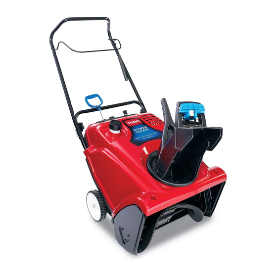
Power Clear 621 ZR/ZE Snowthrower
Model No. 38453—Serial No. 312000001 and Up
Model No. 38454—Serial No. 312000001 and Up
Introduction
This machine is intended to be used by residential
homeowners. It is designed for removing snow from
paved surfaces, such as driveways and sidewalks,
and other surfaces for traffic on residential or
commercial properties. It is not designed for
removing materials other than snow, nor is it
designed for clearing off gravel surfaces.
Read this information carefully to learn how to operate
and maintain your machine properly and to avoid injury
and machine damage. You are responsible for operating
the machine properly and safely.
You may contact Toro directly at www.Toro.com for
machine and accessory information, help finding a
dealer, or to register your machine.
Whenever you need service, genuine Toro parts,
or additional information, contact an Authorized
Service Dealer or Toro Customer Service and have
the model and serial numbers of your machine ready.
Figure 1 identifies the location of the model and serial
numbers on the machine. Write the numbers in the
space provided.
1. Model and serial number location
© 2011—The Toro® Company
8111 Lyndale Avenue South
Bloomington, MN 55420
Figure 1
Register at www.Toro.com.
Model No.
Serial No.
This manual identifies potential hazards and has safety
messages identified by the safety alert symbol (Figure 2),
which signals a hazard that may cause serious injury
or death if you do not follow the recommended
precautions.
Figure 2
1. Safety alert symbol
This manual uses 2 words to highlight information.
Important calls attention to special mechanical
information and Note emphasizes general information
worthy of special attention.
Safety
Read and understand the contents of this manual
before you start the engine.
The safety alert symbol shown in Figure 2 is used to
alert you to potential personal injury hazards. Obey
all safety messages that follow this symbol to avoid
possible injury or death.
Improperly using or maintaining this machine
could result in injury or death. To reduce this
potential, comply with the following safety
instructions.
This machine is capable of amputating hands and
feet and of throwing objects. Failure to observe the
following safety instructions could result in serious
injury.
Training
• Read, understand, and follow all instructions on the
machine and in the manual(s) before operating this
Form No. 3369-495 Rev B
Operator's Manual
Original Instructions (EN)
Printed in the USA
All Rights Reserved
Advertisement
Table of Contents

Related Manuals for Toro Power Clear 621 ZR


Summary of Contents for Toro Power Clear 621 ZR
- Page 1 You are responsible for operating the machine properly and safely. Figure 2 You may contact Toro directly at www.Toro.com for 1. Safety alert symbol machine and accessory information, help finding a dealer, or to register your machine.
- Page 2 machine. Be thoroughly familiar with the controls • Never attempt to make any adjustments while and the proper use of the machine. Know how to the engine is running (except when specifically stop the machine and disengage the controls quickly. recommended by manufacturer).
-
Page 3: Clearing A Clogged Discharge Chute
• Maintain or replace safety and instruction labels, as necessary. • Run the machine a few minutes after throwing snow to prevent freeze-up of the rotor blades. Toro Snowthrower Safety The following list contains safety information specific to Toro products or other safety information that you must know. -
Page 4: Safety And Instructional Decals
Safety and Instructional Decals Important: Safety and instruction decals are located near areas of potential danger. Replace damaged decals. 94-2577 1. To engage the rotor blades, hold the control bar against the handle. 2. To disengage the rotor blades, release the control bar. 117-9102 (Model 38453 only) Order part no. -
Page 5: Setup
Setup Loose Parts Use the chart below to verify that all parts have been shipped. Procedure Description Qty. – No parts required Unfold the handle. Screws Chute assembly Install the discharge chute. Discharge chute handle Unfolding the Handle No Parts Required Procedure Figure 5 1. -
Page 6: Installing The Discharge Chute
Note: The bottle of oil may contain more than is required. Do not overfill or under fill the engine. Max fill: 20 oz. (0.6 l), type: automotive detergent oil with an API service classification of SJ, SL, or higher. Installing the Discharge Chute Use Figure 8 below to select the best oil viscosity for the outdoor temperature range expected: Parts needed for this procedure:... -
Page 7: Adjusting The Control Cable
Operation Note: Determine the left and right sides of the machine from the normal operating position. Adjusting the Control Cable DANGER No Parts Required Gasoline is extremely flammable and explosive. A fire or explosion from gasoline can burn you and others. -
Page 8: Checking The Engine Oil Level
starting, poor engine performance, and may cause internal engine damage. Note: For best results, purchase only the quantity of gasoline that you expect to use in 30 days. Otherwise, you may add fuel stabilizer to newly purchased gasoline to keep it fresh for up to 6 months. Checking the Engine Oil Level Figure 13 Service Interval: Before each use or daily—Check... -
Page 9: Engaging The Rotor Blades
Figure 16 Figure 18 Note: Remove your glove when you push in the primer so that air cannot escape from the primer Important: Run the electric starter no more hole. than 10 times at intervals of 5 seconds on, then Important: Do not use the primer or the choke 5 seconds off. -
Page 10: Disengaging The Rotor Blades
Disengaging the Rotor Blades To disengage the rotor blades, release the control bar (Figure 20). Figure 19 1. Control bar Figure 20 Stopping the Engine To stop the engine, turn the ignition key counterclockwise to the Off position (Figure 21). Figure 21... -
Page 11: Clearing Clogged Discharge Chute
Adjusting the Discharge Chute Preventing Freeze-up after Use and Chute Deflector • Let the engine run for a few minutes to prevent moving parts from freezing. Stop the engine, wait To adjust the discharge chute, move the chute handle for all moving parts to stop, and remove ice and as shown (Figure 22). -
Page 12: Recommended Maintenance Schedule(S)
Maintenance Note: Determine the left and right sides of the machine from the normal operating position. Recommended Maintenance Schedule(s) Maintenance Service Maintenance Procedure Interval • Check the control cable and adjust it if necessary. After the first hour • Check for loose fasteners and tighten them if necessary. •... -
Page 13: Changing The Engine Oil
1/8-inch (2 mm to 3 mm) gap between the control bar and the handle (Figure 24). Note: Moving the Z-fitting higher decreases the gap between the control bar and the handle; moving it lower increases the gap. 3. Hook the spring to the adjuster link and slide the spring cover over the adjuster link. -
Page 14: Servicing The Spark Plug
9. Wait 3 minutes for the oil to settle and add enough to bring it to the point of overflow. 10. Screw the oil fill cap into the oil fill hole, and hand tighten it securely. 11. Wipe up any spilled oil. 12. -
Page 15: Replacing The Drive Belt
12. Install the spark plug and torque it to 20–22 ft-lb (27–30 N-m). 13. Connect the wire to the spark plug. Note: Ensure that the breather tube is routed above the spark plug wire as shown in Figure 35. Figure 35 Figure 33 1. - Page 16 7. Install the curved washer and the rotor pulley bolt and tighten them securely (Figure 36). Note: The concave side of the curved washer goes against the outside of the pulley. 8. Install the brake spring onto the idler arm (Figure 37). 9.
-
Page 17: Storing The Snowthrower
Storage areas before painting, and use a rust preventative to prevent the metal parts from rusting. 15. Tighten any loose fasteners. Repair or replace any Storing the Snowthrower damaged parts. WARNING 16. Cover the machine and store it in a clean, dry place out of the reach of children. - Page 18 Notes:...
- Page 19 Air Induction System Where a warrantable condition exists, The Toro Company and its affiliate, — Air cleaner Toro Warranty Company, promise to repair your engine at no cost to you, including diagnosis, parts, and labor. — Intake manifold — Controlled hot air intake system Manufacturer’s Warranty Coverage...
- Page 20 Countries Other than the United States or Canada Customers who have purchased Toro products exported from the United States or Canada should contact their Toro Distributor (Dealer) to obtain guarantee policies for your country, province, or state. If for any reason you are dissatisfied with your Distributor's service or have difficulty obtaining guarantee information, contact the Toro importer.