Table of Contents
Advertisement
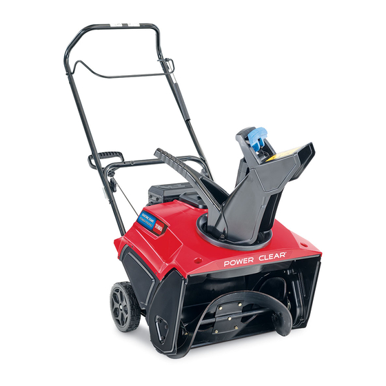
Power Clear
Model No. 38741—Serial No. 404310000 and Up
Model No. 38742—Serial No. 404310000 and Up
Introduction
This machine is intended to be used by residential
homeowners. It is designed primarily for removing
snow from paved surfaces, such as driveways and
sidewalks, and other surfaces for traffic on residential
or commercial properties. It is not designed for
removing materials other than snow, nor is it designed
for clearing gravel surfaces.
Read this information carefully to learn how to operate
and maintain your product properly and to avoid
injury and product damage. You are responsible for
operating the product properly and safely.
You may contact Toro directly at www.Toro.com
for product safety and operation training materials,
accessory information, help finding a dealer, or to
register your product.
Whenever you need service, genuine Toro parts, or
additional information, contact an Authorized Service
Dealer or Toro Customer Service and have the model
and serial numbers of your machine ready.
identifies the location of the model and serial numbers
on the machine. Write the numbers in the space
provided.
Important:
With your mobile device, you can
scan the QR code on the serial number decal (if
equipped) to access warranty, parts, and other
product information.
1. Model and serial number location
© 2019—The Toro® Company
8111 Lyndale Avenue South
Bloomington, MN 55420
®
Figure 1
Figure 1
Register at www.Toro.com.
721 R/E Snowthrower
Model No.
Serial No.
This manual identifies potential hazards and has
safety messages identified by the safety-alert symbol
(Figure
2), which signals a hazard that may cause
serious injury or death if you do not follow the
recommended precautions.
This manual uses 2 words to highlight information.
Important calls attention to special mechanical
information and Note emphasizes general information
worthy of special attention.
Important:
1500 m (5,000 ft) for a continuous period, ensure
that the High Altitude Kit has been installed
so that the engine meets CARB/EPA emission
regulations. The High Altitude Kit increases
engine performance while preventing spark-plug
fouling, hard starting, and increased emissions.
Once you have installed the kit, attach the
high-altitude label next to the serial decal on the
machine. Contact any Authorized Toro Service
Dealer to obtain the proper High Altitude Kit and
high-altitude label for your machine. To locate
a dealer convenient to you, access our website
at www.Toro.com or contact our Toro Customer
Care Department at the number(s) listed in your
Emission Control Warranty Statement. Remove
the kit from the engine and restore the engine to
its original factory configuration when running the
engine under 1500 m (5,000 ft). Do not operate an
engine that has been converted for high-altitude
use at lower altitudes; otherwise, you could
g216757
overheat and damage the engine.
If you are unsure whether or not your machine has
been converted for high-altitude use, look for the
following label
Form No. 3423-722 Rev C
Operator's Manual
Figure 2
Safety-alert symbol
If you are using this machine above
(Figure
3).
Original Instructions (EN)
All Rights Reserved *3423-722* C
Printed in Mexico
g000502
Advertisement
Table of Contents

Related Manuals for Toro Power Clear 721 R


Summary of Contents for Toro Power Clear 721 R
-
Page 1: Introduction
Important calls attention to special mechanical additional information, contact an Authorized Service information and Note emphasizes general information Dealer or Toro Customer Service and have the model worthy of special attention. and serial numbers of your machine ready. Figure 1... -
Page 2: Table Of Contents
Preventing Freeze-up after Use ......11 Maintenance ............12 Recommended Maintenance Schedule(s) ... 12 Maintenance Safety.......... 12 Checking and Adjusting the Control Cable ............12 Inspecting the Rotor Blades......13 decal127-9363 Changing the Engine Oil ........14 Figure 3 Servicing the Spark Plug........15 Replacing the Drive Belt ........ -
Page 3: Figure
Safety and Instructional Decals Safety decals and instructions are easily visible to the operator and are located near any area of potential danger. Replace any decal that is damaged or missing. decal117-9102 117-9102 (Model 38741 only) Order Part No. 117-6036 decal94-2577 1. -
Page 4: Setup
Setup Unfolding the Handle No Parts Required Procedure g263299 Installing the Discharge Chute No Parts Required Procedure g217715... -
Page 5: Filling The Engine With Oil
Filling the Engine with Oil No Parts Required Procedure g253610 Adjusting the Control Cable No Parts Required Procedure Refer to Adjusting the Control Cable (page 13). -
Page 6: Product Overview
Product Overview Inspect the electrical cord before plugging it into a power source. If the cord is damaged, replace it. Unplug the power cord whenever you are not starting the machine. • Wear appropriate clothing, including eye protection; long pants; substantial, slip-resistant footwear;... -
Page 7: Filling The Fuel Tank
Filling the Fuel Tank Do not fill above the bottom of the fuel tank neck (Figure • For best results, use only clean, fresh (less than 30 days old), unleaded gasoline with an octane rating of 87 or higher ((R+M)/2 rating method). •... -
Page 8: Starting The Engine
• causes distractions; otherwise, injury or property After striking a foreign object, shut off the engine, damage may occur. remove the ignition key (electric-start models only), inspect the machine for damage. Repair any • Exercise caution to avoid slipping or falling, damage before starting the machine. -
Page 9: Engaging The Rotor Blades
g258356 Figure 10 Using Recoil Start Note: Remove your glove when you push in the primer so that air cannot escape from the primer hole. Important: Do not use the primer or the choke if the engine has been running and is hot. Excessive priming may flood the engine and prevent it from starting. -
Page 10: Disengaging The Rotor Blades
Disengaging the Rotor Blades To disengage the rotor blades, release the control bar (Figure 13). g001128 Figure 15 1. Chute handle 2. Chute-deflector handle Clearing a Clogged g011230 Discharge Chute Figure 13 To clear the chute: • Shut the engine off! Shutting Off the Engine •... -
Page 11: After Operation
After Operation After Operation Safety General Safety • Never store the machine with fuel in the fuel tank inside a building where ignition sources are present, such as hot water heaters, space heaters, or clothes dryers. Allow the engine to cool before storing the machine in any enclosure. -
Page 12: Maintenance
• Do not change the governor settings on the engine. Figure 16 Purchase only genuine Toro replacement parts 1. Control bar 2. 1/16 inch to 1/8 inch (2 and accessories. mm to 3 mm) gap Checking and Adjusting the... -
Page 13: Inspecting The Rotor Blades
Adjusting the Control Cable Slide up the spring cover and unhook the spring from the adjuster link (Figure 17). g011232 Figure 18 g006402 1. Upper end of spring 3. Pivot point Figure 17 2. Insert the upper end of 4. Remove the upper end of spring into this hole spring from this hole 1. -
Page 14: Changing The Engine Oil
Changing the Engine Oil With the machine in the operating position, carefully pour oil into the oil-fill hole to the point of overflow (Figure 23). Service Interval: After the first 2 hours Yearly Note: You may tip the machine forward (handle up) to make adding oil easier. -
Page 15: Servicing The Spark Plug
Servicing the Spark Plug Service Interval: Yearly—Service the spark plug and replace it if necessary. Use a NGK BPR6ES or Champion RN9YC spark plug or equivalent. Shut off the engine and wait for all moving parts to stop. Rotate the discharge chute so that it faces forward. -
Page 16: Replacing The Drive Belt
Replacing the Drive Belt Install the spark plug and torque it to 20 to 22 ft-lb (27 to 30 N-m). If the drive belt becomes worn, oil-soaked, excessively Connect the wire to the spark plug. cracked, frayed, or otherwise damaged, replace the belt. -
Page 17: Storage
Storage Note: Route the new drive belt first around the engine pulley, then the idler pulley, and finally around the loose rotor pulley positioned just Storing the Machine above the rotor shaft (Figure 28). Install the rotor pulley onto the rotor shaft (Figure 28). - Page 18 With the ignition key in the O position, pull the recoil-start handle slowly to distribute the oil on the inside of the cylinder. Clean the machine. Touch up chipped surfaces with paint available from an Authorized Service Dealer. Sand affected areas before painting, and use a rust preventative to prevent the metal parts from rusting.
- Page 19 While the exposure from Toro products may be negligible or well within the “no significant risk” range, out of an abundance of caution, Toro has elected to provide the Prop 65 warnings. Moreover, if Toro does not provide these warnings, it could be sued by the State of California or by private parties seeking to enforce Prop 65 and subject to substantial penalties.