
Related Manuals for OKIDATA ML590


Summary of Contents for OKIDATA ML590
- Page 1 Thank You for purchasing this Factory Service Manual on EBAY from PCTECHINFO! Click Here for more Factory Service Manuals for other Computer and Printer / Copier Manufacturers from PCTECHINFO!
- Page 2 OKIDATA Service Training Manual. 09/17/97 Note: This Adobe Acrobat version of the Okidata Service Training Manual was built with the pictures rendered at 300 dpi, which is ideal for printing, but does not view on most displays well.
-
Page 3: Table Of Contents
Table of Contents Page Service Guide ML590/ML591 0 About This Manual Front Cover Copyright Part Number & Manual Revision 1 Product Specifications 1.1 General Information 1.2 Physical Specifications 1.3 Power Requirements 1.4 Environmental Conditions 1.5 Agency Approvals 1.6 Operation Spec's - Print Speed and Character Matrix ..1.6.02 Characters Per Line... - Page 4 Table of Contents Page ..1.10.08 OKISmart Typer Utility ..1.10.09 OKISmart Panel Utility 1.11 Reliability 2 Principles of Operation 2.1 Electrical Operation ..2.1.02 Main Control Board ..Block Diagram ..Program ROM ..RAM ..Character Generator ROM (CG ROM) ..Electrically Erasable Programmable ROM (EEPROM) ..LSI ..2.1.03 Initialization ..2.1.04 Parallel Interface Control...
- Page 5 Table of Contents Page ..Continuous Paper Feed (Push/Pull Tractor Mechanism) ..2.2.06 Paper Detection Mechanism ..2.2.07 Support Protector Mechanism ..2.2.08 Automatic Paper Load ..2.2.09 Paper Park 3 Maintenance & Disassembly ..3.1.01 General Information ..3.1.02 Maintenance Tools ..3.1.03 Maintenance Precautions 3.2 Disassembly/Assembly Procedures ..3.2.01 Preliminary Items ..3.2.02 Printhead Assembly ..3.2.03 Ribbon Protector...
- Page 6 Table of Contents Page ..3.3.04 Menu Operation ..Printing the Menu ..Reset Menu to Factory Defaults ..Limited Operation ..Procedure ..Menu Settings ..3.3.05 Top of Form ..3.3.06 Paper Park ..3.3.07 Tear Feature ..3.3.08 Forms Tear Off 3.4 Cleaning ..3.4.02 Cleaning Schedule ..3.4.03 Cleaning Tools ..3.4.04 Areas to be Cleaned 3.5 Lubrication 3.6 Shipping Instructions...
- Page 7 Table of Contents Page ..RAP 11 Serial Interface Problem 4.8 Printer Tests ..4.8.02 Rolling ASCII Test ..4.8.03 Font Test ..4.8.04 Serial Interface Loopback Test ..Serial Cable Information ..Commonly Used Serial Cable Configurations ..4.8.05 Hexadecimal Dump Mode 4.9 Resistance Checks ..4.9.02 Printhead Interconnect Diagram: Control Board to Printhead ..4.9.03 Line Feed Motor Resistance ..4.9.04 Space Motor Resistance...
- Page 8 Proprinter is a registered trademark of International Business Machine Corporation. Windows is a trademark of Microsoft Corporation. Copyright 1997, Okidata, Division of OKI America, Inc. All rights reserved. See the OKIDATA Business Partner Exchange (BPX) for any updates to this material. (http://bpx.okidata.com)
-
Page 9: About This Manual
Second Edition April, 1994 P/N 59256302 Fourth Revision April, 1994 Third Edition November, 1994 P/N 59256303 Copyright 1997, Okidata, Division of OKI America, Inc. All rights reserved. See the OKIDATA Business Partner Exchange (BPX) for any updates to this material. (http://bpx.okidata.com) -
Page 10: Product Specifications
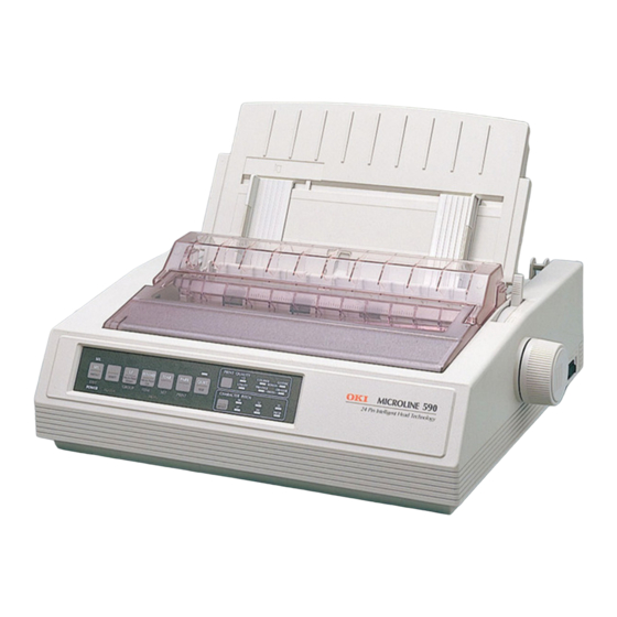
The Microline 590 is an 80 column printer. The Microline 591 is a 132 column printer. Okidata's extended two year limited warranty covers the parts, labor and printhead on both printers. The following items are included with the printer: OKISMART Typer - software which provides the flexibility for the Microline 590/591 to function like a typewriter on checks, labels and envelopes. -
Page 11: Physical Specifications
1.2.02 Printer Weight Microline 590 16.5 pounds (6.5 kilograms) Microline 591 19.8 pounds (8.9 kilograms) Copyright 1997, Okidata, Division of OKI America, Inc. All rights reserved. See the OKIDATA Business Partner Exchange (BPX) for any updates to this material. (http://bpx.okidata.com) -
Page 12: Power Requirements
1.3.03 Power Frequency 120 VAC: 60 Hz +/- 2% 230/240 VAC: 50/60 Hz +/- 2% Copyright 1997, Okidata, Division of OKI America, Inc. All rights reserved. See the OKIDATA Business Partner Exchange (BPX) for any updates to this material. (http://bpx.okidata.com) -
Page 13: Environmental Conditions
While in storage: 14° to 122° F (-10° to 50° C) Storage humidity: 5% to 95% RH Copyright 1997, Okidata, Division of OKI America, Inc. All rights reserved. See the OKIDATA Business Partner Exchange (BPX) for any updates to this material. (http://bpx.okidata.com) -
Page 14: Agency Approvals
FCC Certified per Part 15, Subject J, Class B IEC: IEC 950 VDE: VDE 0805 VDE 0875 Class B BS 7002 Copyright 1997, Okidata, Division of OKI America, Inc. All rights reserved. See the OKIDATA Business Partner Exchange (BPX) for any updates to this material. (http://bpx.okidata.com) - Page 15 Print Speed at Different CPI for the ML 590 Mode Horiz. DPI Vert DPI Utility 17.1 17.1 Copyright 1997, Okidata, Division of OKI America, Inc. All rights reserved. See the OKIDATA Business Partner Exchange (BPX) for any updates to this material. (http://bpx.okidata.com)
-
Page 16: Characters Per Line
Line Inch 17.1 Microline 591 Characters Characters Utility Letter Quality Per Line Per Inch 17.1 Copyright 1997, Okidata, Division of OKI America, Inc. All rights reserved. See the OKIDATA Business Partner Exchange (BPX) for any updates to this material. (http://bpx.okidata.com) -
Page 17: Character Pitches
Chapter 1 Product Specifications 1.6.03 Character Pitches 5, 6, 8.5, 10, 12, 15, 17.1, 20 Copyright 1997, Okidata, Division of OKI America, Inc. All rights reserved. See the OKIDATA Business Partner Exchange (BPX) for any updates to this material. (http://bpx.okidata.com) -
Page 18: Character Sets
UPC A UPC E EAN 8 EAN 13 Interleaved 2 of 5 Code 128 POSTNET Copyright 1997, Okidata, Division of OKI America, Inc. All rights reserved. See the OKIDATA Business Partner Exchange (BPX) for any updates to this material. (http://bpx.okidata.com) -
Page 19: Printer Emulations
1.6.05 Printer Emulations Note: The emulations are co-resident Epson LQ IBM XL 24E (AGM) IBM Proprinter Copyright 1997, Okidata, Division of OKI America, Inc. All rights reserved. See the OKIDATA Business Partner Exchange (BPX) for any updates to this material. (http://bpx.okidata.com) -
Page 20: Fonts
UPC A UPC E EAN 8 EAN 13 Interleaved 2 of 5 Code 128 POSTNET Copyright 1997, Okidata, Division of OKI America, Inc. All rights reserved. See the OKIDATA Business Partner Exchange (BPX) for any updates to this material. (http://bpx.okidata.com) -
Page 21: Front Panel Switches
Paper Park Line Feed Pitch Selection Form Feed Print Quality Selection Top of Form Tear Quiet Copyright 1997, Okidata, Division of OKI America, Inc. All rights reserved. See the OKIDATA Business Partner Exchange (BPX) for any updates to this material. (http://bpx.okidata.com) -
Page 22: Graphics Resolution
Service Guide ML590/ML591 Chapter 1 Product Specifications 1.6.08 Graphics Resolution Graphics Resolution: 360 x 360 DPI maximum Copyright 1997, Okidata, Division of OKI America, Inc. All rights reserved. See the OKIDATA Business Partner Exchange (BPX) for any updates to this material. (http://bpx.okidata.com) -
Page 23: Interface
Page: 17 Service Guide ML590/ML591 Chapter 1 Product Specifications 1.6.09 Interface Standard Parallel Optional RS232C Serial Copyright 1997, Okidata, Division of OKI America, Inc. All rights reserved. See the OKIDATA Business Partner Exchange (BPX) for any updates to this material. (http://bpx.okidata.com) -
Page 24: Line Feed Increments
(8 lines per inch lpi) [0.125 inch (3.175 millimeters)] Variable n/60 inch n/72 inch n/180 inch n/216 inch n/360 inch Copyright 1997, Okidata, Division of OKI America, Inc. All rights reserved. See the OKIDATA Business Partner Exchange (BPX) for any updates to this material. (http://bpx.okidata.com) -
Page 25: Line Feed Time
6 milliseconds 8 lines per inch (lpi) 1 second 5.0 inches (Continuous paper feed rate) Copyright 1997, Okidata, Division of OKI America, Inc. All rights reserved. See the OKIDATA Business Partner Exchange (BPX) for any updates to this material. (http://bpx.okidata.com) -
Page 26: Menu Mode
Group: Selects Group Function Item: Selects Item Set: Selects Item Value Exit: Exits Menu Mode, Enters Select Copyright 1997, Okidata, Division of OKI America, Inc. All rights reserved. See the OKIDATA Business Partner Exchange (BPX) for any updates to this material. (http://bpx.okidata.com) -
Page 27: Paper Feed Methods
Bottom Push Tractor (Bottom) Single-Bin Cut Sheet Feeder (Top) CSF 5000 - Narrow CSF 5001 - Wide Copyright 1997, Okidata, Division of OKI America, Inc. All rights reserved. See the OKIDATA Business Partner Exchange (BPX) for any updates to this material. (http://bpx.okidata.com) -
Page 28: Paper Feed Paths
Bottom Feed (by using an Optional feed mechanism) Special Features Paper Park Automatic Paper Loading Forms Tear Off Copyright 1997, Okidata, Division of OKI America, Inc. All rights reserved. See the OKIDATA Business Partner Exchange (BPX) for any updates to this material. (http://bpx.okidata.com) -
Page 29: Paper Loading
Chapter 1 Product Specifications 1.6.15 Paper Loading Auto Loading (Top Feed) Press LOAD switch for Bottom/Rear Feed Copyright 1997, Okidata, Division of OKI America, Inc. All rights reserved. See the OKIDATA Business Partner Exchange (BPX) for any updates to this material. (http://bpx.okidata.com) -
Page 30: Paper Out Detection
0.5 inches (12.7 mm) Bottom Feed: 0.5 inches (12.7 mm) Top Feed: 0.5 inches (12.7 mm) Copyright 1997, Okidata, Division of OKI America, Inc. All rights reserved. See the OKIDATA Business Partner Exchange (BPX) for any updates to this material. (http://bpx.okidata.com) -
Page 31: Paper Tear Capabilities
Forms Tear-0ff (sharp edge on access cover) Metal Tear Bar (with optional bottom tractor unit) Copyright 1997, Okidata, Division of OKI America, Inc. All rights reserved. See the OKIDATA Business Partner Exchange (BPX) for any updates to this material. (http://bpx.okidata.com) -
Page 32: Print Method
Printing will resume when the printhead temperature drops below 115 degrees Celsius. Note: Refer to Section Two for more information on printhead operation. Copyright 1997, Okidata, Division of OKI America, Inc. All rights reserved. See the OKIDATA Business Partner Exchange (BPX) for any updates to this material. (http://bpx.okidata.com) -
Page 33: Printhead Gap Information
Page: 27 Service Guide ML590/ML591 Chapter 1 Product Specifications Printhead Gap Information Three items factor into printhead gap information. 1. Printhead Gap Adjustment This is a SERVICE ADJUSTMENT made by a technician. It is covered in Section 3.3 of this Service Handbook. - Page 34 Copyright 1997, Okidata, Division of OKI America, Inc. All rights reserved. See the OKIDATA Business Partner Exchange (BPX) for any updates to this material. (http://bpx.okidata.com)
-
Page 35: Print Modes
Service Guide ML590/ML591 Chapter 1 Product Specifications 1.6.19 Print Modes Letter Quality Utility High Speed Draft Copyright 1997, Okidata, Division of OKI America, Inc. All rights reserved. See the OKIDATA Business Partner Exchange (BPX) for any updates to this material. (http://bpx.okidata.com) -
Page 36: Print Speed
450 (15 cpi) Matrix (H x V) 29 x 18 9 x 17 7 x 17 Copyright 1997, Okidata, Division of OKI America, Inc. All rights reserved. See the OKIDATA Business Partner Exchange (BPX) for any updates to this material. (http://bpx.okidata.com) -
Page 37: Paper Specifications
Page: 30 Service Guide ML590/ML591 Chapter 1 Product Specifications PAPER SPECIFICATIONS CAUTION: Use Bottom Feed and/or optional Pull Tractor for card stock and labels. 1.7.01 Types Card Stock Weight: 120 lbs. (450 g/m2) Maximum Width: Microline 590 5 to 8 inches (12.7 to 20.3 centimeters) Microline 591 5 to 14 inches (12.7 to 35.6 centimeters) - Page 38 Single Feed Minimum: 6.5 x 3.6 inches (16.5 x 9.1 centimeters) Maximum: 9.5 x 4.1 inches (24.1 x 10.4 centimeters) Continuous Non-overlap type Thickness: .014 inches (.325 millimeters) Maximum Paper Feed Path: Bottom Printhead Gap Information: Refer to the Printhead Gap Information, Section 1.6. . Labels Weight: Width:...
- Page 39 16.5 inches (41.9 centimeters) Printing Area Microline 590 8 inches Maximum Microline 591 13.6 inches Maximum Copyright 1997, Okidata, Division of OKI America, Inc. All rights reserved. See the OKIDATA Business Partner Exchange (BPX) for any updates to this material. (http://bpx.okidata.com)
-
Page 40: Memory Specifications
Receive Buffer Size is selected through the Menu. Settings are: 64 K, 32 K, 1 line Copyright 1997, Okidata, Division of OKI America, Inc. All rights reserved. See the OKIDATA Business Partner Exchange (BPX) for any updates to this material. (http://bpx.okidata.com) -
Page 41: Consumables
1.5 million characters Yellow 0.8 million characters Cyan 1.5 million characters Black 1.5 million characters Copyright 1997, Okidata, Division of OKI America, Inc. All rights reserved. See the OKIDATA Business Partner Exchange (BPX) for any updates to this material. (http://bpx.okidata.com) -
Page 42: Options
Roll Paper Stand ..Bitstream Facelift 2.0 ...( OKIsmart Typer Utility .. OKIsmart Panel Utility .. Copyright 1997, Okidata, Division of OKI America, Inc. All rights reserved. See the OKIDATA Business Partner Exchange (BPX) for any updates to this material. (http://bpx.okidata.com) - Page 43 Paper Length: 10.1" to 14" (25.6 cm to 35.6 cm) Capacity: 170 sheets (16 lb.), 100 sheets (20 lb.) Copyright 1997, Okidata, Division of OKI America, Inc. All rights reserved. See the OKIDATA Business Partner Exchange (BPX) for any updates to this material. (http://bpx.okidata.com)
- Page 44 The Pull Tractor Kit (P/N 70023201) is a wide feeder for the Microline 591. Bottom Feed Rear Feed (For Push/Pull Operation) Paper Types: Continuous Feed and Labels Copyright 1997, Okidata, Division of OKI America, Inc. All rights reserved. See the OKIDATA Business Partner Exchange (BPX) for any updates to this material. (http://bpx.okidata.com)
- Page 45 Chapter 1 Product Specifications 1.10.03 Color Ribbon Kit Includes: Color mechanism Color Ribbon End user installable Copyright 1997, Okidata, Division of OKI America, Inc. All rights reserved. See the OKIDATA Business Partner Exchange (BPX) for any updates to this material. (http://bpx.okidata.com)
-
Page 46: Bottom Push Tractor Kit
590. The Bottom Push Tractor Kit (P/N 70023101) is a wide feeder for the Microline 591. Bottom Feed Paper Type: Continuous Feed Includes: Stand and Metal Tear B Copyright 1997, Okidata, Division of OKI America, Inc. All rights reserved. See the OKIDATA Business Partner Exchange (BPX) for any updates to this material. (http://bpx.okidata.com) -
Page 47: Serial Interface
Super-Speed 19.2K RS-232C Ready/Busy/X-On/X-Off Protocols Can be configured through the Menu or OKISmart Utility Program Copyright 1997, Okidata, Division of OKI America, Inc. All rights reserved. See the OKIDATA Business Partner Exchange (BPX) for any updates to this material. (http://bpx.okidata.com) -
Page 48: Roll Paper Stand
Adapts printer for use with roll-type paper (Model 590 only) Includes: Stand, Support, Cord and DIN plug for connection to printer Copyright 1997, Okidata, Division of OKI America, Inc. All rights reserved. See the OKIDATA Business Partner Exchange (BPX) for any updates to this material. (http://bpx.okidata.com) -
Page 49: Bitstream Facelift
Chapter 1 Product Specifications 1.10.07 Bitstream Facelift 2.0 For Windows 3.0 and 3.1 Includes: 14 scalable fonts Copyright 1997, Okidata, Division of OKI America, Inc. All rights reserved. See the OKIDATA Business Partner Exchange (BPX) for any updates to this material. (http://bpx.okidata.com) -
Page 50: Okismart Typer Utility
1.10.08 OKISmart Typer Utility Packaged with printer Includes: Typewriter Mode, Form Creation Utility and Barcode Utility Copyright 1997, Okidata, Division of OKI America, Inc. All rights reserved. See the OKIDATA Business Partner Exchange (BPX) for any updates to this material. (http://bpx.okidata.com) -
Page 51: Okismart Panel Utility
2. OkiSmart Panel Emulator 3. OkiSmart Setup Refer to the Printer Handbook for more information. Copyright 1997, Okidata, Division of OKI America, Inc. All rights reserved. See the OKIDATA Business Partner Exchange (BPX) for any updates to this material. (http://bpx.okidata.com) -
Page 52: Reliability
Approximately 0.8 million characters 1.11.06 Warranty (Limited) Two years, parts and labor 1.11.07 Service Authorized Okidata Service Centers Copyright 1997, Okidata, Division of OKI America, Inc. All rights reserved. See the OKIDATA Business Partner Exchange (BPX) for any updates to this material. (http://bpx.okidata.com) -
Page 53: Principles Of Operation
Main Control Board Power Supply Assembly Operator Panel Space Motor / Line Feed Motor Printhead Copyright 1997, Okidata, Division of OKI America, Inc. All rights reserved. See the OKIDATA Business Partner Exchange (BPX) for any updates to this material. (http://bpx.okidata.com) -
Page 54: Main Control Board
The microprocessor controls the entire printer by executing the control program through the LSI and the driver circuit. Copyright 1997, Okidata, Division of OKI America, Inc. All rights reserved. See the OKIDATA Business Partner Exchange (BPX) for any updates to this material. (http://bpx.okidata.com) - Page 55 Page: 46 Service Guide ML590/ML591 Chapter 2 Principles of Operation Copyright 1997, Okidata, Division of OKI America, Inc. All rights reserved. See the OKIDATA Business Partner Exchange (BPX) for any updates to this material. (http://bpx.okidata.com)
-
Page 56: Program Rom
The Program ROM is assigned to the program memory area of the MPU and instructions are fetched by the PSEN signal of the MPU. Copyright 1997, Okidata, Division of OKI America, Inc. All rights reserved. See the OKIDATA Business Partner Exchange (BPX) for any updates to this material. (http://bpx.okidata.com) -
Page 57: Ram
The RAM is CMOS dynamic RAM with 65,536 words x 16-bit configuration, and is used as a receive buffer, print buffer and work buffer. Copyright 1997, Okidata, Division of OKI America, Inc. All rights reserved. See the OKIDATA Business Partner Exchange (BPX) for any updates to this material. (http://bpx.okidata.com) -
Page 58: Character Generator Rom (Cg Rom)
The CG ROM is assigned to the program memory area of the MPU. The data is accessed by the PSEN signal of the MPU. Copyright 1997, Okidata, Division of OKI America, Inc. All rights reserved. See the OKIDATA Business Partner Exchange (BPX) for any updates to this material. (http://bpx.okidata.com) -
Page 59: Electrically Erasable Programmable Rom (Eeprom)
1,024 bits The EEPROM contains the menu data and the head drive time correction data. Copyright 1997, Okidata, Division of OKI America, Inc. All rights reserved. See the OKIDATA Business Partner Exchange (BPX) for any updates to this material. (http://bpx.okidata.com) -
Page 60: Lsi
Controls the external interface. The LSI is connected to the MPU. Copyright 1997, Okidata, Division of OKI America, Inc. All rights reserved. See the OKIDATA Business Partner Exchange (BPX) for any updates to this material. (http://bpx.okidata.com) -
Page 61: Initialization
Page: 52 Service Guide ML590/ML591 Chapter 2 Principles of Operation 2.1.03 Initialization This printer is initialized when the printer is powered on or when the I-PRIME-N signal is input from the host via the parallel interface. Printer Initialization occurs as listed below. - Page 62 Copyright 1997, Okidata, Division of OKI America, Inc. All rights reserved. See the OKIDATA Business Partner Exchange (BPX) for any updates to this material. (http://bpx.okidata.com)
-
Page 63: Parallel Interface Control
When the buffer is full and reception is not desired, the BUSY signal is sent to request data transmission be stopped. Copyright 1997, Okidata, Division of OKI America, Inc. All rights reserved. See the OKIDATA Business Partner Exchange (BPX) for any updates to this material. (http://bpx.okidata.com) -
Page 64: Print Control
MPU. The MPU will make an automatic head gap adjustment. This feedback system sets the optimum drive time for each pin in order to maintain high print quality. Copyright 1997, Okidata, Division of OKI America, Inc. All rights reserved. See the OKIDATA Business Partner Exchange (BPX) for any updates to this material. (http://bpx.okidata.com) -
Page 65: Lsi/Printhead Interface
The logic circuit of the printhead signals the LSI if a parity error is detected in the print data. Copyright 1997, Okidata, Division of OKI America, Inc. All rights reserved. See the OKIDATA Business Partner Exchange (BPX) for any updates to this material. (http://bpx.okidata.com) -
Page 66: Gap Adjust Control
All values in the chart are in millimeters Copyright 1997, Okidata, Division of OKI America, Inc. All rights reserved. See the OKIDATA Business Partner Exchange (BPX) for any updates to this material. (http://bpx.okidata.com) -
Page 67: Print Compensation Control
The printhead compensates for the shape of the platen as shown below. Note: Refer to Section 2.1.08 - Head Drive Time Copyright 1997, Okidata, Division of OKI America, Inc. All rights reserved. See the OKIDATA Business Partner Exchange (BPX) for any updates to this material. (http://bpx.okidata.com) -
Page 68: Space And Line Feed (Sp/Lf) Motor Control
MPU. These signals are sent to the SP/LF motor driver. Copyright 1997, Okidata, Division of OKI America, Inc. All rights reserved. See the OKIDATA Business Partner Exchange (BPX) for any updates to this material. (http://bpx.okidata.com) -
Page 69: Line Feed Motor Control
The serial data from the LSI (02D:MSM79V035) is processed by a register contained in the SP/LF motor driver to measure the overdrive time and to change the phase. Copyright 1997, Okidata, Division of OKI America, Inc. All rights reserved. See the OKIDATA Business Partner Exchange (BPX) for any updates to this material. (http://bpx.okidata.com) -
Page 70: Space Motor Control
After comparing the target speed for each print mode with the actual speed, the motor is accelerated or decelerated to maintain the desired speed for each print mode. Copyright 1997, Okidata, Division of OKI America, Inc. All rights reserved. See the OKIDATA Business Partner Exchange (BPX) for any updates to this material. (http://bpx.okidata.com) -
Page 71: Encoder Disk
IPT. The IPT signal provides dot-on timing and carriage position detection timing. Copyright 1997, Okidata, Division of OKI America, Inc. All rights reserved. See the OKIDATA Business Partner Exchange (BPX) for any updates to this material. (http://bpx.okidata.com) -
Page 72: Operation Panel
Page: 62 Service Guide ML590/ML591 Chapter 2 Principles of Operation 2.1.07 Operation Panel The Serial I/O Port (Ports 20 - 23) of the MPU reads the operation panel switch data from the operation panel control LSI (Location IC1: BUS148S). The Serial I/O Port also outputs LED data to the operation panel control LSI. - Page 73 Copyright 1997, Okidata, Division of OKI America, Inc. All rights reserved. See the OKIDATA Business Partner Exchange (BPX) for any updates to this material. (http://bpx.okidata.com)
-
Page 74: Alarm Circuit
ALM signal. The ALM signal is sent to the power supply board and causes the DC voltages to be turned off. Copyright 1997, Okidata, Division of OKI America, Inc. All rights reserved. See the OKIDATA Business Partner Exchange (BPX) for any updates to this material. (http://bpx.okidata.com) -
Page 75: Head Drive Time
POWLEV signal. By monitoring the voltage drop every 500 microseconds, the MPU is able to control and maintain the impact necessary for each printhead pin. Copyright 1997, Okidata, Division of OKI America, Inc. All rights reserved. See the OKIDATA Business Partner Exchange (BPX) for any updates to this material. (http://bpx.okidata.com) -
Page 76: Print Speed
Approximately 85% +30 vdc to +32 vdc Approximately 50% +30 vdc or less Less than 50% Copyright 1997, Okidata, Division of OKI America, Inc. All rights reserved. See the OKIDATA Business Partner Exchange (BPX) for any updates to this material. (http://bpx.okidata.com) -
Page 77: Head Overheat Alarm Processing
If the temperature exceeds 115 degrees Celsius, printing will stop. Once the printhead cools, printing will resume. Copyright 1997, Okidata, Division of OKI America, Inc. All rights reserved. See the OKIDATA Business Partner Exchange (BPX) for any updates to this material. (http://bpx.okidata.com) -
Page 78: Power Supply Circuit
This signal will cause all DC voltages to be turned off. Copyright 1997, Okidata, Division of OKI America, Inc. All rights reserved. See the OKIDATA Business Partner Exchange (BPX) for any updates to this material. (http://bpx.okidata.com) -
Page 79: Mechanical Operation
Paper Detect Mechanism ......Support Protector Mechanism ....Automatic Paper Load ....... Paper Park ..........Copyright 1997, Okidata, Division of OKI America, Inc. All rights reserved. See the OKIDATA Business Partner Exchange (BPX) for any updates to this material. (http://bpx.okidata.com) -
Page 80: Printhead Mechanism
Electrically, the printhead is controlled by the main control board via the carriage cable and the space motor. Copyright 1997, Okidata, Division of OKI America, Inc. All rights reserved. See the OKIDATA Business Partner Exchange (BPX) for any updates to this material. (http://bpx.okidata.com) -
Page 81: Interconnect Diagram: Control Board To Printhead
Note: The printhead coil resistance values ARE NOT LISTED. The individual print wire control lines CANNOT be accessed on this printhead. Copyright 1997, Okidata, Division of OKI America, Inc. All rights reserved. See the OKIDATA Business Partner Exchange (BPX) for any updates to this material. (http://bpx.okidata.com) -
Page 82: Line Feed Motor Resistance
Chapter 2 Principles of Operation Line Feed Motor Resistance The resistance of each coil should be approximately 13 ohms. Copyright 1997, Okidata, Division of OKI America, Inc. All rights reserved. See the OKIDATA Business Partner Exchange (BPX) for any updates to this material. (http://bpx.okidata.com) -
Page 83: Space Motor Resistance
Chapter 2 Principles of Operation Space Motor Resistance The resistance of each coil should be approximately 5 ohms. Copyright 1997, Okidata, Division of OKI America, Inc. All rights reserved. See the OKIDATA Business Partner Exchange (BPX) for any updates to this material. (http://bpx.okidata.com) -
Page 84: Printhead Operation
Page: 73 Service Guide ML590/ML591 Chapter 2 Principles of Operation Printhead Operation When the printhead is idle, the armature is attracted to the permanent magnet. The print wires, which are attached to each armature, are then concealed inside the wire guide. - Page 85 Copyright 1997, Okidata, Division of OKI America, Inc. All rights reserved. See the OKIDATA Business Partner Exchange (BPX) for any updates to this material. (http://bpx.okidata.com)
-
Page 86: Spacing Mechanism
Page: 74 Service Guide ML590/ML591 Chapter 2 Principles of Operation 2.2.02 Spacing Mechanism The spacing mechanism consists of a carriage shaft (mounted parallel to the platen), and a carriage frame which moves along the shaft. The carriage frame is driven by a DC servo motor mounted on the carriage frame. - Page 87 Copyright 1997, Okidata, Division of OKI America, Inc. All rights reserved. See the OKIDATA Business Partner Exchange (BPX) for any updates to this material. (http://bpx.okidata.com)
-
Page 88: Head Gap Mechanism
Page: 75 Service Guide ML590/ML591 Chapter 2 Principles of Operation 2.2.03 Head Gap Mechanism The head gap is automatically set for the thickness of the medium loaded in the printer. In the case of envelopes, where the medium thickness varies as the printhead moves along the platen, the head gap changes to compensate for the differences in thickness. - Page 89 Copyright 1997, Okidata, Division of OKI America, Inc. All rights reserved. See the OKIDATA Business Partner Exchange (BPX) for any updates to this material. (http://bpx.okidata.com)
-
Page 90: Ribbon Drive Mechanism
Although the space motor moves in both the forward and reverse directions during bi-directional printing, the gears in the ribbon drive assembly maintain uni-directional ribbon feed by switching the rotation direction of the gears. Copyright 1997, Okidata, Division of OKI America, Inc. All rights reserved. See the OKIDATA Business... - Page 91 Partner Exchange (BPX) for any updates to this material. (http://bpx.okidata.com)
-
Page 92: Color Ribbon Shift Mechanism
Page: 77 Service Guide ML590/ML591 Chapter 2 Principles of Operation Color Ribbon Shift Mechanism Items of the color ribbon unit option are listed below. Color shift unit Color ribbon (4 colors) Four colors can be selected by sliding the color ribbon holder up or down. Here is a description of how the ribbon holder is shifted. - Page 93 Copyright 1997, Okidata, Division of OKI America, Inc. All rights reserved. See the OKIDATA Business Partner Exchange (BPX) for any updates to this material. (http://bpx.okidata.com)
-
Page 94: Line Feed Mechanism
Page: 78 Service Guide ML590/ML591 Chapter 2 Principles of Operation 2.2.05 Line Feed Mechanism The line feed operation is accomplished by activating the line feed motor which turns the platen. The rotation of the platen is used to feed paper from the selected paper path. - Page 95 Roller Bottom OPEN OPEN CLOSED 250 g CLOSED 700 g Rear CLOSED 90 g OPEN Copyright 1997, Okidata, Division of OKI America, Inc. All rights reserved. See the OKIDATA Business Partner Exchange (BPX) for any updates to this material. (http://bpx.okidata.com)
-
Page 96: Cut Sheet/Continuous Sheet Switching Mechanism
Page: 79 Service Guide ML590/ML591 Chapter 2 Principles of Operation Cut Sheet/Continuous Sheet Switching Mechanism Top Feed (for cut sheet paper) When cut sheet paper is used, place the change lever in the Top Feed position. As the platen turns, the platen gear causes the idle gear to rotate. - Page 97 Copyright 1997, Okidata, Division of OKI America, Inc. All rights reserved. See the OKIDATA Business Partner Exchange (BPX) for any updates to this material. (http://bpx.okidata.com)
-
Page 98: Cut Sheet Paper Feed Operation
This also disengages the push tractor. Copyright 1997, Okidata, Division of OKI America, Inc. All rights reserved. See the OKIDATA Business Partner Exchange (BPX) for any updates to this material. (http://bpx.okidata.com) -
Page 99: Continuous Paper Feed (Rear Tractor Mechanism)
The tractor gear drives the pin tractor belts which feed the continuous paper. Copyright 1997, Okidata, Division of OKI America, Inc. All rights reserved. See the OKIDATA Business Partner Exchange (BPX) for any updates to this material. (http://bpx.okidata.com) -
Page 100: Continuous Paper Feed (Pull Tractor Mechanism)
B and idler gear A. The drive gear turns the pull tractor assembly which feed the continuous paper. Copyright 1997, Okidata, Division of OKI America, Inc. All rights reserved. See the OKIDATA Business Partner Exchange (BPX) for any updates to this material. (http://bpx.okidata.com) -
Page 101: Continuous Paper Feed
The drive gear turns the pin tractor belts on the bottom tractor feed unit to feed the continuous paper. Copyright 1997, Okidata, Division of OKI America, Inc. All rights reserved. See the OKIDATA Business Partner Exchange (BPX) for any updates to this material. (http://bpx.okidata.com) -
Page 102: Continuous Paper Feed (Push/Pull Tractor Mechanism)
This mechanism consists of an optional pull tractor and a standard push tractor mechanism. Continuous paper is fed by these two tractors at the same time. Copyright 1997, Okidata, Division of OKI America, Inc. All rights reserved. See the OKIDATA Business Partner Exchange (BPX) for any updates to this material. (http://bpx.okidata.com) -
Page 103: Paper Detection Mechanism
Page: 85 Service Guide ML590/ML591 Chapter 2 Principles of Operation 2.2.06 Paper Detection Mechanism Top Feed Paper Detection When the cut sheet paper is inserted into the printer, Point A of Paper Near End Lever - B is pushed backward rotating Paper Near End Lever - A. - Page 104 Copyright 1997, Okidata, Division of OKI America, Inc. All rights reserved. See the OKIDATA Business Partner Exchange (BPX) for any updates to this material. (http://bpx.okidata.com)
-
Page 105: Support Protector Mechanism
5 mm from the left bracket. Copyright 1997, Okidata, Division of OKI America, Inc. All rights reserved. See the OKIDATA Business Partner Exchange (BPX) for any updates to this material. (http://bpx.okidata.com) -
Page 106: Automatic Paper Load
Page: 87 Service Guide ML590/ML591 Chapter 2 Principles of Operation 2.2.08 Automatic Paper Load The Microline 590/591 printers will automatically detect cut sheet paper and feed the paper to the TOP OF FORM position. Cut Sheet Paper Set the change lever to the TOP FEED position. - Page 107 The line feed motor will feed the paper until the leading edge of the paper to the top of form position. Copyright 1997, Okidata, Division of OKI America, Inc. All rights reserved. See the OKIDATA Business Partner Exchange (BPX) for any updates to this material. (http://bpx.okidata.com)
-
Page 108: Paper Park
This operation may be useful when length of the paper to be parked is greater than 19 inches. Copyright 1997, Okidata, Division of OKI America, Inc. All rights reserved. See the OKIDATA Business Partner Exchange (BPX) for any updates to this material. (http://bpx.okidata.com) -
Page 109: Maintenance & Disassembly
Proper performance of maintenance and cleaning will help to achieve the best possible print quality from the printer. Copyright 1997, Okidata, Division of OKI America, Inc. All rights reserved. See the OKIDATA Business Partner Exchange (BPX) for any updates to this material. (http://bpx.okidata.com) -
Page 110: Maintenance Tools
Clean, soft, and lint-free Cloth All-Purpose Cleaner Contact Kleen (Okidata P/N 51802301) Platen Cleaner Machine Grease Machine Oil Copyright 1997, Okidata, Division of OKI America, Inc. All rights reserved. See the OKIDATA Business Partner Exchange (BPX) for any updates to this material. (http://bpx.okidata.com) -
Page 111: Maintenance Precautions
2. Space Motor Assembly(3.2.11) 3. Space Rack(3.2.13) 4. Guide Rail(3.2.15) 5. Platen Assembly(3.2.19) 6. Carriage Shaft(3.2.25) Copyright 1997, Okidata, Division of OKI America, Inc. All rights reserved. See the OKIDATA Business Partner Exchange (BPX) for any updates to this material. (http://bpx.okidata.com) -
Page 112: Disassembly/Assembly Procedures
This section contains the printer disassembly procedures. Only the removal procedures are explained here. Reverse the procedure for the installation. At the bottom of each procedure is a listing of the parts covered in that procedure. The Okidata part number, item description, comment (RSPL, Option, Consumable) and cross-reference to Appendix B is provided for each part. -
Page 113: Preliminary Items
Page: 93 Service Guide ML590/ML591 Chapter 3 Maintenance & Disassembly 3.2.01 Preliminary Items 1. Press the AC switch (1) and power off the printer. 2. Remove the paper, if installed (2). 3. Detach the AC power cord (3). 4. Detach the interface cable, if installed (4). - Page 114 Copyright 1997, Okidata, Division of OKI America, Inc. All rights reserved. See the OKIDATA Business Partner Exchange (BPX) for any updates to this material. (http://bpx.okidata.com)
-
Page 115: Printhead Assembly
Page: 94 Service Guide ML590/ML591 Chapter 3 Maintenance & Disassembly 3.2.02 Printhead Assembly Perform this procedure: 3.2.01 . 2. Open the access cover (1). 3. Lift and remove the ribbon. (Not shown) 4. Pull the head clamp (2) towards the right and then rotate it up to release the printhead (3). - Page 116 Copyright 1997, Okidata, Division of OKI America, Inc. All rights reserved. See the OKIDATA Business Partner Exchange (BPX) for any updates to this material. (http://bpx.okidata.com)
-
Page 117: Ribbon Protector
4. Lift the ribbon protector (4) straight up and remove it. P/N 53562801 Protector: Ribbon RSPL Both B.2.06 Copyright 1997, Okidata, Division of OKI America, Inc. All rights reserved. See the OKIDATA Business Partner Exchange (BPX) for any updates to this material. (http://bpx.okidata.com) -
Page 118: Gear Case Assembly
Page: 96 Service Guide ML590/ML591 Chapter 3 Maintenance & Disassembly 3.2.04 Gear Case Assembly 1. Perform these procedures: 3.2.01 3.2.02 2. Use a straight-slot screwdriver to release the four claws (1) of the gear case assembly (2). 3. Lift and remove the gear case assembly. - Page 119 Copyright 1997, Okidata, Division of OKI America, Inc. All rights reserved. See the OKIDATA Business Partner Exchange (BPX) for any updates to this material. (http://bpx.okidata.com)
-
Page 120: Pull-Up Roller Assembly
Page: 97 Service Guide ML590/ML591 Chapter 3 Maintenance & Disassembly 3.2.05 Pull-up Roller Assembly 1. Perform this procedure: 3.2.01 2. Open the access cover (1). 3. Open the cover of the pull-up roller assembly (2). 4. Press at A while rotating the assembly towards the back of the printer. - Page 121 P/N 53341601 Roller: Pull Up Assembly (Wide) RSPL 591 B.2.04 Copyright 1997, Okidata, Division of OKI America, Inc. All rights reserved. See the OKIDATA Business Partner Exchange (BPX) for any updates to this material. (http://bpx.okidata.com)
-
Page 122: Upper Cover, Access Cover, And Sheet Guide
Page: 98 Service Guide ML590/ML591 Chapter 3 Maintenance & Disassembly 3.2.06 Upper Cover, Access Cover, and Sheet Guide Assemblies Perform this procedure: 3.2.01 Pull the platen knob (1) straight out and remove it. Set the change lever (2) to the bottom feed position (toward the rear of the printer). - Page 123 P/N 53067301 Cover: (B) for card slot RSPL Both B.2.02 P/N 53562601 Knob: Platen (ML500 Series) RSPL Both B.2.02 Copyright 1997, Okidata, Division of OKI America, Inc. All rights reserved. See the OKIDATA Business Partner Exchange (BPX) for any updates to this material. (http://bpx.okidata.com)
-
Page 124: Control Board (Akgi)
Page: 99 Service Guide ML590/ML591 Chapter 3 Maintenance & Disassembly 3.2.07 Control Board (AKGI) 1. Perform these procedures: 3.2.01 3.2.06 2. Remove the two screws (1). 3. Release the control board (AKGI) (2) from the bracket (3). 4. Tilt the board to access the connectors. - Page 125 P/N 55937401 PCB: AKGI (w/o ROM) RSPL Both B.2.02 P/N 55938301 IC: EEPROM BR93CC46A RSPL Both B.2.02 Copyright 1997, Okidata, Division of OKI America, Inc. All rights reserved. See the OKIDATA Business Partner Exchange (BPX) for any updates to this material. (http://bpx.okidata.com)
-
Page 126: Power Supply Assembly
Page: 100 Service Guide ML590/ML591 Chapter 3 Maintenance & Disassembly 3.2.08 Power Supply Assembly Perform these procedures: 3.2.01 3.2.06 Detach the cable from connector CN2 (1) of the power supply board (2). Detach the cable from connector CN3 (3) of the control board (4). - Page 127 P/N 56412201 Power Supply 230-240V Option RSPL B.2.02 /07 P/N 56412202 Power Supply 230-240V Option RSPL B.2.02 /07 Copyright 1997, Okidata, Division of OKI America, Inc. All rights reserved. See the OKIDATA Business Partner Exchange (BPX) for any updates to this material. (http://bpx.okidata.com)
-
Page 128: Operator Panel Pcb (Leop)
Page: 101 Service Guide ML590/ML591 Chapter 3 Maintenance & Disassembly 3.2.09 Operator Panel PCB (LEOP) Perform these procedures: 3.2.01 3.2.06 3.2.07 1. Cut the nylon tie and release the cable. (Not shown) 2. Disengage the claws (1) on both sides of the frame. - Page 129 P/N 55937501 PCB: LEOP (Operator Panel) RSPL Both B.2.02 Copyright 1997, Okidata, Division of OKI America, Inc. All rights reserved. See the OKIDATA Business Partner Exchange (BPX) for any updates to this material. (http://bpx.okidata.com)
-
Page 130: Pc Connector
Page: 102 Service Guide ML590/ML591 Chapter 3 Maintenance & Disassembly 3.2.10 PC Connector 1. Perform these procedures: 3.2.01 3.2.02 3.2.04 2. Remove the two screws (1). 3. Remove the PC connector (2). NOTE: Installation Do not touch the contacts of the PC connector. - Page 131 P/N 56729601 Connector: PC HD40 RSPL Both B.2.06 Copyright 1997, Okidata, Division of OKI America, Inc. All rights reserved. See the OKIDATA Business Partner Exchange (BPX) for any updates to this material. (http://bpx.okidata.com)
-
Page 132: Space Motor And Roller Guide Assemblies
Page: 103 Service Guide ML590/ML591 Chapter 3 Maintenance & Disassembly 3.2.11 Space Motor and Roller Guide Assemblies 1. Perform these procedures: 3.2.0 3.2.02 3.2.04 3.2.10 Remove the three screws (1). 3. Lift the space motor assembly (2). 4. Remove the left (3) and right connector holders (4). - Page 133 RSPL Both B.2.06 P/N 53342001 Holder: Guide Roller RSPL Both B.2.06 P/N N/APin Both B.2.06 Copyright 1997, Okidata, Division of OKI America, Inc. All rights reserved. See the OKIDATA Business Partner Exchange (BPX) for any updates to this material. (http://bpx.okidata.com)
-
Page 134: Carriage Cable
Page: 104 Service Guide ML590/ML591 Chapter 3 Maintenance & Disassembly 3.2.12 Carriage Cable 1. Perform these procedures: 3.2.01 3.2.06 3.2.07 3.2.11 2. Slightly bow the carriage cable (1) to release it from the claws (2) and the projection on the main frame (3). - Page 135 P/N 56627302 Cable: Carriage (Wide) RSPL 591 B.2.06 Copyright 1997, Okidata, Division of OKI America, Inc. All rights reserved. See the OKIDATA Business Partner Exchange (BPX) for any updates to this material. (http://bpx.okidata.com)
-
Page 136: Space Rack
Page: 105 Service Guide ML590/ML591 Chapter 3 Maintenance & Disassembly 3.2.13 Space Rack 1. Perform these procedures: 3.2.01 3.2.02 3.2.04 3.2.10 3.2.11 2. Remove the spring (1). 3. Disengage the claws (2) on the both ends of the space rack (3). - Page 137 P/N 53563301 Rack: Space (Narrow) RSPL 590 B.2.03 P/N 53563401 Rack: Space (Wide) RSPL 591 B.2.03 Copyright 1997, Okidata, Division of OKI America, Inc. All rights reserved. See the OKIDATA Business Partner Exchange (BPX) for any updates to this material. (http://bpx.okidata.com)
-
Page 138: Roller/Holder Backup Assembly
Page: 106 Service Guide ML590/ML591 Chapter 3 Maintenance & Disassembly 3.2.14 Roller/Holder Backup Assembly 1. Perform these procedures: 3.2.01 3.2.02 3.2.04 3.2.11 2. Use a small straight slot screwdriver to disengage the claws of the backup roller holder spring (1) from the carriage frame (2). - Page 139 Copyright 1997, Okidata, Division of OKI America, Inc. All rights reserved. See the OKIDATA Business Partner Exchange (BPX) for any updates to this material. (http://bpx.okidata.com)
-
Page 140: Guide Rail And Adjust Cam
Page: 107 Service Guide ML590/ML591 Chapter 3 Maintenance & Disassembly 3.2.15 Guide Rail and Adjust Cam 1. Perform these procedures: 3.2.01 3.2.02 3.2.04 3.2.11 3.2.14 2. Rotate the adjust cam (1) in the direction of arrow A as far as possible. - Page 141 P/N 51009901 Guide: Rail (Wide) RSPL 591 B.2.03 P/N 53067701 Cam: Adjust RSPL Both B.2.03 Copyright 1997, Okidata, Division of OKI America, Inc. All rights reserved. See the OKIDATA Business Partner Exchange (BPX) for any updates to this material. (http://bpx.okidata.com)
-
Page 142: Left Ground Plate
3. Work the left ground plate (1) up, and then out, to remove it. P/N 51010301 Plate: Left Ground RSPL Both B.2.03 Copyright 1997, Okidata, Division of OKI America, Inc. All rights reserved. See the OKIDATA Business Partner Exchange (BPX) for any updates to this material. (http://bpx.okidata.com) -
Page 143: Right Ground Plate
The plate must be securely seated under the claws. P/N 51010201 Plate: Right Ground RSPL Both B.2.04 Copyright 1997, Okidata, Division of OKI America, Inc. All rights reserved. See the OKIDATA Business Partner Exchange (BPX) for any updates to this material. (http://bpx.okidata.com) -
Page 144: Rear And Cut Sheet Paper Feed Sensor Levers
P/N 50804902 Lever: Sensor RSPL Both B.2.03 Cut Sheet/Continuous P/N 50804801 Lever: Rear Sensor RSPL Both B.2.03 Copyright 1997, Okidata, Division of OKI America, Inc. All rights reserved. See the OKIDATA Business Partner Exchange (BPX) for any updates to this material. (http://bpx.okidata.com) -
Page 145: Platen Assembly
Page: 111 Service Guide ML590/ML591 Chapter 3 Maintenance & Disassembly 3.2.19 Platen Assembly 1. Perform these procedures: 3.2.01 3.2.06 2. Move the change lever (1) to the bottom feed position (to the rear of the printer). 3. Push the lock levers (2) in, then rotate them towards the front to unlock them from the frame. - Page 146 P/N 50098301 Platen Assembly (Narrow) RSPL 590 B.2.04 P/N 50098302 Platen Assembly (Wide) RSPL 591 B.2.04 Copyright 1997, Okidata, Division of OKI America, Inc. All rights reserved. See the OKIDATA Business Partner Exchange (BPX) for any updates to this material. (http://bpx.okidata.com)
-
Page 147: Paper Chute Assembly
Page: 112 Service Guide ML590/ML591 Chapter 3 Maintenance & Disassembly 3.2.20 Paper Chute Assembly 1. Perform these procedures: 3.2.01 3.2.06 3.2.19 Remove the rear pressure roller (1). 3. Use a straight slot screwdriver to release the claws of the lock spring (2) and remove the spring. - Page 148 P/N 50097701 Paper Chute Assembly N RSPL 590 B.2.05 P/N 50097801 Paper Chute Assembly W RSPL 591 B.2.05 Copyright 1997, Okidata, Division of OKI America, Inc. All rights reserved. See the OKIDATA Business Partner Exchange (BPX) for any updates to this material. (http://bpx.okidata.com)
-
Page 149: Line Feed Motor Assembly
Page: 113 Service Guide ML590/ML591 Chapter 3 Maintenance & Disassembly 3.2.21 Line Feed Motor Assembly 1. Perform these procedures: 3.2.01 3.2.06 3.2.07 3.2.16 3.2.20 2. Firmly press down on the line feed motor assembly (1) while tilting the assembly out. - Page 150 P/N 56510301 Motor: Line Feed (Assembly) RSPL Both B.2.03 P/N 56627201 Cord: Connection Line Feed RSPL Both B.2.03 Copyright 1997, Okidata, Division of OKI America, Inc. All rights reserved. See the OKIDATA Business Partner Exchange (BPX) for any updates to this material. (http://bpx.okidata.com)
-
Page 151: Reset Spring
Page: 114 Service Guide ML590/ML591 Chapter 3 Maintenance & Disassembly 3.2.22 Reset Spring CAUTION: Please read through this entire procedure before performing it. Do not press against the vertical extensions of the reset spring at any time during this procedure. - Page 152 P/N 50923201 Spring: Reset RSPL Both B.2.04 Copyright 1997, Okidata, Division of OKI America, Inc. All rights reserved. See the OKIDATA Business Partner Exchange (BPX) for any updates to this material. (http://bpx.okidata.com)
-
Page 153: Idle Gear And Change Lever
Page: 115 Service Guide ML590/ML591 Chapter 3 Maintenance & Disassembly 3.2.23 Idle Gear and Change Lever 1. Perform these procedures: 3.2.01 3.2.06 3.2.07 3.2.16 3.2.17 3.2.19 3.2.20 3.2.22 2. Remove the idle gear (1). The idle gear is a large narrow gear. - Page 154 When lubricating, refer to Section 3.5 of this Service Handbook. P/N 50805101 Lever: Change RSPL Both B.2.04 P/N 51228201 Gear: Idle RSPL Both B.2.04 Copyright 1997, Okidata, Division of OKI America, Inc. All rights reserved. See the OKIDATA Business Partner Exchange (BPX) for any updates to this material. (http://bpx.okidata.com)
-
Page 155: Pressure Spring
Page: 116 Service Guide ML590/ML591 Chapter 3 Maintenance & Disassembly 3.2.24 Pressure Spring 1. Perform these procedures: 3.2.01 3.2.06 3.2.07 3.2.16 3.2.17 3.2.19 3.2.20 3.2.22 3.2.23 2. Turn the front release gear arm (1) until it is disengaged. 3. Remove the release cam (2). This is the medium size, thick cam. - Page 156 NOTE: Installation Install the release cam first. Then install one end of the pressure spring into the release cam. Slide the cam and spring away from the base frame until the opposite end of the spring can be installed into the frame. Make sure that the front release gear arm is engaged as shown (A).
- Page 157 Copyright 1997, Okidata, Division of OKI America, Inc. All rights reserved. See the OKIDATA Business Partner Exchange (BPX) for any updates to this material. (http://bpx.okidata.com)
-
Page 158: Carriage Shaft
Page: 117 Service Guide ML590/ML591 Chapter 3 Maintenance & Disassembly 3.2.25 Carriage Shaft CAUTION The space motor assembly, etc. may be left in place when removing the carriage shaft. However, use extra care when doing so. The carriage cable should be detached from the space motor before removing the carriage shaft. - Page 159 P/N 53563501 Shaft: Carriage (Narrow) RSPL 590 B.2.03 P/N 53563502 Shaft: Carriage (Wide) RSPL 591 B.2.03 Copyright 1997, Okidata, Division of OKI America, Inc. All rights reserved. See the OKIDATA Business Partner Exchange (BPX) for any updates to this material. (http://bpx.okidata.com)
-
Page 160: Leaf Spring
P/N 50923001 Spring: Leaf (Narrow) RSPL 590 B.2.03 P/N 50923101 Spring: Leaf (Wide) RSPL 591 B.2.03 Copyright 1997, Okidata, Division of OKI America, Inc. All rights reserved. See the OKIDATA Business Partner Exchange (BPX) for any updates to this material. (http://bpx.okidata.com) -
Page 161: Bottom Paper Sensor Levers
Page: 119 Service Guide ML590/ML591 Chapter 3 Maintenance & Disassembly 3.2.27 Bottom Paper Sensor Levers 1. Perform these procedures: 3.2.01 3.2.06 3.2.07 3.2.16 3.2.17 3.2.19 3.2.20 3.2.22 3.2.23 3.2.24 2. Working from the underside of the unit, release the claws of the paper pan (1). When you release a claw, push on the claw to move the paper pan away from the main frame. - Page 162 P/N 51227801 Shaft: Front Release Gear (Narrow RSPL 590 B.2.05 P/N 51227901 Shaft: Front Release Gear (Wide) RSPL 591 B.2.05 Copyright 1997, Okidata, Division of OKI America, Inc. All rights reserved. See the OKIDATA Business Partner Exchange (BPX) for any updates to this material. (http://bpx.okidata.com)
-
Page 163: Front Pressure Roller Assembly
Page: 120 Service Guide ML590/ML591 Chapter 3 Maintenance & Disassembly 3.2.28 Front Pressure Roller Assembly 1. Perform these procedures: 3.2.01 3.2.06 3.2.07 3.2.16 3.2.17 3.2.19 3.2.20 3.2.22 3.2.23 3.2.24 3.2.27 2. Separate the arms of the front roller holders (1) and remove the front pressure roller (2). - Page 164 P/N 53341101 Holder: Front Roller RSPL Both B.2.05 P/N 53341202 Roller: Front Pressure RSPL Both B.2.05 Copyright 1997, Okidata, Division of OKI America, Inc. All rights reserved. See the OKIDATA Business Partner Exchange (BPX) for any updates to this material. (http://bpx.okidata.com)
-
Page 165: Tractor Assembly
Page: 121 Service Guide ML590/ML591 Chapter 3 Maintenance & Disassembly 3.2.29 Tractor Assembly 1. Perform these procedures: 3.2.01 3.2.06 3.2.07 3.2.16 3.2.17 3.2.19 3.2.20 3.2.22 3.2.23 3.2.24 2. Use a needle nose pliers to release the claw of the tractor gear (1) and remove the gear. - Page 166 NOTE: Installation The tractors must be synchronized. Align the synchronization marks (9) in the same direction. Verify that the guide holes (10) in the tractor drive gears are facing the same direction. The left tractor assembly must be positioned to the left (line feed motor side) of the plastic tab and ground plate.
- Page 167 Copyright 1997, Okidata, Division of OKI America, Inc. All rights reserved. See the OKIDATA Business Partner Exchange (BPX) for any updates to this material. (http://bpx.okidata.com)
-
Page 168: Main Frame
P/N 53563101 Frame: Main (Narrow) RSPL 590 B.2.03/4/5 P/N 53563201 Frame: Main (Wide) RSPL 591 B.2.03/4/5 Copyright 1997, Okidata, Division of OKI America, Inc. All rights reserved. See the OKIDATA Business Partner Exchange (BPX) for any updates to this material. (http://bpx.okidata.com) -
Page 169: Printer Adjustments
Failure to perform these procedures may result in unnecessary service calls. Copyright 1997, Okidata, Division of OKI America, Inc. All rights reserved. See the OKIDATA Business Partner Exchange (BPX) for any updates to this material. (http://bpx.okidata.com) -
Page 170: Printhead Gap Adjustment
Page: 124 Service Guide ML590/ML591 Chapter 3 Maintenance & Disassembly 3.3.02 Printhead Gap Adjustment General Information Before performing this adjustment, always verify that the printhead is properly installed. This adjustment should be performed when the following parts are replaced. Printhead 3.2.02 Space Motor Assembly 3.2.11... - Page 171 Setup Phase 1. Remove the upper cover and pull roller assembly. 2. Move the change lever to the rear paper feed position. 3. Rotate the platen. 4. Set the gap change gear (Figure 1 A) to Range 2 by turning the adjust screw using a small phillips screwdriver.
- Page 172 Copyright 1997, Okidata, Division of OKI America, Inc. All rights reserved. See the OKIDATA Business Partner Exchange (BPX) for any updates to this material. (http://bpx.okidata.com)
-
Page 173: Key Combinations
QUIET<R>(Hold during Power-ON) Activate Font Test LF<R>(Hold during Power-ON) Activate Hexadecimal Dump Test + FF/LOAD<R>(Hold during Power-ON) Copyright 1997, Okidata, Division of OKI America, Inc. All rights reserved. See the OKIDATA Business Partner Exchange (BPX) for any updates to this material. (http://bpx.okidata.com) -
Page 174: Menu Operation
Page: 126 Service Guide ML590/ML591 Chapter 3 Maintenance & Disassembly 3.3.04 Menu Operation General Information The menu is used to customize the printer's settings and features. The Menu is made up of a number of Groups. Each Group has a list of Items. - Page 175 Copyright 1997, Okidata, Division of OKI America, Inc. All rights reserved. See the OKIDATA Business Partner Exchange (BPX) for any updates to this material. (http://bpx.okidata.com)
-
Page 176: Printing The Menu
Printing the Menu provides a reference of current menu settings. This will help you move through the menu. Okidata STRONGLY RECOMMENDS printing the Menu before resetting the Menu to factory defaults. Once the Menu is reset, all customized settings are LOST. - Page 177 Copyright 1997, Okidata, Division of OKI America, Inc. All rights reserved. See the OKIDATA Business Partner Exchange (BPX) for any updates to this material. (http://bpx.okidata.com)
-
Page 178: Reset Menu To Factory Defaults
3. When the Menu is reset, all customized settings are LOST. 4. Power off the printer. 5. Press and hold while powering ON the printer. Copyright 1997, Okidata, Division of OKI America, Inc. All rights reserved. See the OKIDATA Business Partner Exchange (BPX) for any updates to this material. (http://bpx.okidata.com) -
Page 179: Limited Operation
4. This item cannot be changed through the OKISMART software. However, the print quality and character pitch may be set through your software application packages. Copyright 1997, Okidata, Division of OKI America, Inc. All rights reserved. See the OKIDATA Business Partner Exchange (BPX) for any updates to this material. (http://bpx.okidata.com) -
Page 180: Procedure
FULL OPERATION prints. 11. Press EXIT to save the change and exit Menu Mode. Copyright 1997, Okidata, Division of OKI America, Inc. All rights reserved. See the OKIDATA Business Partner Exchange (BPX) for any updates to this material. (http://bpx.okidata.com) -
Page 181: Menu Settings
Page: 131 Service Guide ML590/ML591 Chapter 3 Maintenance & Disassembly Menu Settings Factory default settings are printed in Bold. The tables show all possible menu settings available with the Microline 590/591. What you will actually see depends on the active emulation and the options installed. - Page 182 Group Item Setting Rear Feed Line Spacing 6 8 LPI Form Tear-Off Off 500 ms 1 sec 2 sec Skip Over Perforation No Yes Page Width * 13.6" 8" Page Length 11 11 2/3 12 14 17 3 3.5 4 5.5 6 7 8 8.5 "...
- Page 183 Gap Control Auto Gap Semi Auto Gap 1 2 3 4 5 6 7 8 9 Wait Time 1 sec 2 sec 500 ms Page Length Control by MENU Setting by Actual Page Length Group Item Setting Set-Up Graphics Uni-directional bi-directional Receive Buffer Size 64K 1 line 32 K Paper Out Override...
- Page 184 Smoothing Valid Invalid Ribbon Selection * * * * Black Ribbon Black Yellow Magenta Cyan Violet Orange Green Printhead Gap Adjust 0 - 1 + 1 Graphics Speed High Low Group Item Setting Parallel I/F I-Prime Buffer Print Buffer Clear Invalid Pin 18 +5v Open...
- Page 185 The tables show all possible menu settings available with the Microline 590/591. What you will actually see depends on the active emulation and the options installed. Copyright 1997, Okidata, Division of OKI America, Inc. All rights reserved. See the OKIDATA Business Partner Exchange (BPX) for any updates to this material. (http://bpx.okidata.com)
-
Page 186: Top Of Form
NOTE: The factory default Top of Form Setting is 1 inch. Copyright 1997, Okidata, Division of OKI America, Inc. All rights reserved. See the OKIDATA Business Partner Exchange (BPX) for any updates to this material. (http://bpx.okidata.com) -
Page 187: Paper Park
When the printer is set to a different paper path, the printhead will travel back and forth. The pins are "gently" fired to sense paper thickness and set the printhead gap. Copyright 1997, Okidata, Division of OKI America, Inc. All rights reserved. See the OKIDATA Business Partner Exchange (BPX) for any updates to this material. (http://bpx.okidata.com) -
Page 188: Tear Feature
3. Paper will remain in the tear off position until the printer receives data. Then, the paper is retracted to the initial print position. 4. To activate the Tear Feature, press TEAR. Copyright 1997, Okidata, Division of OKI America, Inc. All rights reserved. See the OKIDATA Business Partner Exchange (BPX) for any updates to this material. (http://bpx.okidata.com) -
Page 189: Forms Tear Off
Page: 135 Service Guide ML590/ML591 Chapter 3 Maintenance & Disassembly 3.3.08 Forms Tear Off NOTE: Tear is activated by pressing TEAR. It is a manual procedure. FORMS TEAR OFF is activated by changing a setting in the Menu. It is an automatic procedure. - Page 190 3. The paper will retract to the Top of Form position. 4. Release TEAR. 5. The paper advances to the tear bar position. Copyright 1997, Okidata, Division of OKI America, Inc. All rights reserved. See the OKIDATA Business Partner Exchange (BPX) for any updates to this material. (http://bpx.okidata.com)
-
Page 191: Cleaning
Keeping the covers in place and performing the cleaning procedures correctly will help ensure the highest quality printer output. Copyright 1997, Okidata, Division of OKI America, Inc. All rights reserved. See the OKIDATA Business Partner Exchange (BPX) for any updates to this material. (http://bpx.okidata.com) -
Page 192: Cleaning Schedule
Routine inspection and cleaning should be performed: every six months or every 300 hours of operating time. Copyright 1997, Okidata, Division of OKI America, Inc. All rights reserved. See the OKIDATA Business Partner Exchange (BPX) for any updates to this material. (http://bpx.okidata.com) - Page 193 Chapter 3 Maintenance & Disassembly 3.4.03 Cleaning Tools Clean, soft, lint-free cloth All-purpose cleaner Vacuum cleaner Platen cleaner Copyright 1997, Okidata, Division of OKI America, Inc. All rights reserved. See the OKIDATA Business Partner Exchange (BPX) for any updates to this material. (http://bpx.okidata.com)
-
Page 194: Cleaning Tools
Vacuum Cloth and All-purpose cleaner Platen 3.2.19 Cloth and Platen cleaner Covers 3.2.06 Cloth and All-purpose cleaner Copyright 1997, Okidata, Division of OKI America, Inc. All rights reserved. See the OKIDATA Business Partner Exchange (BPX) for any updates to this material. (http://bpx.okidata.com) -
Page 195: Lubrication
Page: 140 Service Guide ML590/ML591 Chapter 3 Maintenance & Disassembly LUBRICATION 3.5.01 General Information If the lubrication procedures are not performed properly, the printer will require more frequent cleaning. Excessive lubricant attracts dust and accumulations build up quickly. An accumulation of paper dust is the most frequent cause of print quality problems in a dot matrix printer. - Page 196 Contact of Space Motor Assembly Gear Small 3.2.11 and Space Rack Contact between Platen Shaft and Grease Small 3.2.19 Platen Ground Spring Contact between Bias Gear and Platen Small 3.2.19 Gear Bearing of Change Lever Grease Medium 3.2.23 Bearing and Pivot Point of Change Lever Grease Medium 3.2.23...
- Page 197 Head Cable Space Motor Printed Circuit Board Electrical Contacts and Connections Space Rack Copyright 1997, Okidata, Division of OKI America, Inc. All rights reserved. See the OKIDATA Business Partner Exchange (BPX) for any updates to this material. (http://bpx.okidata.com)
-
Page 198: Shipping Instructions
3. Make sure the printhead is secured so it will not move during shipment. 4. Pack the unit, using the materials from Step 1. Copyright 1997, Okidata, Division of OKI America, Inc. All rights reserved. See the OKIDATA Business Partner Exchange (BPX) for any updates to this material. (http://bpx.okidata.com) -
Page 199: Failure & Repair Analysis
Section 4.2 lists methods for reporting problems. If you encounter a situation that is NOT addressed by the documentation in this kit, please report the problem to Okidata, using one of the methods listed. Refer to the Service Center Reference Guide for information on contacting Okidata. -
Page 200: Printer Serial Number Identification
Example Printer Serial Number: 401A0154693 Date Code 401 (4 = year. 01 = month) Revision: Serial Number: 0154693 Copyright 1997, Okidata, Division of OKI America, Inc. All rights reserved. See the OKIDATA Business Partner Exchange (BPX) for any updates to this material. (http://bpx.okidata.com) -
Page 201: Reporting Problems
Errors and corrections in the training materials are listed in the Training Section of Okilink II. The Technical Service Bulletins (also known as Okidata's Monthly Mail) are available via Okilink II. Situations that are NOT addressed in the reference documentation, technical service bulletins, or round-tables may be reported to the Dealer Service and Support Engineers (Contact Technical Support) or the Technical Training Group. - Page 202 Unit's Serial Number Firmware Revision Level Description of Problem Document Name (with page number ) Copyright 1997, Okidata, Division of OKI America, Inc. All rights reserved. See the OKIDATA Business Partner Exchange (BPX) for any updates to this material. (http://bpx.okidata.com)
-
Page 203: Troubleshooting Updates
Technical Service Bulletins 4.3.02 Okilink II Okilink II is Okidata's Bulletin Board Service. This service is available to all Okidata Certified Service Technicians. Okilink II provides troubleshooting and service information. Technicians can download files, ask questions of Okidata's technical support personnel, and participate in round table discussions about Okidata products and services. - Page 204 8. Are the printer drivers being used correct for the printer? 9. Is the printer driver being used the latest (current) release? Copyright 1997, Okidata, Division of OKI America, Inc. All rights reserved. See the OKIDATA Business Partner Exchange (BPX) for any updates to this material. (http://bpx.okidata.com)
-
Page 205: Problem Categories
A solid ALARM Lamp usually indicates a cover open, paper jam or paper-end (out of paper) condition. Copyright 1997, Okidata, Division of OKI America, Inc. All rights reserved. See the OKIDATA Business Partner Exchange (BPX) for any updates to this material. (http://bpx.okidata.com) -
Page 206: Start Here Flowchart
Which port is not receiving data? Parallel Refer to RAP 10. Refer to RAP 11. Serial Copyright 1997, Okidata, Division of OKI America, Inc. All rights reserved. See the OKIDATA Business Partner Exchange (BPX) for any updates to this material. (http://bpx.okidata.com) -
Page 207: Tips For Preventing Image Problems
Make sure that the paper you are using is within specifications. Paper specifications can be found Section 1 of this Service Handbook Copyright 1997, Okidata, Division of OKI America, Inc. All rights reserved. See the OKIDATA Business Partner Exchange (BPX) for any updates to this material. (http://bpx.okidata.com) -
Page 208: Common Problems
Page: 150 Service Guide ML590/ML591 Chapter 4 Failure & Repair Analysis 4.4.05 Common Problems 1. Nothing happens when the unit is powered on. The unit may not be plugged in. Check the power cord connection to the outlet and to the printer. - Page 209 If the emulation is correct, check your software documentation on how to select a printer driver. Then, check to be sure that you have selected one of the drivers listed for that emulation. Refer to the Printer Handbook for emulation/driver selections. The closer the driver is to the top of the list in the Printer Handbook, the more compatible it will be with your printer.
- Page 210 SEL/MENU button) and change the I-Prime item (in the Parallel I/F Group) to Invalid. Copyright 1997, Okidata, Division of OKI America, Inc. All rights reserved. See the OKIDATA Business Partner Exchange (BPX) for any updates to this material. (http://bpx.okidata.com)
- Page 211 Page: 151 Service Guide ML590/ML591 Chapter 4 Failure & Repair Analysis 4.5.01 Output Samples Light Print on the Entire Page Possible Causes: 1. Ribbon is "dried out". Replace the ribbon. 2. Verify that the headgap menu setting is appropriate for the type of paper being used.
- Page 212 1. Ribbon protector is missing or broken. Replace the ribbon protector. 2. Verify that the headgap menu setting is appropriate for the type of paper being used. 3. Check / perform the printhead gap adjustment. 4. Paper is not within specification. Refer to Section One for paper specification.
- Page 213 Copyright 1997, Okidata, Division of OKI America, Inc. All rights reserved. See the OKIDATA Business Partner Exchange (BPX) for any updates to this material. (http://bpx.okidata.com)
-
Page 214: Left Margin Drifting Problem
10. If the problem continues, check all assemblies and connections. Then, contact Okidata Technical Information for further assistance. Copyright 1997, Okidata, Division of OKI America, Inc. All rights reserved. See the OKIDATA Business Partner Exchange (BPX) for any updates to this material. (http://bpx.okidata.com) -
Page 215: Fault Alarms
6. The Recommended Action will direct you to the actions listed below. Follow a specific RAP Replace items in a listed order. Copyright 1997, Okidata, Division of OKI America, Inc. All rights reserved. See the OKIDATA Business Partner Exchange (BPX) for any updates to this material. (http://bpx.okidata.com) -
Page 216: Alarm/Led Display Troubleshooting Table Index
Page: 154 Service Guide ML590/ML591 Chapter 4 Failure & Repair Analysis 4.6.02 ALARM/LED Display Troubleshooting Table Index NOTE: Reference Numbers 25 and 26 use identical Operator Panel displays On/F = On - Flashing ALARM UTIL STIG On/F On/F On/F On/F... - Page 217 On/F On/F On/F On/F On/F On/F On/F On/F On/F Copyright 1997, Okidata, Division of OKI America, Inc. All rights reserved. See the OKIDATA Business Partner Exchange (BPX) for any updates to this material. (http://bpx.okidata.com)
-
Page 218: Alarm/Led Display Troubleshooting Tables
Page: 155 Service Guide ML590/ML591 Chapter 4 Failure & Repair Analysis 4.6.03 ALARM/LED Display Troubleshooting Tables Reference Failure Cause Recommended Action Number Description Space Motor Space motor IPT Refer to RAP 02.( Alarm does not occur in specified time Printhead Printhead does Refer to RAP 03. - Page 219 Line Feed / Space High driver Replace the following: main Motor Driver temperature the control board linefeed motor Alarm TSD signal has space motor not changed MPU Internal Read/write error Replace the main control RAM Alarm board Program ROM Checksum error Replace the ROM and / or Alarm main control board.
- Page 220 If the specified value problem persists replace the space motor then replace the main control board Copyright 1997, Okidata, Division of OKI America, Inc. All rights reserved. See the OKIDATA Business Partner Exchange (BPX) for any updates to this material. (http://bpx.okidata.com)
-
Page 221: Repair Analysis Procedures (Raps)
Ribbon Feed Problem Line Feed Problem Operator Panel Malfunction Parallel Interface Problem Serial Interface Problem Copyright 1997, Okidata, Division of OKI America, Inc. All rights reserved. See the OKIDATA Business Partner Exchange (BPX) for any updates to this material. (http://bpx.okidata.com) -
Page 222: Using The Raps
4. All RAPs begin with a START statement, followed by questions or another type of statement. Copyright 1997, Okidata, Division of OKI America, Inc. All rights reserved. See the OKIDATA Business Partner Exchange (BPX) for any updates to this material. (http://bpx.okidata.com) -
Page 223: Rap Index
Ribbon Feed Problem Line Feed Problem Operator Panel Malfunction ( Parallel Interface Problem Serial Interface Problem Copyright 1997, Okidata, Division of OKI America, Inc. All rights reserved. See the OKIDATA Business Partner Exchange (BPX) for any updates to this material. (http://bpx.okidata.com) -
Page 224: Rap 01 No Power Supplied To Printer
Page: 159 Service Guide ML590/ML591 Chapter 4 Failure & Repair Analysis RAP 01 No Power Supplied to Printer START The printer does not power On when the AC switch is turned ON. Check the AC cable. Is it correctly connected? Check the fuse on the power supply board and F1 of the main control board. - Page 225 3. Main Control Board 4. PROM 05CA Has the problem been resolved? End of procedure. Contact Technical Support. Copyright 1997, Okidata, Division of OKI America, Inc. All rights reserved. See the OKIDATA Business Partner Exchange (BPX) for any updates to this material. (http://bpx.okidata.com)
-
Page 226: Rap 02 No Spacing Operation
Page: 160 Service Guide ML590/ML591 Chapter 4 Failure & Repair Analysis RAP 02 No Spacing Operation START The alarm LED blinks. Is the carriage assembly binding or jammed? Make sure the carriage cable is properly connected to the space motor assembly and CN7 on the main control board. - Page 227 Replace the PROM (O5CA) Has the problem been resolved? End of procedure. Contact Technical Support. Copyright 1997, Okidata, Division of OKI America, Inc. All rights reserved. See the OKIDATA Business Partner Exchange (BPX) for any updates to this material. (http://bpx.okidata.com)
-
Page 228: Rap 03 Printhead Homing Error
Page: 161 Service Guide ML590/ML591 Chapter 4 Failure & Repair Analysis RAP 03 Printhead Homing Error START Printhead does not return to the home position. Make sure the carriage cable is properly connected to the space motor assembly and CN8 on the main control board. - Page 229 Replace the space motor assembly. Has the problem been resolved? End of procedure. Contact Technical Support. Copyright 1997, Okidata, Division of OKI America, Inc. All rights reserved. See the OKIDATA Business Partner Exchange (BPX) for any updates to this material. (http://bpx.okidata.com)
-
Page 230: Rap 04 Paper Jam During Paper Loading
Page: 162 Service Guide ML590/ML591 Chapter 4 Failure & Repair Analysis RAP 04 Paper Jam During Paper Loading START Check paper path release lever for proper position. Make sure the paper path is clear. Which of the following paper jams have occurred? 1. - Page 231 Contact Technical Support. Copyright 1997, Okidata, Division of OKI America, Inc. All rights reserved. See the OKIDATA Business Partner Exchange (BPX) for any updates to this material. (http://bpx.okidata.com)
-
Page 232: Rap 05 Printhead Pins Not Firing
Replace the space motor assembly. Has the problem been resolved? End of procedure. Contact Technical Support. Copyright 1997, Okidata, Division of OKI America, Inc. All rights reserved. See the OKIDATA Business Partner Exchange (BPX) for any updates to this material. (http://bpx.okidata.com) -
Page 233: Rap 06 Poor Print Quality
Page: 164 Service Guide ML590/ML591 Chapter 4 Failure & Repair Analysis RAP 06 Poor Print Quality START Is the print head gap properly set? Go to A Go to B Replace the printhead Has the problem been resolved? End of procedure. - Page 234 End of procedure. Go to C Copyright 1997, Okidata, Division of OKI America, Inc. All rights reserved. See the OKIDATA Business Partner Exchange (BPX) for any updates to this material. (http://bpx.okidata.com)
-
Page 235: Rap 07 Ribbon Feed Problem
Replace the main control board. Has the problem been resolved? End of procedure. Contact Technical Support. Copyright 1997, Okidata, Division of OKI America, Inc. All rights reserved. See the OKIDATA Business Partner Exchange (BPX) for any updates to this material. (http://bpx.okidata.com) -
Page 236: Rap 08 Line Feed Problem
Page: 166 Service Guide ML590/ML591 Chapter 4 Failure & Repair Analysis RAP 08 Line Feed Problem START No line feed operation. Make sure that the line feed cable is properly connected to the line feed motor and CN5 of the main control board. - Page 237 Replace the main control board. Has the problem been resolved? End of procedure. Contact Technical Support. Copyright 1997, Okidata, Division of OKI America, Inc. All rights reserved. See the OKIDATA Business Partner Exchange (BPX) for any updates to this material. (http://bpx.okidata.com)
-
Page 238: Rap 09 Operation Panel Malfunction
Page: 167 Service Guide ML590/ML591 Chapter 4 Failure & Repair Analysis RAP 09 Operation Panel Malfunction START The operation panel does not function properly. Do the operation panel LEDs light when power is applied? Make sure the cable from CN1 of the operation panel is properly connected to CN7 on the main control board. - Page 239 Copyright 1997, Okidata, Division of OKI America, Inc. All rights reserved. See the OKIDATA Business Partner Exchange (BPX) for any updates to this material. (http://bpx.okidata.com)
-
Page 240: Rap 10 Parallel Interface Problem
Page: 168 Service Guide ML590/ML591 Chapter 4 Failure & Repair Analysis RAP 10 Parallel Interface Problem START No parallel port communication. Is the SEL LED blinking? The printer is in the Print Suppress mode. Disable the menu item Print Suppress if the function is not required. - Page 241 Replace the main control board. Has the problem been resolved? End of procedure. Contact Technical Support. Copyright 1997, Okidata, Division of OKI America, Inc. All rights reserved. See the OKIDATA Business Partner Exchange (BPX) for any updates to this material. (http://bpx.okidata.com)
-
Page 242: Rap 11 Serial Interface Problem
Page: 169 Service Guide ML590/ML591 Chapter 4 Failure & Repair Analysis RAP 11 Serial Interface Problem START. Are you using a cable with proper number of pins? Change the interface cable. Has the problem been resolved? End of procedure Go to A Is the ALARM LED blinking? Refer to Section 4.6 of the Service Handbook. - Page 243 Replace the main control board. Has the problem been resolved? End of procedure. Contact Technical Support. Copyright 1997, Okidata, Division of OKI America, Inc. All rights reserved. See the OKIDATA Business Partner Exchange (BPX) for any updates to this material. (http://bpx.okidata.com)
-
Page 244: Printer Tests
6. The Serial Interface Loopback Test checks the operation of the serial interface board. 7. The Hexadecimal Dump Mode checks the data transfer between the computer and printer. Copyright 1997, Okidata, Division of OKI America, Inc. All rights reserved. See the OKIDATA Business Partner Exchange (BPX) for any updates to this material. (http://bpx.okidata.com) - Page 245 At the top of the test is the printer type (1), emulation (2), country (3), and firmware revision level (4). This information is often required while performing service or when contacting Okidata. Have this test available during your service call.
- Page 246 Copyright 1997, Okidata, Division of OKI America, Inc. All rights reserved. See the OKIDATA Business Partner Exchange (BPX) for any updates to this material. (http://bpx.okidata.com)
- Page 247 3. Press and hold the LF switch while powering on the printer. You must hold the LF switch until the test starts to print. 4. The one page test will print, then stop. Copyright 1997, Okidata, Division of OKI America, Inc. All rights reserved. See the OKIDATA Business Partner Exchange (BPX) for any updates to this material. (http://bpx.okidata.com)
- Page 248 The test will run until the printer is powered off or the switch is pressed. Copyright 1997, Okidata, Division of OKI America, Inc. All rights reserved. See the OKIDATA Business Partner Exchange (BPX) for any updates to this material. (http://bpx.okidata.com)
-
Page 249: Serial Cable Information
Page: 174 Service Guide ML590/ML591 Chapter 4 Failure & Repair Analysis Serial Cable Information The information in this section will help you make a serial cable to connect between the printer and computer. Refer to the computer documentation to determine the cable requirements on the computers end. - Page 250 Indicates that the printer is not Ready ready to receive data 21 to 25 Not Used Copyright 1997, Okidata, Division of OKI America, Inc. All rights reserved. See the OKIDATA Business Partner Exchange (BPX) for any updates to this material. (http://bpx.okidata.com)
-
Page 251: Commonly Used Serial Cable Configurations
Chapter 4 Failure & Repair Analysis Commonly Used Serial Cable Configurations IBM 25-Pin Cable Configuration IBM 9-Pin Cable Configuration Copyright 1997, Okidata, Division of OKI America, Inc. All rights reserved. See the OKIDATA Business Partner Exchange (BPX) for any updates to this material. (http://bpx.okidata.com) -
Page 252: Hexadecimal Dump Mode
Page: 176 Service Guide ML590/ML591 Chapter 4 Failure & Repair Analysis 4.8.05 Hexadecimal Dump Mode General Information The hexadecimal dump mode allows you to view the data sent from a computer to the printer. When the printer is in hex dump mode, all data received (both printable characters and control codes) will be printed in both hexadecimal and ASCII format. - Page 253 Copyright 1997, Okidata, Division of OKI America, Inc. All rights reserved. See the OKIDATA Business Partner Exchange (BPX) for any updates to this material. (http://bpx.okidata.com)
-
Page 254: Resistance Checks
The printhead coil resistance values ARE NOT LISTED. The individual printwire control lines CANNOT be accessed on this printhead. Copyright 1997, Okidata, Division of OKI America, Inc. All rights reserved. See the OKIDATA Business Partner Exchange (BPX) for any updates to this material. (http://bpx.okidata.com) -
Page 255: Printhead Interconnect Diagram: Control Board To
The printhead coil resistance values ARE NOT LISTED. The individual printwire control lines CANNOT be accessed on this printhead. Copyright 1997, Okidata, Division of OKI America, Inc. All rights reserved. See the OKIDATA Business Partner Exchange (BPX) for any updates to this material. (http://bpx.okidata.com) -
Page 256: Line Feed Motor Resistance
4.9.03 Line Feed Motor Resistance The resistance of each coil should be approximately 13 ohms. Copyright 1997, Okidata, Division of OKI America, Inc. All rights reserved. See the OKIDATA Business Partner Exchange (BPX) for any updates to this material. (http://bpx.okidata.com) -
Page 257: Space Motor Resistance
Chapter 4 Failure & Repair Analysis 4.9.04 Space Motor Resistance The resistance of each coil should be approximately 5 ohms. Copyright 1997, Okidata, Division of OKI America, Inc. All rights reserved. See the OKIDATA Business Partner Exchange (BPX) for any updates to this material. (http://bpx.okidata.com) -
Page 258: General Information
Switches Test Points Where an item is not applicable, the word NONE will be listed. Copyright 1997, Okidata, Division of OKI America, Inc. All rights reserved. See the OKIDATA Business Partner Exchange (BPX) for any updates to this material. (http://bpx.okidata.com) -
Page 259: Index To Charts
A.2.02 Power Supply Assembly A.2.03 Space Motor PCB A.2.04 RS232-C Serial LXHI A.2.05 Interface Board Copyright 1997, Okidata, Division of OKI America, Inc. All rights reserved. See the OKIDATA Business Partner Exchange (BPX) for any updates to this material. (http://bpx.okidata.com) -
Page 260: Interconnect Diagram
Page: 183 Service Guide ML590/ML591 Chapter A Reference Charts Interconnect Diagram Copyright 1997, Okidata, Division of OKI America, Inc. All rights reserved. See the OKIDATA Business Partner Exchange (BPX) for any updates to this material. (http://bpx.okidata.com) -
Page 261: Main Controller Board (Akgi)
Page: 184 Service Guide ML590/ML591 Chapter A Reference Charts A.2.01 Main Controller Board (AKGI) Firmware 05C: CG ROM (Character Generator) 05D: EPROM (Printer Control Program) NOTE: If a 4 Mbit Masked ROM is in location 05D, there SHOULD NOT be a ROM in location 05C. - Page 262 Copyright 1997, Okidata, Division of OKI America, Inc. All rights reserved. See the OKIDATA Business Partner Exchange (BPX) for any updates to this material. (http://bpx.okidata.com)
-
Page 263: Operator Panel Board (Leop)
FF: (Form Feed) TEAR: PARK: QUIET: PQ: (Print Quality) CP: (Character Pitch) Test Points NONE Copyright 1997, Okidata, Division of OKI America, Inc. All rights reserved. See the OKIDATA Business Partner Exchange (BPX) for any updates to this material. (http://bpx.okidata.com) -
Page 264: Power Supply Assembly
Page: 186 Service Guide ML590/ML591 Chapter A Reference Charts A.2.03 Power Supply Assembly Firmware NONE Fuses F1: 125/250V 5 amp. (AC LINE Fuse) F2: 125/250V 2.5 amp. (Protects +5 vdc circuit) Jumpers NONE Sensors NONE Switches SW: Power Switch Test Points... - Page 265 Copyright 1997, Okidata, Division of OKI America, Inc. All rights reserved. See the OKIDATA Business Partner Exchange (BPX) for any updates to this material. (http://bpx.okidata.com)
-
Page 266: Space Motor Board
NONE Fuses NONE Jumpers NONE Sensors SNS2: Encoder Disk Sensor Switches NONE Test Points NONE Copyright 1997, Okidata, Division of OKI America, Inc. All rights reserved. See the OKIDATA Business Partner Exchange (BPX) for any updates to this material. (http://bpx.okidata.com) -
Page 267: Rs232-C Serial Interface Board (Lxhi) Option
EPROM Address Select Jumper (position as shown) EPROM is masked to MPU Sensors NONE Switches NONE Test Points NONE Copyright 1997, Okidata, Division of OKI America, Inc. All rights reserved. See the OKIDATA Business Partner Exchange (BPX) for any updates to this material. (http://bpx.okidata.com) -
Page 268: B Illustrated Parts Listing
N/A will appear where a part number is not available. Current Part Numbers Okidata has made every effort to include current part numbers in this Service Handbook at the time of publishing. However, technical information frequently changes. These changes often include new or modified parts, with new or modified part numbers. - Page 269 Okilink II, Faxable Facts, and Technical Information. Refer to the Service Center Reference Guide for information on accessing these resources. Copyright 1997, Okidata, Division of OKI America, Inc. All rights reserved. See the OKIDATA Business Partner Exchange (BPX) for any updates to this material. (http://bpx.okidata.com)
-
Page 270: Definition Of Terms
Parts in assemblies will say "Part of xx" under the Comments section of the tables. Blank Okidata does not recommend stocking this item. This item should be purchased on an As Required Basis only. The availability of this item is guaranteed by Okidata. - Page 271 This part is specific to the Microline 591 printer. Both This part is used by both the Microline 590 and Microline 591 printers. Copyright 1997, Okidata, Division of OKI America, Inc. All rights reserved. See the OKIDATA Business Partner Exchange (BPX) for any updates to this material. (http://bpx.okidata.com)
-
Page 272: Parts Ordering Information
Okidata Customer Number Your Purchase Order Number Okidata Part Number(s) Use this Appendix, Okilink II, Faxable Facts, or contact Okidata Technical Support to find the correct part number. Refer to the Service Center Reference Guide( for information on contacting Okidata. -
Page 273: Charts
Option Parts B.2.09 Consumables B.2.10 Packing Materials B.2.11 Documentation B.2.12 Service Training Kit Revision List B.2.13 Copyright 1997, Okidata, Division of OKI America, Inc. All rights reserved. See the OKIDATA Business Partner Exchange (BPX) for any updates to this material. (http://bpx.okidata.com) -
Page 274: Board Overview
Page: 193 Service Guide ML590/ML591 Chapter B Illustrated Parts Listing Board Overview Copyright 1997, Okidata, Division of OKI America, Inc. All rights reserved. See the OKIDATA Business Partner Exchange (BPX) for any updates to this material. (http://bpx.okidata.com) -
Page 275: B.2.01 Printer
Printer: ML591 Parallel (Epson/IBM Comp.) 120 V 62409401 N/A Printer: ML591 Parallel (Epson/IBM Comp.) 220 V Copyright 1997, Okidata, Division of OKI America, Inc. All rights reserved. See the OKIDATA Business Partner Exchange (BPX) for any updates to this material. (http://bpx.okidata.com) -
Page 276: B.2.02 Upper Cover Assembly
Page: 195 Service Guide ML590/ML591 Chapter B Illustrated Parts Listing B.2.02 Upper Cover Assembly Item Okidata P/N Oki-J Description Comments Disassembly Refer to B.1.02 Procedure 53066901 Cover: Upper RSPL 590 3.2.06 1PP4094-6501P1 (Narrow) - Page 277 Cover: Access RSPL 590 3.2.06 2PA4094-7381G1 (Narrow) 53067201 Cover: Access RSPL 591 3.2.06 2PA4094-7382G1 (Wide) Copyright 1997, Okidata, Division of OKI America, Inc. All rights reserved. See the OKIDATA Business Partner Exchange (BPX) for any updates to this material. (http://bpx.okidata.com)
-
Page 278: B.2.03 Printer General Assembly
Page: 196 Service Guide ML590/ML591 Chapter B Illustrated Parts Listing B.2.03 Printer General Assembly Okidata P/N Oki-J Description Comments Refer Disassembly to B.1.02 Procedure 53562601 Knob: Platen (ML RSPL Both 3.2.06 2PP4094-6507P3 500 Series) 53067301 Cover: (B) for card RSPL Both 3.2.06... - Page 279 55937401 PCB: AKGI (w/o RSPL Both 3.2.07 4YA4042-1514G301 ROM) 55938301 N/A IC: EEPROM RSPL Both 3.2.07 BR93LC46A 55937501 PCB: LEOP RSPL Both 3.2.09 4YA4042-1516G1 (Operator. Panel) 53562701 Panel: Operator RSPL Both 3.2.09 3PP4025-3670G1 56412101 Power Supply 120V RSPL 590 3.2.08 4YB4049-1707P1 56412102 N/A Power Supply 120V...
- Page 280 56302901 Fuse: 2.5A 120V RSPL Both 3.2.08 540A2036M1252 Copyright 1997, Okidata, Division of OKI America, Inc. All rights reserved. See the OKIDATA Business Partner Exchange (BPX) for any updates to this material. (http://bpx.okidata.com)
-
Page 281: B.2.04 Printer Unit (1 Of 3)
Page: 197 Service Guide ML590/ML591 Chapter B Illustrated Parts Listing B.2.04 Printer Unit (1 of 3) Item Okidata P/N Oki-J Description Comments Refer Disassembly to B.1.02 Procedure 53563101 Frame: Main RSPL 590 3.2.30 3PA4025-3720G1 (Narrow) 53563201 Frame: Main (Wide) RSPL 591 3.2.30... - Page 282 56627201 Cord: Connection RSPL Both 3.2.21 3PB4025-3356P1 Line Feed 56510301 N/A Motor: Line Feed RSPL Both 3.2.21 (Assembly) 51228401 Gear: Line Feed Idle RSPL Both 3.2.21 3PB4055-2887P1 51010301 Plate: Left Ground RSPL Both 3.2.16 3PA4025-3387G1 50923001 Spring: Leaf RSPL 590 3.2.26 3PP4025-3320P1 (Narrow)
- Page 283 Protector: Support RSPL Both 3.2.25 4PA4025-3382G1 (Assembly) 50923601 Spring: Support RSPL Both 3.2.25 4PB4025-3385P1 Protect Reset Copyright 1997, Okidata, Division of OKI America, Inc. All rights reserved. See the OKIDATA Business Partner Exchange (BPX) for any updates to this material. (http://bpx.okidata.com)
-
Page 284: B.2.05 Printer Unit (2 Of 3)
Page: 198 Service Guide ML590/ML591 Chapter B Illustrated Parts Listing B.2.05 Printer Unit (2 of 3) Item Okidata P/N Oki-J Description Comments Disassembly Refer to Procedure B.1.02 53563101 Frame: Main RSPL 590 3.2.30 3PA4025-3720G1 (Narrow) 53563201 Frame: Main (Wide) RSPL 591 3.2.30... - Page 285 RSPL 590 3.2.05 3PA4025-3440G2 Assembly (Narrow) 53341601 Roller: Pull Up RSPL 591 3.2.05 3PA4025-3530G2 Assembly (Wide) Copyright 1997, Okidata, Division of OKI America, Inc. All rights reserved. See the OKIDATA Business Partner Exchange (BPX) for any updates to this material. (http://bpx.okidata.com)
-
Page 286: B.2.06 Printer Unit (3 Of 3)
Page: 199 Service Guide ML590/ML591 Chapter B Illustrated Parts Listing B.2.06 Printer Unit (3 of 3) Item Okidata P/N Oki-J Description Comment Disassembly s Refer to Procedure B.1.02 53563101 Frame: Main RSPL 590 3.2.30 3PA4025-3720G1 (Narrow) 53563201 Frame: Main (Wide) RSPL 591 3.2.30... - Page 287 50922901 Spring: Front RSPL 590 3.2.28 4PP4025-3316P1 Pressure (Narrow) 50922801 Spring: Front RSPL 591 3.2.28 4PP4025-3324P1 Pressure (Wide) 53341101 Holder: Front Roller RSPL Both 3.2.28 4PP4025-3317P1 53341202 Roller: Front RSPL Both 3.2.28 4PP4025-3327G1 Pressure 51227801 Shaft: Front Release RSPL 590 3.2.27 3PP4025-3318P1 Gear (Narrow)
- Page 288 Tractor: Assembly RSPL 590 3.2.29 3PA4025-3330G1 (Narrow) 50097502 Tractor: Assembly RSPL 591 3.2.29 3PA4025-3330G2 (Wide) Copyright 1997, Okidata, Division of OKI America, Inc. All rights reserved. See the OKIDATA Business Partner Exchange (BPX) for any updates to this material. (http://bpx.okidata.com)
-
Page 289: B.2.07 Carriage Assembly
Page: 200 Service Guide ML590/ML591 Chapter B Illustrated Parts Listing B.2.07 Carriage Assembly Item Okidata P/N Oki-J Description Comments Disassembly Refer to Procedure B.1.02 50707401 Clamp: Head RSPL Both 3.2.03 3PP4025-3431P1 53562801 Protector: Ribbon RSPL Both 3.2.03 3PP4025-3430P1... - Page 290 51228501 Gear: Case RSPL Both 3.2.04 3PA4025-3406G1 (Assembly) 56729601 Connector: PC RSPL Both 3.2.10 224A1285P0400 HD40 53343001 Holder: Connector RSPL Both 3.2.11 4PP4025-3433P1 53343101 Holder: Connector RSPL Both 3.2.11 4PP4025-3434P1 56510401 Motor: Space RSPL Both 3.2.11 4YA4025-3250G1 (Assembly) 53343301 Guide: Roller Both 3.2.11 4PA4025-3719G1...
- Page 291 Backup Roller Both 3.2.14 4PP4025-3397P1 Holder Spring 50098901 Carriage: Frame RSPL Both 3.2.25 4PP4025-3394G1 Copyright 1997, Okidata, Division of OKI America, Inc. All rights reserved. See the OKIDATA Business Partner Exchange (BPX) for any updates to this material. (http://bpx.okidata.com)
-
Page 292: Options
Page: 201 Service Guide ML590/ML591 Chapter B Illustrated Parts Listing B.2.08 Options Item Okidata P/N Description Comments Disassembly Oki-J P/N Refer to Procedure B.1.02 70022501 N/A Kit: Single Bin CSF Option 590 Narrow 70022701 N/A Kit: Single Bin CSF Option 591... - Page 293 70023001 N/A Kit: Pull Tractor Option 590 Narrow 70023201 N/A Kit: Pull Tractor Option 591 Wide 70022901 N/A Kit: Push Tractor Option 590 (Bottom) Narrow 70023101 N/A Kit: Push Tractor Option 591 (Bottom) Wide 52106003 N/A Color Kit (Incl color Option Both ribbon and ribbon shift bracket)
- Page 294 Copyright 1997, Okidata, Division of OKI America, Inc. All rights reserved. See the OKIDATA Business Partner Exchange (BPX) for any updates to this material. (http://bpx.okidata.com)
-
Page 295: Option Parts
Page: 202 Service Guide ML590/ML591 Chapter B Illustrated Parts Listing B.2.09 Option Parts Item Okidata P/N Oki-J Description Comments Disassembly Refer to Procedure B.1.02 50097901 N/A Tractor: Pull and Option RSPL Bottom Assembly Both (Right) 50098001 Tractor: Pull and Option RSPL... - Page 296 53563001 Shoe: Brake Option RSPL 4PP4053-2547G1 Cut-Sheet Feeder Both 55937301 PCB: NCSF Option RSPL 4YA4050-3026G1 Cut-Sheet Feeder Both 56627501 Cable: CSF Option RSPL 3YS4011-5120G1 Cut-Sheet Feeder Both 51010001 Guide: Front Sheet Option RSPL 1PP4053-2570P2 (N) Cut-Sheet Feeder 51010101 Guide: Front Sheet Option RSPL 1PP4053-2571P2 (W) Cut-Sheet...
- Page 297 55038901 PCB: LXHI Option RSPL 4YA4021-1050G1 (RS232-C) Both Copyright 1997, Okidata, Division of OKI America, Inc. All rights reserved. See the OKIDATA Business Partner Exchange (BPX) for any updates to this material. (http://bpx.okidata.com)
-
Page 298: Consumables
Procedure 52106001 N/A Ribbon: Black Consumable 3.2.02 Both 52106002 N/A Ribbon: Color Consumable 3.2.02 Both Copyright 1997, Okidata, Division of OKI America, Inc. All rights reserved. See the OKIDATA Business Partner Exchange (BPX) for any updates to this material. (http://bpx.okidata.com) -
Page 299: Packing Materials
RSPL 591 53565401 N/A Foam: Molded (Left) RSPL Both 53565402 N/A Foam: Molded RSPL Both (Right) Copyright 1997, Okidata, Division of OKI America, Inc. All rights reserved. See the OKIDATA Business Partner Exchange (BPX) for any updates to this material. (http://bpx.okidata.com) -
Page 300: Documentation
To order Marketing Literature, complete an Okidata Marketing Literature Order Form. Fax the completed form to Okidata Marketing Communications. Obtain this form by faxing a request to Okidata Marketing Communications. Refer to the Service Center Reference Guide for information on contacting Okidata. Item Okidata P/N Oki-J... - Page 301 N/A N/A Marketing Literature Document 21 * * N/A N/A Okidata Marketing Document Literature Order Form Copyright 1997, Okidata, Division of OKI America, Inc. All rights reserved. See the OKIDATA Business Partner Exchange (BPX) for any updates to this material. (http://bpx.okidata.com)
-
Page 302: B.2.13 Service Training Kit Revision List
Page: 206 Service Guide ML590/ML591 Chapter B Illustrated Parts Listing B.2.13 Service Training Kit Revision List P/N 58229001 Microline 590/591 Service Training Kit This kit was replaced by P/N 58229001. Items in the training kit (except for the Printer Handbook) are available separately. - Page 303 P/N 58229002 Microline 590/591 Service Training Kit This kit was replaced by P/N 58229003. Items in the training kit (except for the Printer Handbook) are available separately. Item Okidata P/N Oki-J Description Comments Refer Disassembly to B.1.02 Procedure 58229002 N/A...
- Page 304 Service Handbook Document 59254703 N/A Printer Handbook Document 57519502 N/A Service Videotape Document 52062704 N/A Label: Service Document Videotape Spine 53570401 N/A Sleeve: Videotape Document (Cardboard) Copyright 1997, Okidata, Division of OKI America, Inc. All rights reserved. See the OKIDATA Business...
- Page 305 Partner Exchange (BPX) for any updates to this material. (http://bpx.okidata.com)
Need help?
Do you have a question about the ML590 and is the answer not in the manual?
Questions and answers