
Related Manuals for Cyber Suite CYB-KLED

Summary of Contents for Cyber Suite CYB-KLED
- Page 1 CYB-KLED CyberSuite LED Keypad Installation Manual CYB-KLED CyberSuite Installation Manual...
- Page 2 PUBLICATION INFORMATION First Publication Draft Document Release Only Updated fire zone information Second Publication Option Menu Navigation Updated Card Reader Interface Options Added Third Publication Slave Keypad Options Added Slave mode Zone Wiring Diagrams Added CYB-KLED CyberSuite Installation Manual...
-
Page 3: Table Of Contents
Arming Options (Menu 2, 2)................19 Reporting Options (Menu 2, 3) ................20 Panic Options (Menu 2, 4) ................. 22 ZONES (MENU 3) ..........24 Selecting a Zone ....................24 Zone Type....................... 24 Zone Options....................25 CONTACT ............27 Contact......................27 CYB-KLED CyberSuite Installation Manual... -
Page 4: Introduction
Hardware Compatibility This manual is written for hardware verison 208-4125-020 or higher and covers firmware application 1.00. This firmware communicates with a CyberSuite enabled Protégé System Controller firmware version 1.06 or above. CYB-KLED CyberSuite Installation Manual... -
Page 5: Wiring Configuration
The condominium keypads are supplied with a wire loom attachment and are connected using a keyed 10 position snap lock connector. The 10 way wiring loom connection uses the following colour coding. Figure 2 - Wire Loom Colour Coding and Function CYB-KLED CyberSuite Installation Manual... -
Page 6: Communication Connection
+12 output of ONE power supply unit to the N+ and N- terminals of the controller. Each PSU unit should have the common (0V or -) connected together to ensure a common 0V. CYB-KLED CyberSuite Installation Manual... -
Page 7: Zone Input Wiring
All resistors required to wire the zone configurations are provided with the CyberSuite LED Keypad in the accessory bag. Figure 4 - 2 Zone Input (No Resistors) Figure 5 - 2 Zone Input (1K and 1K) CYB-KLED CyberSuite Installation Manual... -
Page 8: Fire Zone Input Wiring
Fire zones that are installed in duplex mode operation are not recommended. Fire zones should ALWAYS be connected using the EOL resistor method (2R) as this provides both open and short circuit monitoring. CYB-KLED CyberSuite Installation Manual... -
Page 9: Slave Keypad Zone Wiring
The choice between the two wiring options will be dependent on the physical configuration of the sensors and wiring in each installation. See General Options on page 17 for enabling duplex zones. Figure 8 - Slave Keypad Duplex Zone Wiring CYB-KLED CyberSuite Installation Manual... -
Page 10: Pgm (Programmable Output)
Connect a relay or other interface device to this open collector output for activation of ancillary devices. The behaviour of this output can also be inverted in the programming, see the General Options section 0 for details on PGM programming. Figure 10 - LED Indicator Output CYB-KLED CyberSuite Installation Manual... -
Page 11: Slave Reader Network
Figure 11 - Slave Reader Network Wiring To SAM Module For further information regarding wiring of the Reader device and the Stand Alone Modules, please refer to the PRX-SAM Stand Alone Module Installation Manual, provided with your SAM board or from www.integratedcontroltechnology.com. CYB-KLED CyberSuite Installation Manual... -
Page 12: Slave Keypad Network
Note that the Slave Reader Network Enabled option must be OFF to allow use of the slave keypad network. Figure 12 – Slave Keypad Wiring to Master Keypad CYB-KLED CyberSuite Installation Manual... -
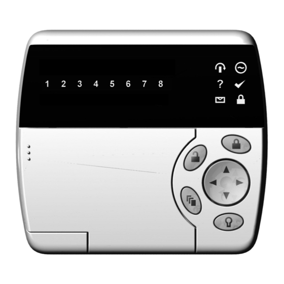
Page 13: Indicator Lights
The place values are shown in the table below: ZONE LED VALUE Zone 1 Zone 2 Zone 3 Zone 4 Zone 5 Zone 6 Zone 7 Zone 8 Binary Number Display Example 2 + 1 CYB-KLED CyberSuite Installation Manual... -
Page 14: Device Configuration
ALL 3 Digits MUST be entered when programming an address. This means that for addresses below 100, you must enter [0] then the 2 digits of the address. For addresses below 10, you must enter [0] , [0] followed by the address digit. CYB-KLED CyberSuite Installation Manual... -
Page 15: Device Options ([Menu] , [2])
Exiting Device Configuration Mode Once Device configuration is complete, press the [CLEAR] key to restart the keypad. If you do not press any key for 45 seconds while in Device Configuration mode, the keypad will automatically restart. CYB-KLED CyberSuite Installation Manual... -
Page 16: Local Installer Login
Disarm the CyberSuite system before attempting to login with the installer code. It is recommended that all installer modifications are completed and downloaded using the Protege System Management Suite (PRT- SMGT). Ensure a module update command is executed when modifications are being made. CYB-KLED CyberSuite Installation Manual... -
Page 17: Timing (Menu 1)
Where TIM 1 ~ 3 are the timer value digits, entered using the 0 to 9 number keys. Programming the exit delay timer to 0 will result in no exit delay, the system will immediately arm the CyberSuite System. CYB-KLED CyberSuite Installation Manual... -
Page 18: Alarm/Siren (Menu 1, 3)
To program the timer value, press [MENU] , [1] , [3] , [TIM 1], [TIM 2] , [TIM 3] , [ENTER] Where TIM 1 ~ 3 are the timer value digits, entered using the 0 to 9 number keys. CYB-KLED CyberSuite Installation Manual... -
Page 19: Reader Pre-Alarm Timer (Menu 1, 4)
Where TIM 1 ~ 3 are the timer value digits, entered using the 0 to 9 number keys. The minimum Left Open Time is 5 seconds, any number lower than 5 seconds entered will be automatically increased to 5 seconds to ensure correct reader operation. CYB-KLED CyberSuite Installation Manual... -
Page 20: Options (Menu 2)
Disabled Option 1 sets the zone configuration. Option 3 - Beep On Trouble Condition Enabled the beeper will emit 4 beeps every 5 minutes if a trouble condition is present, to silence the trouble beep, view the trouble condition. CYB-KLED CyberSuite Installation Manual... - Page 21 Enabled the PGM Output will follow the operation programmed by options 6 and 7, but the output will be opposite to the behaviour described in those functions. Disabled the PGM Output will follow the programmed output behaviour of options 6 and 7. CYB-KLED CyberSuite Installation Manual...
-
Page 22: Arming Options (Menu 2, 2)
Option 4 - Allow Fast Force Arming Enabled the system can be FAST FORCE armed by pressing and holding the [FORCE] key. Disabled FAST FORCE arming is disabled. Option 5, 6, 7 and 8 - Reserved CYB-KLED CyberSuite Installation Manual... -
Page 23: Reporting Options (Menu 2, 3)
Option 3 - Report Zone Bypass Enabled the system will report when the CyberSuite system is armed with zones that have been bypassed. Disabled no message will be sent when the user arms the system with zone(s) bypassed. CYB-KLED CyberSuite Installation Manual... - Page 24 Disabled no message will be sent when the extended functions are triggered. Option 8 - Reserved It is recommended not to enable/disable or modify the settings of reserved options. CYB-KLED CyberSuite Installation Manual...
-
Page 25: Panic Options (Menu 2, 4)
Option 3 - 7+9 Fire Alarm Enabled the system will generate a local fire alarm on the CyberSuite keypad and also alert the central station and on site monitoring. Disabled the 7+9 keys will not cause any alarm. CYB-KLED CyberSuite Installation Manual... - Page 26 Disabled user code 8 will operate as a standard user. Option 5, 6, 7 and 8 - Reserved Reserved. Reserved. Do not modify the reserved options configuration. CYB-KLED CyberSuite Installation Manual...
-
Page 27: Zones (Menu 3)
Zone is disabled, does not function in the system. Delay Zone will have an entry delay when a user enters. Follow Zone will not cause an alarm if the entry delay has started otherwise the zone will be an instant zone. CYB-KLED CyberSuite Installation Manual... -
Page 28: Zone Options
Option 2 - Stay Zone Enabled the zone is set as a stay zone. When the system is armed in stay mode this zone will not generate an alarm. Disabled the zone is not a stay zone. CYB-KLED CyberSuite Installation Manual... - Page 29 Disabled the zone is not able to be force armed. Option 4, 5, 6, 7 and 8 - Reserved Reserved. Reserved. It is recommended not to enable/disable or modify the settings of reserved options. CYB-KLED CyberSuite Installation Manual...
-
Page 30: Contact
Integrated Control Technology welcomes all feedback. Please go to our website or use the information below. Integrated Control Technology P.O. Box 302-340 Unit C North Harbour Post Centre 6 Ascension Place Auckland Mairangi Bay New Zealand Auckland New Zealand Phone: +64-9-476-7124 Fax: +64-9-476-7128 www.integratedcontroltechnology.com CYB-KLED CyberSuite Installation Manual... - Page 32 Unit C, 6 Ascension Place, Mairangi Bay, P.O. Box 302-340 North Harbour, Auckland, New Zealand. Phone: +64 (9) 476 7124 Fax: +64 (9) 476 7128 www.integratedcontroltechnology.com...
Need help?
Do you have a question about the CYB-KLED and is the answer not in the manual?
Questions and answers
Need someone to check my alarm. It beeps every hour