Advertisement
Quick Links
SERVICE MANUAL
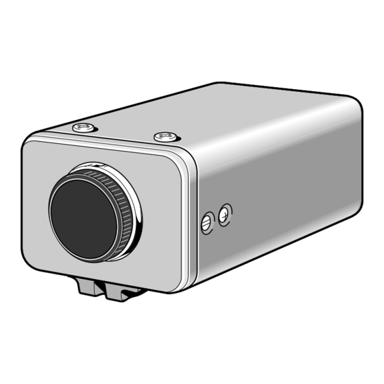
COLOUR CCD camera
SPECIFICATIONS
Scanning system : PAL standard (625 TV lines, 25 frames/sec.)
Interlace : 2:1 interlace
Image device : 1/3-inch solid-state image device CCD
Picture elements : 795 (Horizontal) x 596 (Vertical)
Effective picture elements : 752 (Horizontal) x 582 (Vertical)
Synchronizing system : Internal sync, Line lock manually switchable
Resolution : 520 TV lines horizontally, 400 TV lines vertically
Video output level : 1.0 Vp-p/75 Ω, BNC, composite
Video S/N ratio : More than 48 dB (More than 50 dB for AGC OFF)
Minimum required illumination : GAIN HI: Approx. 0.5 lx (F 1.2 lens)
(incandescent lighting)
GAIN NOR: Approx 1.0 lx (F1.2 lens)
Backlight compensation : OFF/Multi-spot metering (2 modes)/Center-weighted metering
Iris function : Manual EI/AI switching
Electronic iris range : 1.0 lx to 50,000 lx (F 1.2 lens, GAIN NOR)
Electronic shutter : 8 speeds, selectable by switches
(1/50, 1/120, 1/250, 1/500, 1/1000, 1/2000, 1/4000, 1/10000 s)
Flange-back : 12.5 mm ± 0.5 mm
White balance : ATW/Manual switching
Gain control : Normal/High switching
Aperture : Sharp/Normal switching
Lens mount : CS mount
Environmental conditions : Temperature: -10 °C – + 50 °C (14°F – 122°F)
Humidity: less than 90 % RH (no condensation)
Power supply : 220 – 230 V AC, 50Hz
Power consumption : Approx. 3.6 W (with auto-iris lens)
Weight : Approx. 600 g (without lens)
Approx. 640 g (without lens) (U.K. model only)
The components designated by a symbol ( ! ) in this schematic diagram designates components whose value are of
special significance to product safety. Should any component designated by a symbol need to be replaced, use only the
part designated in the Parts List. Do not deviate from the resistance, wattage, and voltage ratings shown.
NOTE : 1. Parts order must contain model number, part number, and description.
2. Substitute parts may be supplied as the service parts.
3. N. S. P. : Not available as service parts.
Design and specification are subject to change without notice.
L5BD5/XE, UK
PRODUCT SAFETY NOTICE
FILE NO.
VCC-6580P
(Product Code : 117 142 00)
(Europe)
(PAL General)
VCC-6580P
(Product Code : 117 142 01)
(U.K.)
CONTENTS
1. DISASSEMBLY ....................................2
2. BOARD LOCATION ............................. 4
3. ADJUSTMENT ..................................... 5
4. PARTS LIST .........................................8
CIRCUIT DIAGRAMS &
PRINTED WIRING BOARDS ................. C1
REFERENCE No. SM5310614
Advertisement

Related Manuals for Sanyo VCC-6580P


Summary of Contents for Sanyo VCC-6580P
-
Page 1: Service Manual
FILE NO. SERVICE MANUAL VCC-6580P COLOUR CCD camera (Product Code : 117 142 00) (Europe) SPECIFICATIONS (PAL General) Scanning system : PAL standard (625 TV lines, 25 frames/sec.) Interlace : 2:1 interlace VCC-6580P Image device : 1/3-inch solid-state image device CCD... - Page 2 1. DISASSEMBLY 1-1. REMOVAL OF COVER AND CA-4 BOARD 1. Screw 2 x 4 2. Cover side 3. Dec indicator 4. Screw 3 x 10 5. Two screws 3 x 6 6. Screw 3 x 6 7. Cover mounting 8. Mounting 9.
- Page 3 1-2. REMOVAL OF CA-2 BOARD, CA-3 BOARD AND CA-1 BOARD 21. CA-2 board 22. Connector 23. Four screws 2 x 5 24. CA-3 board 25. Chassis 26. Two screws 2 x 7 27. CA-1 board 28. Connector 29. Housing crystal 30.
-
Page 4: Board Location
2. BOARD LOCATION S3001 S3002 VR302 VR301 VR303 VIDEO CT232 CA-3 board (Side A) TP232 TP221 TP251 CA-2 board CT221 CA-1 board VR271 (Side A) CA-4 board CA-2 board (Side B) CA-3 board – 4 –... - Page 5 3. ADJUSTMENT 3-1. ADJUSTMENT CONDITION 3-3-1. Computer screen during adjustment 1. Use the 5,100K viewer for the subject. VHJ-0173 2. Set the trigger signal of oscilloscope to VIDEO OUT, and apply H sync unless specified. SYNC 3. Set each of the S3002 (CA-3) switches to the all OFF posi- tion.
- Page 6 3-5. White Balance Adjustment Adjustment location: VR302, VR303 (CA-3) Measuring location: VIDEO OUT Measuring equipment: Oscilloscope, Vectorscope Subject: Color bar chart Adjusting method: 1. Use the “↓” button to be A. IRIS in the adjustment window. 2. Auto iris adjustment will be started automatically. 45 µsec 3.
- Page 7 3-8. Iris Level Adjustment 3-12. Line Phase Adjustment Adjustment location: VR301 (CA-3), S3002-7,8 (CA-3) Adjustment location: VR271 (CA-2), S3002-10 (CA-3) Measuring location: VIDEO OUT Measuring location: VIDEO OUT, TP251 (CA-2) Measuring equipment: Oscilloscope Measuring equipment: Oscilloscope Subject: Gray scale chart Adjusting method: Adjusting method: 1.
- Page 8 9001 636 009 7841 LENS CAP 9110 613 204 9733 INSTRUCTION MANUAL 7001 613 204 2703 CARTON CASE INNER,EXCEPT VCC-6580P (U.K) 7001 613 204 9269 CARTON CASE INNER,VCC-6580P (U.K) ONLY 7002 613 173 5941 CUSHION SHEET 7003 613 172 3382...
- Page 9 NJ610 CA-2 NJ610 5005 NJ520 CA-3 NJ625 CA-1 6008 6007 IC101 5025 6012 8000 6011 NJ625 NJ640 NJ620 6020(N.S.P.) 6005 NJ600 NJ540 6003 5008 NJ630 NJ620 NJ600 6015 NJ600 5009 6010 NJ510 6001 NJ510 NJ600 5001 5020 NJ500 8001 NJ670 8002 8003 6000(N.S.P.)
- Page 10 ELECTRICAL PARTS Note: 1. Materials of Capacitors and Resistors are abbreviated as follows ; Resistors Capacitors MT-FILM Metallized Film Resistor MT-POLYEST Metallized Polyester Capacitor MT-GLAZE Metallized Glaze Resistor MT-COMPO Metallized Composite Capacitor OXIDE-MT Oxide Metallized Film Resistor TA-SOLID Tantalum Solid Capacitor AL-SOLID Aluminum Solid Capacitor NP-ELECT...
- Page 11 LOCATION PARTS NO. DESCRIPTION LOCATION PARTS NO. DESCRIPTION C2703 403 155 1807 CERAMIC 0.01U K 25V (CAPACITORS) C2101 403 164 0204 CERAMIC 0.1U Z 25V C2704 403 325 6304 CERAMIC 0.22U K 10V C2705 403 164 0204 CERAMIC 0.1U Z 25V C2102 403 164 0204 CERAMIC...
- Page 12 LOCATION PARTS NO. DESCRIPTION LOCATION PARTS NO. DESCRIPTION R2502 401 105 7909 MT-GLAZE 0.000 ZA 1/16W R3022 401 105 3406 MT-GLAZE 27K JA 1/16W R2506 401 105 7909 MT-GLAZE 0.000 ZA 1/16W R3023 401 105 7909 MT-GLAZE 0.000 ZA 1/16W R2513 401 105 7909 MT-GLAZE 0.000 ZA 1/16W...
- Page 13 LOCATION PARTS NO. DESCRIPTION LOCATION PARTS NO. DESCRIPTION D4203 407 174 5006 DIODE D1FS4 R4214 401 167 1105 MT-FILM 24K DU 1/16W R4215 401 105 7909 MT-GLAZE 0.000 ZA 1/16W D4204 407 078 2705 DIODE 1SS244 D4206 407 218 7706 ZENER DIODE UDZS20B-TE17 R4216 401 105 0504...