
Related Manuals for Go Power GP-PWM-30


Summary of Contents for Go Power GP-PWM-30
- Page 1 Solar Controller GP-PWM-30 Owner’s Manual © 2012 Carmanah Technologies Corporation September 2012...
- Page 2 Solar Controller GP-PWM-30 ______________________________________________________________________ © 2012 Carmanah Technologies Corporation September 2012...
-
Page 3: Table Of Contents
Installation Instructions Operating Instructions Frequently Asked Questions (FAQs) Troubleshooting Problems Problems with the Display Problems with Voltage Problems with Current Limited Warranty Repair and Return Information 10.0 Glossary 11.0 Installation Template 12.0 Wiring Diagram © 2012 Carmanah Technologies Corporation September 2012... -
Page 4: Installation Overview
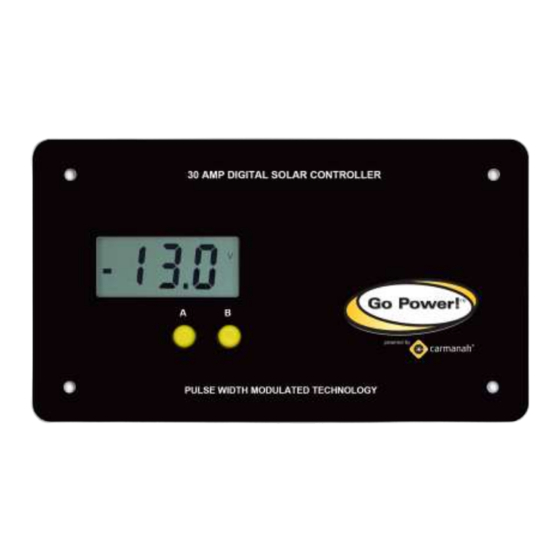
Controller prevents overcharging by limiting the current flowing into the batteries from your solar array. The GP-PWM-30 is a 12 volt flush mounted photovoltaic (PV) charge controller rated for a continuous solar current input of 30 amps. The GP-... -
Page 5: Specifications
The total rated Maximum Power Current (Imp) of the PV input should not exceed 30 Amps. The GP-PWM-30 will limit PV current above 30 Amps. Although the GP-PWM-30 will accept PV current greater than 30 Amps for a short duration, damage may occur if the GP-PWM-30 operates continuously with greater than 30 Amps of PV input. -
Page 6: Warnings
(Voc) of the PV array and voltage ratings is not to exceed 28V. If your solar system exceeds these ratings, contact your dealer for a suitable controller alternative. © 2012 Carmanah Technologies Corporation September 2012... -
Page 7: Tools And Materials Needed
Solar Power Kit installation, please refer to the Installation Guide provided with the Kit. 4.0 Choosing a Location The GP-PWM-30 is designed to be mounted flush against a wall, out of the way but easily visible. The GP-PWM-30 should be: ... -
Page 8: Installation Instructions
Installation Guide provided. Otherwise, follow manufacturer’s instructions for solar module mounting and wiring. 3. Select wire type and gauge. If this GP-PWM-30 was purchased as part of a Go Power! Solar Power Kit, appropriate wire type, gauge, and length is provided. Please continue to Section 6, “Operating Instructions.”... - Page 9 IMPORTANT: You must set the battery type on the GP-PWM-30 before you begin to use the controller. If the battery type is not selected, the GP-PWM-30 will only flash 3 dashes (---) on the screen and will not operate correctly. See section 6.0 for instructions on setting battery type.
-
Page 10: Operating Instructions
______________________________________________________________________ 6.0 Operating Instructions Power Up When the GP-PWM-30 is connected to the battery, the GP-PWM-30 will go into Power Up mode. Icons Displayed: Three horizontal dashes Setting the Battery Type / Charging Profile Set the Battery Type / Charging Profile by holding down the B Button for 5 seconds. - Page 11 A Button. Depending on the battery voltage when the GP-PWM-30 Power Up occurs, the GP-PWM-30 may do a Boost Charge or quickly go into Float Charge. The Charging Profile selected will commence the following day after a Power Up.
- Page 12 The terms FLOODED, AGM and GEL are generic battery designations. Choose the charging profile that works best with your battery manufacturer’s recommendations. Auto Equalize: The GP-PWM-30 has an automatic equalize feature that will charge and recondition your batteries once a month at a higher voltage to ensure that any excess sulfation is removed.
- Page 13 Icons Displayed: Battery, Volt Symbol (V) Push the B Button to show the PV charging current. The GP-PWM-30 will begin to limit the current as the battery reaches a full charge. Icons Displayed: Sun, Battery, Current Symbol (A) NOTE: Non-volatile memory: Any settings made on the GP-PWM-30 will be saved even when the power has been disconnected from the controller.
- Page 14 Solar Controller GP-PWM-30 ______________________________________________________________________ Errors Over Voltage If the GP-PWM-30 experiences a battery over voltage (15.5V), the controller will stop operating and the display will begin to flash. The controller will resume operating when the error is cleared. Icons Displayed: Battery, Volt Symbol, Lightning Bolt...
-
Page 15: Frequently Asked Questions (Faqs)
Ensure they are in a well ventilated space. My voltmeter shows a different reading than the GP-PWM-30 display The meter value on the GP-PWM-30 display is an approximate reading intended for indication purposes only. There is an approximate 0.1 volt inherent error present that may be accentuated when compared with readings from another voltmeter. -
Page 16: Troubleshooting Problems
(1) & (2) Check all connections from the controller to the battery including checking for correct wire polarity. Check that all connections are clean, tight, and secure. Ensure the battery voltage is above 6 volts. © 2012 Carmanah Technologies Corporation September 2012... -
Page 17: Problems With Voltage
(2) Check all connections from the controller to the array including checking for correct wire polarity. Check that all connections are clean, tight, and secure. Continue with the solutions below for additional help on low current readings. © 2012 Carmanah Technologies Corporation September 2012... - Page 18 (4) If the open circuit voltage of a non-connected 12 volt module is lower than the manufacturer’s specifications, the module may be faulty. Check for blown diodes in the solar module junction box, which may be shorting the power output of module. © 2012 Carmanah Technologies Corporation September 2012...
-
Page 19: Limited Warranty
GP-PWM-30 ______________________________________________________________________ Limited Warranty 1. Carmanah warrants the GP-PWM-30 for a period of five (5) years from the date of shipment from its factory. This warranty is valid against defects in materials and workmanship for the five (5) year warranty period. It is not valid against defects resulting from, but not limited to: ... -
Page 20: Glossary
Sealed Batteries: Electrolyte will not spill out and gassing is kept to a minimum. A sealed battery is maintenance free and may be installed in several orientations. GEL and AGM are two common types of sealed batteries. © 2012 Carmanah Technologies Corporation September 2012... -
Page 21: Installation Template
Need proper ventilation due to gassing and may need to be topped up with distilled water at regular intervals. 11.0 Installation Template (see next page) Please see supplement page (attached) © 2012 Carmanah Technologies Corporation September 2012... - Page 22 Solar Controller GP-PWM-30 ______________________________________________________________________ © 2012 Carmanah Technologies Corporation September 2012...
-
Page 23: Wiring Diagram
Solar Controller GP-PWM-30 ______________________________________________________________________ 12.0 Wiring Diagram © 2012 Carmanah Technologies Corporation September 2012... - Page 24 © 2012 GO POWER!™ By Carmanah Technologies MOBI_MAN_GP-PWM-30_vB www. electric.com...
Need help?
Do you have a question about the GP-PWM-30 and is the answer not in the manual?
Questions and answers