
Related Manuals for Go Power GP-PWM-30-UL


Summary of Contents for Go Power GP-PWM-30-UL
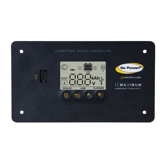
- Page 1 GP-PWM-30-UL _________________________________________________________________________________ User Manual © 2018 GoPower!
-
Page 2: Table Of Contents
GP-PWM-30-UL _________________________________________________________________________________ Contents Installation Overview Introduction System Voltage and Current Battery Type Low Voltage Disconnect Function (USB Port) Regulatory Information Specifications IMPORTANT SAFETY INSTRUCTIONS Tools and Materials Needed Choosing a Location Installation Instructions Wiring Diagram Charging Only One Battery Charging Two Batteries... - Page 3 GP-PWM-30-UL _________________________________________________________________________________ 10.0 USB Charging 11.0 Frequently Asked Questions (FAQs) 12.0 Troubleshooting Problems 12.1 Problems with the Display 12.2 Problems with Voltage 12.3 Problems with Current 13.0 Limited Warranty 13.1 Repair and Return Information 14.0 Installation Template © 2018 GoPower!
-
Page 4: Installation Overview
1.2 System Voltage and Current The GP-PWM-30-UL is intended for use at 12 VDC system voltage and is rated for a maximum continuous DC input current of 37.5A and input voltage of 35VDC. -
Page 5: Low Voltage Disconnect Function (Usb Port)
GP-PWM-30-UL _________________________________________________________________________________ 1.4 Low Voltage Disconnect Function (USB Port) To prevent the battery against over-discharge this function automatically switches off the USB output port when Battery 1 voltage is lower than 11.0 VDC. As soon as Battery 1 reaches a voltage of 12.8 VDC the USB output port is switched on again. - Page 6 GP-PWM-30-UL _________________________________________________________________________________ Operating Consumption 15mA • RoHS Compliant, (Display backlight on) environmentally safe • Accepts up to 495 Operating Consumption watts of solar at 12 (Display backlight off) volts Battery Types Supported Vented and Sealed (GEL, AGM etc.) • Maximum Power...
-
Page 7: Important Safety Instructions
_________________________________________________________________________________ 2.0 IMPORTANT SAFETY INSTRUCTIONS SAVE THESE INSTRUCTIONS THIS MANUAL CONTAINS IMPORTANT INSTRUCTIONS FOR MODEL GP-PWM-30-UL THAT SHOULD BE FOLLOWED DURING INSTALLATION AND MAINTENANCE OF THE GP-PWM-30-UL. Electricity can be very dangerous. Installation Disconnect all should be performed only by a licensed power sources electrician or qualified personnel. - Page 8 IMPORTANTES INSTRUCTIONS DE SECURITE CONSERVEZ CES INSTRUCTIONS CE MANUAL CONTIENT DES INSTRUCTIONS IMPORTANTES POUR LE MODÈLE GP-PWM-30-UL QUI DOIVENT ÊTRE SUIVIES PENDANT L’INSTALLATION ET L’ENTRETIEN DU GP-PWM-30-UL. L’électricité peut être très dangereuse. Débranchez L’installation ne doit être effectuée que par un toutes les électricien agréé...
-
Page 9: Tools And Materials Needed
Solar Power Kit installation, please refer to the Installation Guide provided with the Kit. 4.0 Choosing a Location The GP-PWM-30-UL is designed to be mounted flush against a wall, out of the way but easily visible. The GP-PWM-30-UL should be: •... -
Page 10: Installation Instructions
GP-PWM-30-UL _________________________________________________________________________________ fridge vent on the roof or by using the Go Power! Cable Entry Plate (sold separately) that allows installers to run wires through any part of the roof. PV connections should connect directly to the controller. Positive and negative battery connections must connect directly from the controller to the batteries. - Page 11 3. Select wire type and gauge. If this GP-PWM-30-UL was purchased as part of a Go Power! Solar Power Kit, appropriate wire type, gauge and length is provided. Please continue to Section 6, “Operating Instructions.”...
- Page 12 Wiring the GP-PWM-30-UL. Wire the GP-PWM-30-UL according to the wiring schematic in Section 6. Run wires from the solar array and the batteries to the location of the GP-PWM-30-UL. Keep the solar array covered with an opaque material until all wiring is completed.
-
Page 13: Wiring Diagram
690 du Code National Électrique pour l’emplacement de l’installation. Wiring Diagram The GP-PWM-30-UL Maximum 37.5A rating is based on a 30 amp total maximum short circuit current rating (Isc) from the solar modules nameplate ratings. The National Electric Code specifies the PV equipment/system rating to be 125% of the maximum Isc from the PV module ratings (1.25 times 30 = 37.5A). -
Page 14: Charging Two Batteries
équipement. 6.2 Charging Two Batteries Use the following wiring diagram if you are using the GP-PWM-30-UL to charge two separate battery banks. Connect battery bank 1 to the battery 1 terminals and battery bank 2 to the battery 2 terminals on the back of the solar controller. -
Page 15: Operating Instructions
Backlight blinks Depending on the battery voltage when the GP-PWM-30-UL Power Up occurs, the controller may do a Boost Charge or quickly go into Float Charge. The Charging Profile selected will commence the following day after a Power Up (refer to the Charging Profile Chart on page 17 for more details). - Page 16 A Button for 3 seconds. Non-volatile memory: Any settings made on the GP-PWM-30-UL will be saved even when the power has been disconnected from the controller. Refer to the Battery Charge Profile Chart below for details on each profile.
-
Page 17: Battery Charging Profile Chart
The terms SEALED/GEL, AGM and FLOODED are generic battery designations. Choose the charging profile that works best with your battery manufacturer’s recommendations. Auto Equalize: The GP-PWM-30-UL has an automatic equalize feature that will charge and recondition your batteries once a month at a higher voltage to ensure that any excess sulfation is removed. -
Page 18: Viewing The Controller Display Information
Max Power Boost and the BOOST icon cannot be turned off by pressing the Max BOOST button. 7.5 Viewing the Controller Display Information The GP-PWM-30-UL has GP-PWM-30-UL Solar Controller two modes to watch the display information, manual and auto scroll. - Page 19 GP-PWM-30-UL _________________________________________________________________________________ Push the B Button to show the PV charging current for GP-PWM-30-UL Solar Controller battery 1. The GP-PWM- 30-UL will begin to limit the current as Battery 1 reaches a full charge. The current that is not used for Battery 1, is used to charge Battery 2.
-
Page 20: Errors
GP-PWM-30-UL _________________________________________________________________________________ Icons Displayed: Arrow, Ampere Symbol, Battery SOC, Symbol 2 GP-PWM-30-UL Solar Controller The battery state of charge is shown as a percentage. Icons Displayed: Battery SOC, Percent Symbol (%), Symbol 2 Mode 2: Automatically Change Display Information You can select the auto mode by holding down the A Button for 3 seconds. - Page 21 Icons Displayed: Battery SOC Symbol, LOW, Symbol 1 or 2 Battery 1 Reverse Polarity If the GP-PWM-30-UL senses reverse polarity on battery 1, the controller will stop operating, beep continuously and display POL. The controller will resume operating when the error is cleared.
-
Page 22: Display Symbols
GP-PWM-30-UL _________________________________________________________________________________ 8.0 Display Symbols Symbol Indicator For: Battery 1 Day Time: PV Charge Current Night Time Battery Voltage Battery State of Charge SEALED Sealed/Gel FLOODED Flooded Battery 2 Day Time: PV Charge Current Night Time Battery Voltage Battery State of Charge... - Page 23 GP-PWM-30-UL _________________________________________________________________________________ Other Symbols USB charger on (When USB charger is off, no symbol will show) Inverter on (Can only be used when and inverter is hardwired. See Section 9.0. When inverter is off, no symbol shows) Max Power Boost activated, Boost...
-
Page 24: Inverter Control (On/Off)
GP-PWM-30-UL _________________________________________________________________________________ Inverter Control (on/off) The following Go Power!® inverters can be turned on/off through the GP-PWM-30-UL when a modular 6p4c RJ11 type connector is used (included with an optional Go Power!® inverter remote) GP-ISW700-12 GP-ISW1500-12 GP-ISW1000-12 GP-ISW2000-12 GP-SW1000-12 GP-SW2000-12... -
Page 25: Usb Charging
GP-PWM-30-UL _________________________________________________________________________________ 10.0 USB Charging The GP-PWM-30-UL offers a standard USB connector for delivering 5.0 VDC to small mobile appliances such as cell phones, tablets, small music players. This charging port is capable of supplying up to 800 mA of current. -
Page 26: Frequently Asked Questions (Faqs)
There may be a slight difference between the battery voltage displayed on the GP-PWM-30-UL display and the battery voltage measured at the battery terminals. When troubleshooting using a voltmeter, check both the battery voltage at the GP-PWM-30-UL controller terminals and battery voltage at the battery terminals. - Page 27 GP-PWM-30-UL _________________________________________________________________________________ What causes a warning signal and when are the warnings triggered? Connection Warning Notes “POL” on LCD Battery 1 reverse and constant polarity audible alarm Battery 1 must be Battery 2 Battery 2 status connected with display doesn’t...
-
Page 28: Troubleshooting Problems
GP-PWM-30-UL _________________________________________________________________________________ 12.0 Troubleshooting Problems How to Read this Section Troubleshooting Problems is split into three sub-sections, grouped by symptoms involving key components. Components considered irrelevant in a diagnosis are denoted ‘Not Applicable’ (N/A). A multimeter or voltmeter may be required for some procedures listed. -
Page 29: Problems With Voltage
GP-PWM-30-UL _________________________________________________________________________________ Possible Causes: Panel is covered by something; PV panel is too dirty to supply a high enough voltage to charge the battery; PV panel is not connected. Remedy: Check the panel and to ensure it is not obscured. Clean the panel if it is dirty. - Page 30 GP-PWM-30-UL _________________________________________________________________________________ How to tell: 1. The State of Charge (SOC) screen is close to 100% and the Sun and Battery icon are present with an arrow between. 2. With the solar array in sunlight, check the voltage at the controller solar array terminals with a voltmeter.
- Page 31 GP-PWM-30-UL _________________________________________________________________________________ (2) Check that the modules and batteries are configured correctly. Check all wiring connections. (3) Modules look dirty, overhead object is shading modules or it is an overcast day in which a shadow cannot be cast. Avoid any shading no matter how small. An object as small as a broomstick held across the solar module may cause the power output to be reduced.
-
Page 32: Limited Warranty
GP-PWM-30-UL _________________________________________________________________________________ 13.0 Limited Warranty 1. Go Power! warrants the GP-PWM-30-UL for a period of five (5) years from the date of shipment from its factory. This warranty is valid against defects in materials and workmanship for the five (5) year warranty period. It is not valid against defects resulting from, but not limited to: •... - Page 33 GP-PWM-30-UL _________________________________________________________________________________ © 2018 GoPower!
- Page 34 GP-PWM-30-UL _________________________________________________________________________________ © 2018 GO POWER!® By Valterra Products, LLC MOBI_MAN_GP-PWM-30-UL_vG electric.com © 2018 GoPower!
Need help?
Do you have a question about the GP-PWM-30-UL and is the answer not in the manual?
Questions and answers