Advertisement
Quick Links
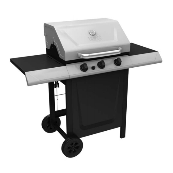
T440 Barbecue
Assembly Manual
85-3004-2 (G45118) Propane
85-3005-0 (G45119) Natural Gas
1 YEAR LIMITED WARRANTY
READ AND SAVE MANUAL FOR FUTURE REFERENCE.
If pre-assembled, leave this manual with unit for
consumer's future reference.
For product inquiries, parts, warranty and
troubleshooting support, please call 1-877-707-5463.
Manual Revision #: 30082011 PD
Advertisement

Related Manuals for Master Chef T440


Summary of Contents for Master Chef T440
- Page 1 T440 Barbecue Assembly Manual 85-3004-2 (G45118) Propane 85-3005-0 (G45119) Natural Gas 1 YEAR LIMITED WARRANTY READ AND SAVE MANUAL FOR FUTURE REFERENCE. If pre-assembled, leave this manual with unit for consumer’s future reference. For product inquiries, parts, warranty and troubleshooting support, please call 1-877-707-5463.
-
Page 2: Hardware Pack
HARDWARE PACK TOOLS NEEDED FOR ASSEMBLY KEY # DESCRIPTION PART NUMBER QUANTITY 1/4” x 13mm Screw 20120-13013-036 • #2 Phillips screwdriver (long and short) Wing Screw G306-0025-9084 1/4”-20UNC Nut 31220-13000-036 • ¼” Slotted screwdriver (long and short) #8X3/8” Self Tapping Screw 22500-42010-136 •... - Page 3 PARTS LIST (PROPANE) FOR 85-3004-2 (G45118) EXPLODED DIAGRAM (PROPANE) FOR 85-3004-2 (G45118) KEY # QUANTITY DESCRIPTION PART NO. Top Lid assembly G451-3000-01 Thermometer and Bezel G451-0008-01 Top Lid Handle G413-0001-01 Lid Bumbers- Back G303-0038-01 Lid Bumbers- Front G430-00B8-01 Screws for Lid G430-0024-01 Burner Box Assembly G451-0200-01...
- Page 4 PARTS LIST (NATURAL GAS) FOR 85-3005-0 (G45119) EXPLODED DIAGRAM (NATURAL GAS) FOR 85-3005-0 (G45119) KEY # QUANTITY DESCRIPTION PART NO. Top lid assembly G451-3000-01 Thermometer G451-0008-01 Top lid handle G413-0001-01 Lid bumbers- back G303-0038-01 Lid bumbers- front G430-00B8-01 Screws for lid G430-0024-01 Burner box assembly G451-0200-01...
-
Page 5: Assembly Instructions
ASSEMBLY INSTRUCTIONS ASSEMBLY INSTRUCTIONS PROPANE MODEL ONLY Note: Turn Cart assembly upside down. a. Place wheel (DG) and wheel spacer (#7) onto Note: You will need two people for this step. wheel axle (DH). “Cone” side of wheel should be against cart side panel, as shown in figure B. Assemble the tank exclusion (EE) to the left and right cart side panels (DA, DB), as shown. - Page 6 ASSEMBLY INSTRUCTIONS ASSEMBLY INSTRUCTIONS RIGHT SIDE SHELF ASSEMBLY Note: Stand cart assembly upright. TWO PEOPLE required for this step. Ensure that a. Insert the right side shelf assembly hooks into the regulator hose (Propane models only) is the grooves located on the right side of the hanging outside of cart.
- Page 7 ASSEMBLY INSTRUCTIONS ASSEMBLY INSTRUCTIONS LEFT SIDE SHELF ASSEMBLY PROPANE MODEL ONLY a. Insert the left side shelf assembly hooks (EC Insert and fasten the tank retainer clip (EF) into and ED) into the grooves located on the left the tank retainer bracket, located at the top, side of the burner box assembly (BA).
- Page 8 ASSEMBLY INSTRUCTIONS ASSEMBLY INSTRUCTIONS Place the cooking grates (BF) into the burner box. Hang the grease cup hook (CG) from the bottom of the burner box (BA), and place grease cup (CH) into position. PROPANE MODEL SHOWN CAUTION Failure to assemble grease cup hook and grease cup will cause hot grease to drip from the bottom of the BBQ burner box, with the risk of Back view...
- Page 9 ASSEMBLY INSTRUCTIONS NATURAL GAS MODELS ONLY Attach the natural gas hose (CC) to the manifold (CB), as shown. ATTENTION: In order to complete installation of your natural gas BBQ a 1/2” or 3/8” adapter may be required to connect your BBQ’s natural gas hose to your home gas supply.
Need help?
Do you have a question about the T440 and is the answer not in the manual?
Questions and answers